
Executive Viewpoint: Building the foundation for a low-emission LNG facility
Electric LNG (i.e., eLNG) has emerged as a powerful decarbonization pathway for LNG project stakeholders. However, the development of these facilities often presents unique technical challenges not encountered with traditional gas turbine-driven designs.
One critical facet that needs to be addressed is integrating the onsite power generation unit (PGU) and the liquefaction island. Traditionally, the parties involved with the design and engineering of these facilities have operated in silos, often with different mindsets and objectives. In addition to potentially limiting opportunities for total plant decarbonization, this type of project approach increases the likelihood of encountering technical problems that can lead to costly rework. It can also present issues if and when plant modifications need to be made or operating conditions change (e.g., capacity or power demand increases, renewable energy sources are integrated, etc.)
To ensure optimum uptime and create the lowest possible plant emissions profile, a more holistic design approach is required where there is close collaboration between the power/utility and liquefaction design teams starting in the early phases of the project timeline. At Siemens Energy, we refer to this concept as “integrated electrical and LNG plant design.”1
eLNG vs. mechanically driven plants. In a traditional gas turbine-driven LNG facility, the driver selection determines how much power is available for compressors and dictates LNG train capacity. While the liquefaction plant owner-operator provides a desired nominal design capacity for the facility based on factors such as available feed, LNG demand, export regulations, financial decisions, etc., gas turbines come in discrete sizes. As a result, the LNG capacity is usually designed to fully utilize the site-rated gas turbine power for maximum profit.
When designing an eLNG facility, capacity limitations may appear superfluous in that the operator is no longer constrained by the gas turbine driver when setting the capacity. However, because electricity generation is primarily done with gas turbines, determining the “sweet spot” of the PGU in terms of efficiency is essential for maximizing efficiency and optimizing CAPEX. This sweet spot can be determined by utilizing cogeneration and a close match between the site-rated power and the LNG production (FIG. 1).
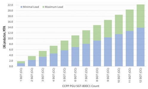 |
| FIG. 1. LNG production rates of various combined-cycle power plants using SGT-800C1 in combination with cogeneration. As the power generation facility increases in capacity, so does the range of LNG production for a given design. |
Moreover, developing the liquefication and power facilities separately results in a highly inefficient project workflow. In most cases, the process design team starts by creating the electrical demand for the main refrigeration trains and then feeding it to the PGU team. Often, the PGU team must feed information back to the process team, which then initiates additional rework.
Adopting an integrated PGU-LNG train facility development approach makes it possible to avoid this iterative design process and identify issues early on during FEED that can impact efficiency, availability, CAPEX and overall plant emissions.
Production and use of process heat. With mechanically driven trains, refrigerant compressor driver power and process heat come from the mechanical drive gas turbines. In an eLNG facility, however, the paradigm is shifted. The thermal heating required for the LNG process units comes from the PGU through waste heat extraction or steam. This requires evaluating the needed heat and power during the LNG facility’s normal, steady-state operation and during startup, shutdown and upset scenarios.
One example of this is during startup—a topic typically ignored in the early design stages of the LNG train in relation to the PGU. At an eLNG plant with a PGU operating in island mode, a delicate balance exists between the amount of steam available for process heating relative to the electrical load demand. Logically, the LNG train starts up from the upstream gas processing unit and cascades down to the liquefaction and storage facilities. This standard startup sequence results in a higher ratio of process heating load to electrical power demand during the first steps of a startup, compared to the ratio of design to steady-state. Exceeding the design ratio indicates an imbalance to the system that would require supplemental process heat to be supplied by another source.
Adding a furnace to provide the heat necessary during startup is a potential solution. However, this will result in higher emissions and add a piece of equipment typically not used in normal operations. A temporary furnace rental is another solution, but it may not be feasible, depending on the LNG train capacity. In some instances, it may also be possible to address the heat imbalance by proposing an alternate startup sequence.
The best option will ultimately be dictated by the unique requirements of the plant and operator, and it can be determined only by evaluating the power plant and liquefaction island together, holistically.
Electrical grid stability. Equally important to ensuring a reliable supply of process heat is the stability of the plant’s electrical grid.
PGUs in LNG facilities are typically classified as operating in island mode. This mode is coined as such because the PGUs are not connected to an external power grid—e.g., a local municipality. If the electrical grid is unstable, then the LNG train would be forced to trip and shut down, resulting in a loss of revenue.
In such installations, maintaining a balance between power generation and electrical load consumed is crucial. Active and reactive power imbalance can lead to frequency and voltage deviations, and without sufficient reserve, frequency and voltage regulation may present serious problems. Therefore, the electrical system must ensure voltage and frequency stability in all scenarios at all times. A comprehensive electrical system evaluation is essential for ensuring reliability at any continuous process facility; however, it is particularly so when renewables enter the energy mix.
Several LNG projects across the world are now evaluating the use of renewable power sources to reduce emissions. More specifically, this is being considered in combination with conventional natural gas generation to create a hybrid system.
Integration of renewables adds benefits, but it also complicates the stabilization of the plant electrical grid. For example, a photovoltaic (PV) plant can provide support during over-frequency cases. The challenge, then, is making the energy system flexible enough to cope with this transition.
The renewable power output from solar or wind is highly dependent on renewable source availability. A possible solution to balance this intermittence is to use energy storage. Power production and demand can be balanced by storing electricity in times with adequate wind and sun, and then feeding this power into the grid on windless and cloudy days.
Storage technologies are differentiated according to the amount of energy that can be stored and the length of time it can be stored. Battery storage systems (BSS) are examples of conventional methods that store energy for short-term periods (i.e., minutes or hours).
Pumped-storage power plants are employed, or hydrogen can be used as an energy vector when it comes to mass energy storage for more extended periods. BSS also help distributed generation operators to integrate and better utilize power generation from renewable sources. They compensate for the volatility of renewable sources by either storing energy to be injected at a different time when demand or the price of energy is higher, or by quickly charging and discharging power to respond to surges and dips in renewable power availability, thereby ensuring a smooth output to the load. As a result, BSS contribute to optimizing energy costs, and their programmable and controllable fast response times improve matching supply and demand. The decision to incorporate energy storage is also crucial for sparing philosophies and redundancy to ensure high availability.
LNG operators typically design PGUs with a target availability of 99%+ because it is considered a utility that should always be available to the LNG train. To achieve this, the PGU is designed to a minimum N + 1 configuration, where N is the minimum number of gas turbines required for operation at 100%. In other words, PGUs are designed with a spare gas turbine that can either be running or offline, depending on the operating philosophy. A running spare will result in the gas turbines running at lower loads, away from the optimal load, for the highest efficiency. On the other hand, an offline gas turbine will require supplemental power by power augmentation or a battery when the gas turbine is started up. Otherwise, a load shedding procedure must be implemented to keep the LNG train operational.
Fuel system. In mechanically driven LNG plants, natural gas used during startup and refrigerants that must be de-inventoried from equipment are sent to the facility’s flare system for proper disposal. The contents are burned, and thermal energy is emitted into the atmosphere. However, these streams can instead be recovered and routed to the fuel gas system for conditioning. In such cases, the hydrocarbons will be utilized as a component of the blended fuel gas for the PGU.
Processing the streams through the fuel gas system is essential because of the heating value variation control inherently provided by the residence time designed in the fuel gas mixing drum. If the heating value rate of change varies outside of a prescribed range, then the gas turbine generators could be tripped. Consequently, the heating value of the recovered hydrocarbons must be known; so, too, will its impact on the overall fuel blend heating value to avoid exceeding the rate of change allowed for normal operation.
Moreover, a solution where recovery of these streams is envisioned requires additional kit and plot space not accounted for in a traditional LNG facility design. Thus, an integrated approach that includes an evaluation provides a more robust design and limits potential rework in the future.
Takeaway. Despite its growing role in the global energy mix, the carbon footprint of the LNG industry is being put under the microscope by activists, investors, lenders and regulatory bodies. The total emissions profile of an LNG plant is now a key consideration for stakeholders. It can significantly impact whether or not a project reaches a final investment decision (FID).
Electrification is an important pathway to the decarbonization of LNG facilities, providing immediate advantages in terms of higher-efficiency operations and lower emissions, while allowing for current or future implementation of renewables and green fuels (FIG. 2).
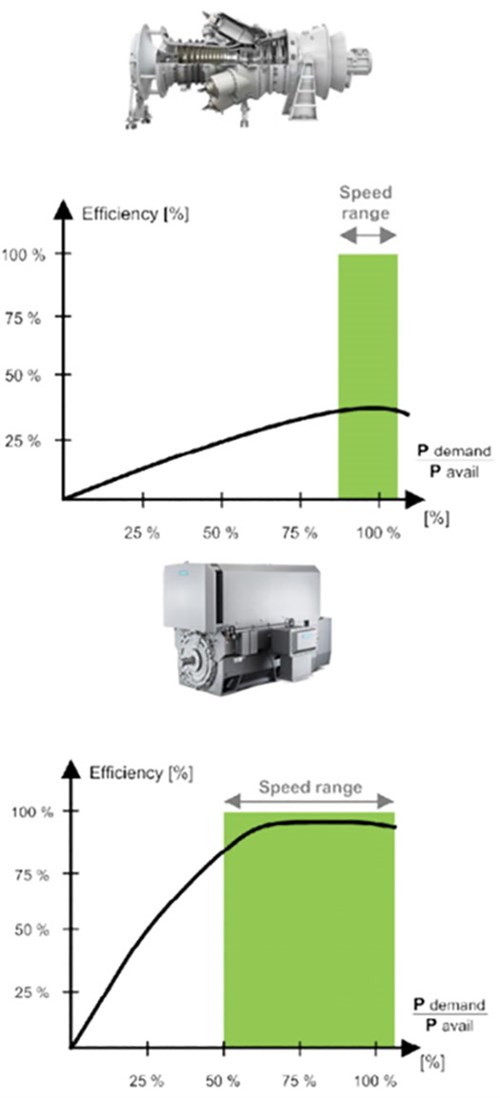 |
| FIG. 2. Refrigerant compressor driver efficiency: Gas turbine (top) vs. electric motor (bottom). |
In the same way that refrigeration compressor mechanical drive gas turbines have been viewed as key to optimizing all aspects of LNG plant performance, the focus with eLNG is now shifting to the source of power generation, requiring a new, integrated approach to its design and specification. In light of this development, a strong case can be made to move toward a more holistic design approach where the required process and electrical systems are developed in parallel to enable total plant optimization. GP
LITERATURE CITED
- Adams, J., J. Ergina and R. Filho, “Integrated electrical and LNG plant design,” Presented at Gastech, September 21–24, 2021, Dubai, UAE.
 |
JENNIFER ADAMS is the Head of Decarbonization Engineering for Siemens Energy’s Industrial Applications business. In this role, she leads the project development activities for new markets focusing on decarbonization and sustainable energy. Prior to joining Siemens Energy, Ms. Adams worked with a large EPC firm in the hydrocarbon industry, including 15 yr in a leadership role where she executed major LNG projects. She holds a BS degree in engineering from Texas A&M University.


Comments