
Enhance efficiency and decarbonize gas operations with the organic Rankine cycle
P. DANESI and S. MILANESI, Exergy Intl., Milan, Italy
According to International Energy Agency (IEA) reports, today’s oil and gas operations are responsible for ~15% of total energy-related emissions globally, the equivalent of 5.1 B metric t of greenhouse gas (GHG) emissions. The sector is far behind to remain on track with its energy transition target requiring it to halve its emissions by the end of this decade.
For the oil and gas industry, several technologies and measures are available to cut the emissions intensity of its operations and reach the target of a 60% reduction by 2030, as sought in the IEA’s “Net zero emissions by 2050 scenario (NZE).” Improving the energy efficiency of oil and gas operations is one of the key measures. Even small-scale efficiency improvements throughout the oil and gas value chain can translate into a large impact on global carbon reduction. In Accenture’s “Decarbonizing Energy: From A to Zero” study, the company’s analysts estimate that ~700 MM metric t of carbon dioxide (CO2) direct emissions from oil and gas activities could be avoided by deploying energy efficiency and circular solutions.
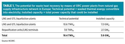
Leveraging untapped waste heat potential in gas infrastructure network. In the gas sector, recovering the waste heat available from processing operations and converting it into carbon-free electricity represents a good opportunity with effective outcomes for emissions reduction and energy savings. Gas turbines, employed for natural gas compression and in regasification terminals, reject roughly 50% of the energy contained in the fuel into the atmosphere through their exhaust systems. Considering this factor only, it is clear that the potential of the waste heat available and untapped in the gas sector is sizable. In its “Thermal energy harvesting” study (TABLE 1), the Knowledge Center of Organic Rankine Cycle (KCORC) estimates a technical potential of 18.4 TWhel of electricity for a 3.6-GWel installable capacity that can be produced from the waste heat available in the European gas supply infrastructure, at the level of liquefied natural gas (LNG) and gas-to-liquids (GTL) liquefaction plants and in LNG regasification terminals.
In the 2015 “Waste heat to power market assessment” prepared for the U.S. Department of Energy (DOE), the analysis identified a total estimated waste heat-to-power (WHP) technical potential of 1,102 MWe from 1,300 sites in the U.S. natural gas pipeline transmission network.
Due to the difficulty of collecting updated information about the amount and temperature level of the thermal energy discarded to the atmosphere globally, and considering that data are often not collected or are unavailable to the public, the real amount of recoverable thermal energy estimated by the available studies is expected to be remarkably higher.
ORC technology for waste heat recovery (WHR). When it comes to recovering waste heat and converting it into electricity, the ORC is the ideal technology, especially for low- to medium-high temperatures applications (90°C–400°C) or for small power size.
An ORC is similar to the traditional steam Rankine cycle widely employed in power stations—it differs due to the use of organic substances rather than water as working fluid for the cycle. The organic working fluid has a lower boiling point and higher vapor pressure than water and is, therefore, able to use low-medium temperature heat sources to produce electricity more efficiently than the steam cycle. The organic fluid (mainly hydrocarbons or refrigerants) is chosen to best fit the heat source, thus obtaining higher efficiencies.
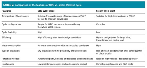
As shown in TABLE 2, operational flexibility with high efficiency at a variety of load cases, the possibility of avoiding the use of water and the lower maintenance costs of ORC technology are some of the advantages over the steam Rankine cycle. TABLE 2 shows some of the factors that have made ORC the growing and preferred choice for waste heat recovery installations in the industrial sector over the last decades.
In 2010, the authors’ company, one of the leading suppliers of ORC systems worldwide, introduced an innovative radial outflow turbine (ROT) like the one shown in FIG. 1.
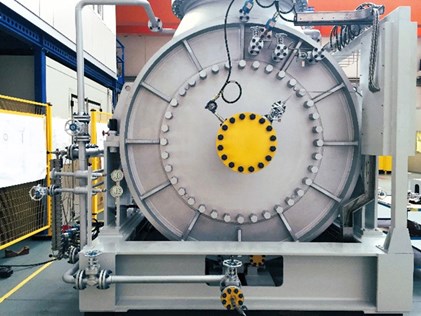
FIG. 1. An ROT for an oil and gas application.
The use of the ROT in ORC systems offers several benefits when compared with systems using axial or radial inflow turbines. Due to its radial configuration and technical features, ROT technology leads to:
- Higher efficiency due to:
-
- Natural accommodation of working fluid expansion through the radial outflow arrangement of turbine stages
- Up to nine stages on a single-disk turbine, reducing the size and length of the turbine compared to axial turbines
- Less tip leakage and disk friction losses
- Minimum 3D effect thanks to the low blade height and low blade height variation
- Less limitation on cycle pressure, leading to a superior flexibility and extending the application range
- Multiple pressure admissions possible on a single-disk turbine, allowing a more competitive and efficient exploitation of resources
- Simplified construction technology, more compact and easier to transport and install
- No gearbox needed thanks to the low rotational speed of the turbine that allows a direct coupling with the generator
- Decreased vibrations, which leads to longer plant life
- Easy and low-cost maintenance: the patented mechanical group of the turbine containing the bearings, oil lubrication system and seals can be easily removed without draining the organic fluid away from the cycle—this also dramatically reduces plant downtime during maintenance, which can be carried out in ~1 d.
These advantages lead to competitive, flexible and efficient ORC systems that allow a high level of customization to adapt to specific project requirements.
WHR opportunities in the gas sector. For the gas sector, there are several options to recover waste heat by using ORC systems and turbines.
One of the more traditional and proven applications of an ORC WHR system is in gas turbines driving compressors in use in pipelines (FIG. 2).
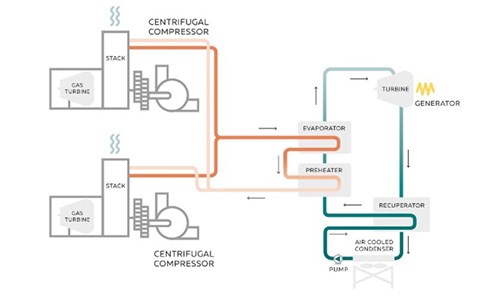
FIG. 2. ORC cycle scheme for WHR from a gas compressor station.
In a gas compressor station, this application can be an extremely efficient solution to produce power in all operating conditions. Advantages include:
- There is no impact on gas turbine flexibility, but offers very quick ORC response to transient conditions.
- Heat recovery is possible from multiple units operating in parallel—one ORC unit applied to multiple gas turbines driving the station can increase the power output by up to 40%, optimizing cost and efficiency.
- It is possible to use ORC output either for power generation or as mechanical power backup.
Other advantages to consider are related to operation and environmental footprint. Gas compressor stations are often located in isolated or remote areas with limited access to water supplies and are frequently operated remotely without a permanent staff onsite. These limitations have no impact on the feasibility of ORC installations. ORC systems can operate without water and are fully automated systems that can be controlled remotely.
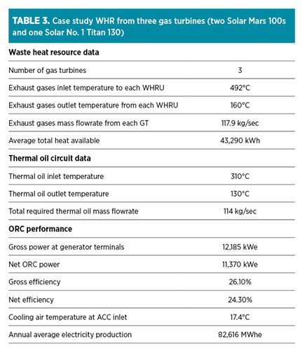
In TABLE 3, a case study is presented for recovering waste heat available from three gas turbines in a gas compressor station with an average total heat available of 43,290 kWth at around 500°C. Transferring the heat to the ORC by means of a heat transfer oil circuit, it is possible to generate 12 MWe power for an annual average electricity production of 82,616 MWhe.
Thermal energy is not the only type of recovery possible in the gas sector. An interesting application to enhance the efficiency of gas operation through other types of energy recovery is offered in gas pipeline pressure let-down (PLD) stations (FIG. 3). In PLD stations located at various steps along the pipeline network, gas pressure is reduced to allow safe distribution to local grids to serve industrial, commercial and residential end users. Pressure reduction is normally achieved in PLD stations by using throttling valves. In this process, a high amount of potential energy, available as high-pressure difference, is completely lost in the throttling process.
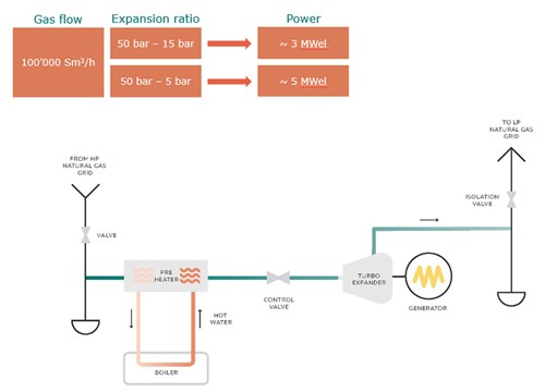
FIG. 3. A WHR with a gas expander in PLD stations.
This unused energy can be efficiently recovered to produce zero-emissions electricity through a gas expander. In this system, a heat exchanger for gas preheating is positioned upstream of the expander while the PLD station throttled valves are replaced with the expander (turbine). A generator is coupled with the expander to produce electricity while achieving, at the system outlet, the desired pressure and temperature for natural gas distribution.
The authors’ company’s research and development (R&D) department has recently developed a natural gas expander system that integrates into existing PLD gas stations to increase the efficiency and sustainability of the gas distribution system. This solution has been conceived to allow a very high level of customization to maximize efficiency. Depending on process conditions and requirements, it is possible to tailor the system design choosing among three different configurations using an ROT, or radial-axial or fully axial expander, thus achieving the highest performance. The system can increase the efficiency of the PLD by up to 80%.
Using an example of an application on a PLD station considering a 100,000-m3/hr gas flow and an expansion ratio from 50 bar to 5 bar, approximately 5 MWe of electricity could be produced using a configuration with the authors’ company’s high-speed axial turbine to recover the waste available. With an expansion ratio from 50 bar to 15 bar, some 3 MWe could be generated.
This solution achieves an efficiency of 80%, while the average efficiency of a standard turbine employed in these systems is around 70%.
Cold energy recovery in an LNG regasification terminal. An interesting application of the ORC technology in the LNG sector is to recover the cold energy potential available from regasification processes.
During the production phase, natural gas is liquefied by cooling at cryogenic temperature (roughly –160°C at 1 atmospheric pressure) to reduce its volume and ease transportation and storage. Natural gas refrigeration is an energy-intensive process: energy consumption for liquefaction averages 500 kWh of electricity consumed per ton (t) of LNG produced, which corresponds to roughly 3.6% of the natural gas lower heating value (LHV).
Before being delivered via the transportation and distribution network, LNG must be pressurized (usually at 80 barg–120 barg) and returned to its gaseous state. The regasification occurs at LNG import terminals in vaporizers. Conventional vaporizers are submerged combustion (SCV), open-rack (ORV) and intermediate-fluid (IFV) types. Seawater is the heat source for the latter two, while in an SCV, a fraction of natural gas is combusted and the flue gases heat a pool of water that later provides heat to the LNG. In these types of vaporization processes, a considerable amount of the energy used in the liquefaction phase (~28%) is wasted to the environment. Additionally, these processes are energy intensive—they require the consumption of electrical energy (for LNG pumps and water pumps in an ORV) and/or regasified gas (in the case of an SCV).
ORC technology offers an efficient and market-available solution to harness the cold energy potential from LNG and make the process more efficient and sustainable. A cold energy plant (CEP) based on ORC technology regasifies LNG and converts the heat absorbed from seawater into electricity by recovering the valuable energy content of LNG.
The authors’ company’s R&D efforts have recently brought to patent an innovative CEP achieving high efficiency thanks to the use of the proprietary ROT combined with a multilevel condensation cycle. Conventional ORC systems are characterized by a single level of condensation and the use of propane, R13, R22 or R23 as working fluid. This single-condensation plant configuration is characterized by a condensation curve that does not match the LNG vaporization and strongly limits the turbine expansion and, therefore, the ORC plant power production.
To overcome this ORC performance limitation, the authors’ company developed and patented a multi-level condensation ORC CEP with the goal to maximize the LNG heat sink along the vaporization curve and increase the cycle efficiency, maximizing the electrical power production at the requested regasification rate. The patent allows up to four levels of condensation, with the use of a single feed pump in the ORC circuit and the company’s ROT. Advantages of the multi-level condensation with a single feed pump include:
- Increased cycle efficiency, higher specific power production and improved cold energy recovery factor than single level.
- Single pump configuration, enabled by a throttling valve at the high-pressure condenser outlet. A single, low-suction pressure pump reduces the complexity of the ORC plant and lowers plant capital expenditure (CAPEX), decreasing the critical equipment exposed to cryogenic temperatures, lowering stops for maintenance and improving higher plant annual availability.
- Suitable for using propane as a working fluid, which is generally considered one of the best performing among hydrocarbons and has high market availability at low cost—in fact, propane has already been successfully employed in conventional IFVs and many cryogenic applications. Other advantages of propane include low global warming potential (GWP < 10) and moderate vacuum in low-pressure condensers (> 0.1 bara).
Additional advantages are specifically connected to the use of the ROT:
- The isentropic efficiency of the ROT is high both in on- and off-design conditions due to the optimization of the velocity triangles, its multiple reaction and action stages, and the natural radial increase of the passage area, which allows the expansion to a high volumetric flow ratio.
- The ROT configuration naturally allows spillages between stages in a single-disc turbine, therefore enabling the multi-level condensation pressure level ORC in a single machine. Additionally, there is no need for multiple turbines at different pressure levels.
- The ROT shaft length, unlike axial turbines, does not need to be increased to make room for the spillages point clearance—this avoids several rotor dynamic problems for an overhung configuration.
- The low rotational speed of the ROT makes it possible for the direct drive to operate without an additional gearbox.
FIG. 4 shows the patented multiple condensation levels of an ORC plant in two-condensation pressure levels configuration, while FIG. 5 shows a 3D model. An LNG regasification plant in Rayong, Thailand with a WHR ORC installation is shown in FIG. 6.
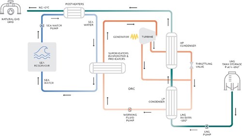
FIG. 4. The authors’ company’s multi-level condensation ORC CEP in a two-pressure level configuration.
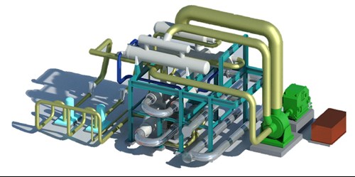
FIG. 5. 3D model of the authors’ company’s multi-level condensation ORC CEP in a two-pressure level configuration.
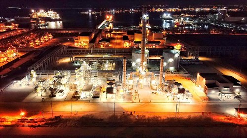
FIG. 6. LNG regasification plant with WHR ORC installation in Rayong, Thailand. Source: Exergy International.
Although the patent allows up to four levels of condensation, the company’s internal analysis has indicated that two levels of condensation is the optimum compromise among efficiency, plant complexity and overall CAPEX.
In the case study presented in TABLE 4 from a 1-MMtpy LNG regasification plant, it is possible to produce 4.3 MWe with the company’s CEP, a net power production of > 18% over conventional ORC. An estimated reduction of 10,000 tpy of CO2 emissions was an additional benefit.
Takeaway. Currently, cold energy utilization accounts for less than 1% of its total potential—an estimated 2.5 GWe could be produced, which could be further boosted by climate change policies. In the gas value chain, waste heat potential is enormous, and its recovery and reuse offer a unique opportunity for energy efficiency improvements and carbon footprint reduction.
ABOUT THE AUTHORS
Paolo Danesi earned a chemical engineering degree from La Sapienza University. He has extensive experience in business development and sales in international markets in the energy, heavy industry and engineering fields. Prior to Exergy, he worked for Alfa Laval, Sofinter and Fata Hunter. Danesi has been with Exergy since 2023. His primary role is sales/business development with offices/teams in Italy, Turkey and Malaysia.
Sara Milanesi is a communication professional with 20 yr of experience working for various public relations, consultancy agencies and energy companies. She is skilled in corporate communications and in business-to-business marketing strategies to support sales growth. She has been with Exergy since 2015 and is responsible for communications and marketing.


Comments