
The impact of imposed high-temperature piping loads on the chronic failures of steam turbine-driven compressor units in gas compression plants
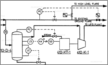
This article examines liquefied petroleum gas (LPG) gas compressors that employ steam turbines as drivers (FIG. 1) which consistently faced chronic issues during operating conditions—compressor trips due to malfunctions were observed on the turbine side. Bearing overload conditions due to deviations in shaft centerline, significant piping movements in the steam header of the turbine during startup, and severe misalignment at operating conditions were some notable observations. This article details the steam system piping layout from a piping stress and flexibility standpoint, the imposed loadings on the turbine nozzles, and the susceptibility to water hammering and condensate carryover. An investigation of the analytical methods employed for this trouble-shooting is presented.
 |
|
FIG. 1. Steam turbine-driven LPG compressor. |
Given the restrictive space around the inlet and exhaust piping layout in the equipment area, feasible technical recommendations were proposed and implemented. These recommendations were considered the most optimum to reduce the current nozzle loads, which included redesigning restraints and springs supports at select locations as well as modifications related to steam traps and associated condensate removal from piping.
Hydrogen sulfide (H2S) and light hydrocarbons are stripped in the stabilizer as overheads flow to the rich gas collection headers that feed the gas compressors at natural gas liquids (NGL) plants. These LPG gas compressors employ steam turbines as drivers with 600# steam piping on the inlet system and 150# steam piping at the exhaust system.
One compressor tripped repeatedly due to a high radial bearing temperature at the turbine outboard side. Even after the subject turbine was overhauled and installed back into service, it failed again similarly within 45 d in operation. Some of the immediate observations noted included:
- A bearing overload condition due to a deviation in shaft centerline, exceeding normal bearing clearance
- Significant piping movements in the turbine steam header during startup
- A severe misalignment of piping at support locations during operating conditions
- Improper piping support functionality during operations.
However, these observations must be translated to objectives of assessment that can identify the structured analytical methods to enable a systematic investigation.
Problem statement. To further systematically investigate the causes listed above—the bearing overload condition, deviation of the shaft’s centerline position and severe misalignment of the turbine at operating conditions, as well as the improper piping support configuration—the following three-fold objective was established:
- A detailed piping flexibility and stress evaluation of the inlet and exhaust piping of the steam turbines was required to verify if the sustained and expansion stresses were within the acceptable limits of ASME B31.3 for the existing piping layout.1
- A detailed turbine nozzle loads evaluation was required due to the steam piping connecting the inlet and exhaust nozzles for each of the turbines to verify if the existing nozzle loads were within the acceptable limits specified by NEMA SM-23 in the current operating condition.
- Some critical deficiencies were observed on the inlet and exhaust piping of the turbines with respect to efficient condensate removal. A detailed mechanical assessment was completed to verify if the existing piping configurations had the following deficiencies:2
- The presence of condensate carryover into the steam turbines
- The presence of condensate-induced water hammer (CIWH).
Piping stress and flexibility analysis. A piping stress and flexibility analysis of the existing piping configurations (based on as-built conditions) was completed in accordance with ASME B31.3 requirements, using the beam elements with 6° of freedom with commercially available softwarea. FIG. 2 illustrates the 12-in. 600# steam inlet lines connected to each of the two turbines.
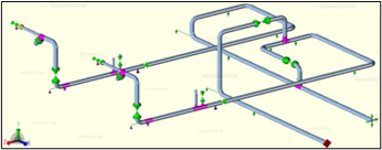 |
| FIG. 2. Piping stress-flexibility model inlet. |
FIG. 3. illustrates the 20-in. exhaust lines similarly connected to the steam turbines. Typically, the steam inlet and outlet lines have been included in separate pipe stress models.
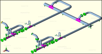 |
| FIG. 3. Piping stress flexibility model exhaust. |
Turbine expansion displacement (α-thermal coefficient of expansion) values, as shown in TABLE 1, were applied as the boundary conditions for the piping stress and flexibility analysis.
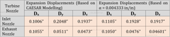 |
| TABLE 1. Turbine thermal displacements |
A static analysis was completed to evaluate sustained, operating and expansion stress categories, which were found to be well within ASME B31.3 allowable limits.
Turbine nozzle loading evaluation. The turbine expansion displacement values were based on the turbine nozzle model illustrated in FIG. 4, which was developed for nozzles modeling.
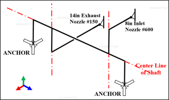 |
| FIG. 4. Steam turbine model. |
Typically, suction and discharge lines are included in separate pipe stress models. The loadings on each steam turbine nozzle were computed based on the piping stress and flexibility analysis results completed in the previous section. The turbine equipment was then evaluated to determine whether these loads are acceptable to the governing Steam Turbines NEMA (National Electrical Manufacturer's Association) Standard SM23. Two types of force/moment allowable values are computed during an NEMA run:
- Individual nozzle allowable values
- Cumulative equipment allowable values.
For cumulative equipment allowable values, the combined results of the forces and moments of the inlet, extraction and exhaust connections were resolved at the centerline of the exhaust connection—this was then evaluated as per NEMA SM23 limits. The nozzle loads evaluation was completed for the two scenarios here:
- The existing piping configurations (as-built field conditions)
- The proposed piping support modifications (new springs and modified supports condition).
The results shown in TABLE 2 confirm that both the inlet and exhaust nozzles for each of the turbines failed the required limit loads (as specified by NEMA SM-23) in the current operating condition by large values. This was clearly an unacceptable condition for the continued safe and reliable operations of the steam turbines. Although the piping stress and flexibility check had passed the code stress check, the existing piping layout imposed excessive external loading on the turbine nozzles. To mitigate this unacceptable condition, it was proposed to modify the piping support by installing additional spring supports and modify the spring constant for other specific spring supports. A static analysis was completed to re-evaluate the sustained category (SUS) and expansion category (EXP) of piping stresses based on proposed piping support modifications (new springs and modified supports condition), which were found to be well within ASME B31.3 allowable limits. Therefore, the code stress check passed for all lines.
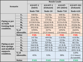 |
| TABLE 2: Turbine thermal displacements |
Steam piping layout evaluation. A field assessment was completed for the 600# and 150# steam piping system piping layouts connecting the pipe way steam header to the turbine inlet and exhaust nozzles. The following observations were based on isometrics of the existing design and field visits:
- From a piping flexibility design perspective, the 600# steam piping around the turbines presented several design deficiencies, both from a piping layout and support application.
- It was observed that the immediate pipe sections before the turbines’ isolation valves are extremely long (> 20 m), transferring all thermal growth to the first anchor support, making it a stress riser and aggravating the nozzle loads situation.
- The existing spring supports were, in fact, inactive either by corrosion or by inadequate degrees-of-freedom at the upstream/downstream sections.
- Signs of water hammering and condensate carryover were noticed on 600# steam piping supports. The supports were originally designed with vertical stoppers to limit the horizontal movement of the pipe. However, these stoppers were found to be severely damaged and bent at an angle from their original vertical design.
- The damage to these stoppers prevents them from performing their function of limiting the horizontal movement of the pipe, thus transferring all thermal loads to the turbines’ inlet nozzles.
- Several low points on the header lacked proper condensate removal measures (drip legs, steam traps, etc.), creating condensate pockets at these low points. Condensate accumulated at these low points can be sent to the turbines, especially after extended periods of outage.
- Several piping layout design deficiency issues may have increased the potential for steam condensate carryover. This was noticeable due to the lack of proper condensate drainage via drip legs and steam straps.
- Existing steam traps were insufficient, not working properly, and/or impractical to maintain and operate, as the valve hand wheels were corroded or damaged.
- The condensate carryover was aggravated at the turbine where the turbine isolation inlet “warm-up” bypass line is connected from the bottom of the drip leg to the downstream. This presents a high risk of sending condensate from the drip leg to the turbine rotor, which might provoke condensate impingement and catastrophic turbine failure.
Takeaway. The most common failure mechanisms associated with steam piping are:
- CIWH can be caused by rapid condensation of steam by sub-cooled water. This can occur in several different ways, the most common of which is by steam flowing over sub-cooled water.
- A steam-propelled water slug can occur when a steam valve is opened, causing a pressure difference across a water slug and resulting in a slug movement and associated damage.
Both of the above failure mechanisms are strictly associated with the accumulation of condensate. Therefore, the piping layouts of the 600# and 150# steam lines connecting the pipe way header to the turbine inlet and exhaust nozzles were evaluated for the presence/absence of the following design features required for the efficient removal of condensate:
- Carefully chosen steam trap locations
- The correct functionality of steam trap design for this application
- Proper supports and correct angles of the steam piping
- Drip legs configured to allow for the smooth removal of condensate
- Proper removal of air and condensate at end-of-lines. GP
NOTES
a CAESAR-II
LITERATURE CITED
- The American Society of Mechanical Engineers (ASME), “B31.3 Process Piping Standard.”
- The American Society of Mechanical Engineers (ASME), “ASME Boiler and Pressure Vessel Code, Section VIII, Div-1: Rules for construction of pressure vessels,” 2021.
ABOUT THE AUTHOR
Aslam Kittur works in the Technical Services Division of the Global Manufacturing Admin Area of the downstream segment of Saudi Aramco. He is a Mechanical Engineer with expertise in troubleshooting integrity issues related to refinery static equipment and has more than 23 yr of experience in the energy industry (upstream, offshore and downstream), specializing in performing stress analyses to understand the complex failure mechanisms of critical equipment. His focus is on establishing root causes for repetitive failures and developing solutions to ensure reliable design for any given operating conditions. Kittur earned an MS degree in solid mechanics and employs FEM-based structural and thermal simulations that are often required for a Level-III API-579 fitness-for-service evaluation. Prior to joining Saudi Aramco, he was involved in a similar capacity for 10 yr in Canadian oil sands facilities.


Comments