
Fouling in gas processing facilities: Testing, root cause analysis and mitigation—Part 2
Fouling in gas processing facilities can take on several different forms, depending on the conditions where it occurs and the contaminants involved. In some cases, deposition occurs slowly over a period of years, and monitoring and mitigation requires methods with a high degree of accuracy and trace contaminant detection. In other cases, fouling occurs rapidly and causes equipment failures in a matter of weeks—the onset of issues is often rapid, as well, requiring diligent monitoring and analysis on a frequent or continuous basis. In every case, however, it is critical to have a program in place to monitor for the precursors to fouling and determine the rate of fouling when it is occurring.
Part 1 of this article, which appeared in the November issue, explored case studies and the challenges presented by fouling in gas processing facilities. Further case studies and potential solutions are discussed here.
CASE STUDY 3—AMINE SOLVENT ACTIVATOR PRECIPITATION
A gas plant in West Texas, U.S. with observed fouling sent foulant samples to the authors’ company’s laboratory for detailed analysis. The foulant sample was obtained from the treated gas stream between the contactor and the dehydration stage. Solids were found in the treated gas piping and in the strainers, as seen in FIG. 8. The unit performance also declined in terms of higher CO2 content in the treated gas.
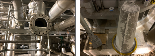 |
| FIG. 8. Foulant material in amine contactor-treated gas piping (left) and strainer (right). |
The foulant material can be seen in better detail in FIG. 9. The solids were white in color and had a very light, powdery nature (similar to baking flour). Smaller black particles were observed within the white solid matrix. The solids gave an odor of amine. Basic solubility testing was done initially to determine what type of solids the material contained. The white solids were insoluble in hexanes but readily soluble in water, turning the water phase yellow, while the small black particles within were not dissolved. It was also noted that the sample yellowed over time if exposed to atmosphere. These results indicated that the foulant material was primarily a water-soluble, metal-based salt with trace levels of small insoluble particles. Based on all these properties, one potential candidate was piperazine residues, as the plant was using high concentrations of piperazine in its (methyl diethanolamine) MDEA-based solvent.
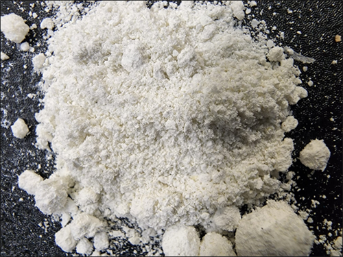 |
| FIG. 9. Foulant material, as received. |
The foulant material was analyzed using infrared spectroscopy to better understand the organic components present. FIG. 10 shows the spectrum for the foulant as well as that for piperazine, an activator used in the amine solvent upstream. Some similarities existed between the two, but several shifted signals suggested that a piperazine-based salt was, in fact, present instead.
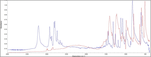 |
| FIG. 10. Infrared spectra for foulant material (red) and piperazine (blue). |
The elemental composition of the foulant was also determined. The composition of the foulant was measured at 45% carbon, 22% oxygen, 21% nitrogen, 9% hydrogen and 3% other trace elements. Given the infrared spectrum and elemental composition of the sample, the presence of a piperazine-based salt was highly likely. A possible mechanism for the formation of such salts is shown in FIG. 11. The pathway involving H2S was not possible due to low sulfur levels, and the pathway involving acetic acid was possible, but unlikely. Carbonate or bicarbonate salts were the more likely foulant product. To mitigate fouling, it was recommended to modify operations to prevent spray flow in the absorber, mitigate foaming as much as possible, and minimize the amount of activator used in the solvent formulation. A water wash at the contactor outlet to wash the treated gas was also suggested.
 |
| FIG. 11. Potential mechanisms for piperazine salt formation. |
This case demonstrated the need for advanced analytical capabilities, a system for implementing them correctly, and the knowledge required to interpret results. Conventional analytical methods often will not identify unique contaminants in gas processing applications. Given the wide range of potential contaminants, it is difficult to identify exactly what fouling precursor molecules are present, especially when it is not clear what to look for. More basic techniques, such as a solubility study, are first required to identify the type of contamination, and then it can be determined what other analyses may best characterize the sample. Even when suitable methods for analysis are used, it is still critical to interpret the data correctly in cases where results are not totally clear or exact. In this case, the authors’ company was able to identify the contaminant from IR data despite no exact match in the component library.
CASE STUDY 4—LIQUID HYDROCARBON INGRESSION AND FOULING
A midstream processing operation in Canada was experiencing issues with fouling in the structured packing of a methanol recovery tower stemming from contamination in the methanol/water feed. The methanol recovery unit is utilized to separate and recover methanol from water. Methanol is used in upstream and midstream operations for applications such as hydrate inhibition in natural gas streams. The feed to the unit was composed of several different aqueous streams that were mixed in tankage onsite before processing at the methanol recovery unit. The water stream (FIG. 12) comprised three main phases: water/methanol, free hydrocarbons and suspended solids. Contaminants in the feed caused fouling and plugging of both the tower packing and the bag-style feed filters (reducing their online life), and stabilized emulsion formation at the three-phase separators, preventing complete hydrocarbon removal.
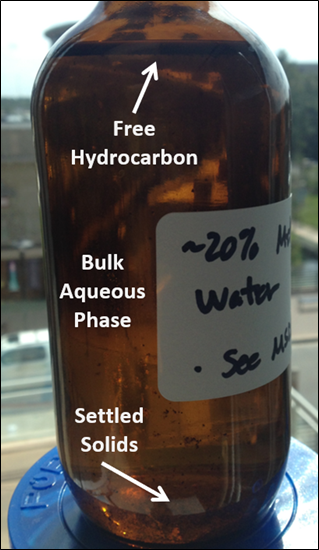 |
| FIG. 12. Methanol recovery tower feed. |
The levels of contamination in each phase of the feeds to the methanol recovery unit were quantified. It was determined that both feed sources contained approximately 1% v/v free hydrocarbon. The levels of suspended solids and dissolved contaminants were very high and also very similar among both feed sources. It was therefore determined that both sources were likely contributing to fouling. Given that the level of contamination in each phase was high, further investigation was required to determine which contaminant types were contributing to fouling issues.
Solids were analyzed and found to contain barium sulfate from upstream drilling, carbonates from scaling, corrosion products from upstream corrosion, formation solids (sand/silt/clay) and salts: these components all have the potential for deposition and fouling in the methanol recovery tower. The bag filters in place upstream of the tower were evaluated, and the internal bag elements were found to have very low surface area. New elements with pleated media and expanded surface area were recommended to reduce the flux through the media below 0.5 gpm/ft2 (filtration lifetime decreases exponentially at lower fluxes) and improve lifetime by an estimated 250%–750%.
The primary recommendation was that further investigation of the fouling potential of liquid hydrocarbons and dissolved components in the feed be conducted. It was unclear whether improved filtration alone would mitigate fouling, as hydrocarbon agglomeration or polymerization and the precipitation of salts and other contaminants were also possible.
One of the best and most accurate laboratory tests to determine fouling tendencies of a process fluid is the hot liquid process simulator (HLPS). The apparatusb used for this experiment is depicted in FIG. 13. The HLPS is a dynamic process simulation used to predict fouling in a scaled-down and accelerated way. The system consists of a reservoir charged with sample fluid that is pumped through a test section by a downstream pump. An electrically heated element forms an annulus through which the fluid flows, and the temperature of the element is precisely controlled by a thermocouple located in its interior. Process conditions are reproduced by adjusting the flowrate and pressure of the fluid and the temperature of the element. Since the tower operating temperature was approximately 200ºF, the HLPS element temperature was set to 250ºF to accelerate the rate of fouling in the laboratory test.
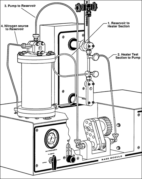 |
| FIG. 13. HLPS for fouling tendency determination. |
Three different samples were tested using the HLPS: a feed sample as received, a filtered feed sample, and a filtered sample with liquid hydrocarbons removed. The objective of the tests was to determine whether hydrocarbons or dissolved components caused fouling once suspended solids were removed. The results of each test are shown in FIG. 14: the increasing difference in temperature between the heating element and the fluid during testing indicates an increase in fouling of the heating element. FIG. 14 shows that there was almost no increase in temperature differential when the sample was filtered and the liquid hydrocarbon removed, but the temperature differential in the untreated sample increased at nearly the same rate as the filtered sample with liquid hydrocarbon still present. Two important findings were gained from the results: dissolved contaminants did not cause fouling, but liquid hydrocarbons did.
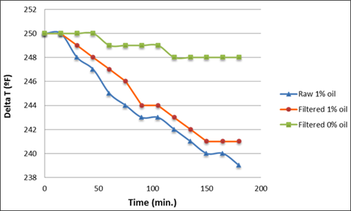 |
| FIG. 14. HLPS testing results. |
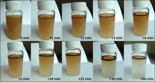
Filtration of suspended solids alone would not mitigate fouling due to the presence of liquid hydrocarbons, so actions had to be taken to remove the hydrocarbon, as well. Gravity separation testing was conducted to determine the separation time of the mixture, and at least 15 min–20 min of residence time were determined to be necessary, as depicted in FIG. 15. Hydrocarbon removal upstream was recommended, as well as installing skimming of the feed tank and implementing an emulsion breaker additive. The plant improved separations upstream of the methanol recovery tower to remove hydrocarbons more effectively, and the filtration system was also improved to extend filter lifetimes. Fouling rates decreased significantly after hydrocarbon removal improved.
 |
|
FIG. 15. Gravity separation of liquid hydrocarbons in tower feed over time. |
This case is an excellent example of applications where the root cause of the fouling issue was unexpected, and the extra effort taken to determine the root cause before implementing a solution proved to be extremely valuable. It was initially suspected that the methanol recovery tower was fouling due to high suspended solids, and the plant at first only desired to improve feed filtration. After the initial feed sample was analyzed and found to contain contaminants other than suspended solids, the plant was wise to further explore the present contamination. Fouling testing using the HLPS then confirmed that filtration alone would not reduce fouling significantly, and the plant avoided wasted costs on an ineffective solution.
CASE STUDY 5—‘SHOE POLISH’ FORMATION
Amine units in some facilities—and tail gas treating units (TGTUs) downstream of a Claus sulfur recovery unit (SRU)—are often considered a collection point for contamination due to their position in the process. In conventional gas plants and LNG facilities, the amine unit is usually at the front end of the plant and must handle contamination from the feed gas. In refineries, amine units process feed from sources all over the plant and receive contaminants that move through and are generated in those systems. Amine units in gas plants and refineries also often share solvent using a common regenerator, so contamination ingression at any one contactor can end up affecting the entire amine system.
A TGTU at a U.S. refinery was dealing with fouling in its amine system due to contaminant ingression into the circulating amine solvent. The plant observed the accumulation of a sludge-like material in the rich amine, and the rich amine filters were frequently becoming completely saturated with the material. FIG. 16 shows the difference between the lean and rich solvents and the sludge material coating the rich amine filters.
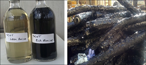 |
| FIG. 16. Lean and rich amine solvent (left), and rich amine filters after service (right). |
FIG. 17 shows a sample of the material from the rich amine filters in more detail; this sample was used for analysis of the material. A portion of the sample was mixed with hydrochloric acid, and gas evolution was observed shortly thereafter. A pH strip exposed to the gas vapors indicated that the vapors were acidic in nature. These results suggested that iron sulfide was reacting with the hydrochloric acid to form H2S gas and iron chloride. There was a delay prior to gas evolution after mixing with acid due to the presence of residual amine and liquid hydrocarbons coating the iron sulfide material.
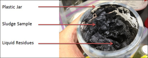 |
| FIG. 17. Foulant material used for analysis, as received. |
Another portion of the sludge material was used for solubility testing. A small amount of foulant was added to four different solvents. It was determined that the material was insoluble in naphtha or toluene and partially soluble in methanol or water. After several days, more material appeared to dissolve in water, resulting in an orange color. Another portion of the material was again mixed with water and then filtered, and it was determined that 68% w/w of the sample dissolved into the water phase. The water with dissolved material was analyzed for several components. High levels of iron, sulfate, heat stable salts, organic acids and amine were detected. The presence of heat stable salts in a TGTU was unusual and indicated either breakthrough of sulfur dioxide (SO2) from the upstream offgas treating processc or ingression of a different amine solvent from another unit.
The remaining solids after filtration were analyzed for their elemental composition using EDX analysis and organic components using IR spectroscopy. The IR spectrum for the solids (FIG. 18) suggested the presence of amine and water, aliphatic and aromatic hydrocarbons, glycols and alcohols. EDX analysis revealed the solids were made up entirely of iron (60% w/w) and sulfur (40% w/w).
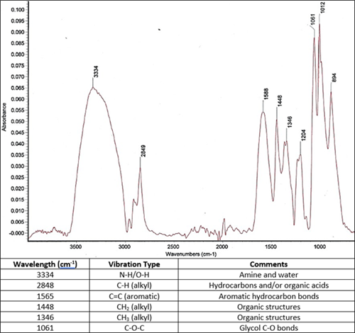 |
| FIG. 18. IR spectrum and signal matches for solids from sludge material. |
The performed tests and analysis indicated that ‘shoe polish’ material was present. Shoe polish is consistent predominantly with insoluble and crystalline iron sulfide clusters encapsulated in a matrix of water-soluble polymeric iron sulfides, heat stable salts, amine residues and minor hydrocarbon traces. This material is generated in other amine units and some TGTUs when heat stable salts are present in the solvent. Interestingly, only water and other polar-hydroxyl solvents can disrupt the amorphous association within the sludge and partially dissolve certain sections of the nearly gelatinous material. This liberates the solid iron sulfide particles and other water insoluble components. Amine solvent, in contrast, will not dissolve the material, thus its accumulation in the circulating solvent. Hydrocarbon-based solvents are incapable of similar solubilization and are a minor component in the shoe polish material. Perhaps the most important information gained was revealed by the water-soluble species present in the residue, which were similar to what is found in amine units contaminated with heat stable salts (typically associated with FCC and coker refinery units).
The fact that the TGTU contained the shoe polish contamination material, even though heat stable salts do not generally form in these systems, suggested that amine solution contaminated with heat stable salts was somehow being routed to the TGTU from the other amine units. Further performance simulation studies and analysis confirmed that the TGTU operating with MDEA amine solvent was contaminated with DEA from another amine unit. This cross-contamination was the root cause of the contaminants found in the amine solvent, leading to the formation of the shoe polish material and ultimately leading to the failure of the filtration system. The plant made the necessary changes to prevent cross-contamination from other amine units, and fouling rates then decreased notably.
This case re-emphasizes that the classification of contaminants with regards to what phase they are in can yield useful information. The case also shows that simple methods with solid background knowledge can reveal important information. Shoe polish is very commonly mistaken for hydrocarbon-based deposition, and efforts to mitigate the issue would be futile if operating under that assumption. The formation of shoe polish in a TGTU is very unlikely and so was not suspected until preliminary testing of the foulant was completed. A simple solubility study with the material to confirm the type of contaminant revealed it was mostly water-based. This was vital to understand to determine what other analyses would further characterize the sample.
Takeaways. Fouling in processing facilities can have numerous origins and several fouling mechanisms (chemical, thermal, suspended, solidification and biofouling, among others). It is important to sample the foulant material and perform detailed analyses. By determining its composition, one can retro-analyze back to the foulant precursors leading to the fouling episodes. It is important to consider the fouling precursors ingression to the process (feed, supplies in contact with the process or process-generated). Therefore, contamination control to minimize suspended solids and emulsion ingression to the process are fundamental. However, in some cases, none of these sources are the cause of fouling and attention must be turned to operations or dissolved contaminants. In any case, a defined fouling control program that includes monitoring and periodic sampling, resources and expertise in analysis, and experience and knowledge in troubleshooting is critical for proper mitigation. GP
 |
NOTES
b Alcor 300 System
c Shell Claus off gas treating process (SCOT)
 |
DAVID ENGEL is the Managing Director for Nexo Solutions and a PhD chemist with more than 20 yr of industrial experience in a variety of areas ranging from chemical synthesis to phase separation technologies. Dr. Engel is the inventor in 21 U.S. invention patents on various subjects relating to technology development for sensors, nanotechnology, coatings, pharmaceuticals, pipeline systems, chemical additives and separation technology. He has also presented a number of seminars on a variety of technical subjects throughout the Americas.
 |
SEBASTIAN ENGEL is the Laboratory Manager at Nexo Solutions and has extensive expertise in chemical consulting and laboratory analysis. He is responsible for laboratory services, including testing, quality control, research and development, sample analysis and customer support. Engel has conducted chemical analyses that have successfully discovered and characterized contaminants found in many different industrial processes. He studied chemistry at Sam Houston State University.
 |
SCOTT WILLIAMS is a Senior Process Engineer at Nexo Solutions and has industry experience in many projects in oil and gas, chemical and water treatment applications. As part of the engineering group, Williams is responsible for onsite testing, troubleshooting and process optimization at various plants and provides support for contamination control technologies and analytical projects. His recent work has been focused on feedstock contamination control, debottlenecking and asset protection. Williams holds a BS degree in chemical and biological engineering from the University of Colorado at Boulder.
 |
CODY RIDGE is a Lead Process Engineer at Nexo Solutions and is responsible for field engineering and technology development, as well as process optimization and operational support. His recent projects include feed gas conditioning systems and root cause determination for contamination. Ridge is a chemical engineer from Texas Tech University and has worked as an operator and process engineer in the Permian Basin.


Comments