
Fouling in gas processing facilities: Testing, root cause analysis and mitigation—Part 1
Fouling in gas processing facilities can take on several different forms, depending on the conditions where it occurs and the contaminants involved. In some cases, deposition occurs slowly over a period of years, and monitoring and mitigation requires methods with a high degree of accuracy and trace contaminant detection. In other cases, fouling occurs rapidly and causes equipment failures in a matter of weeks—the onset of issues is often rapid, as well, requiring diligent monitoring and analysis on a frequent or continuous basis. In every case, however, it is critical to have a program in place to monitor for the precursors to fouling and determine the rate of fouling when it is occurring.
FIG. 1 depicts and categorizes the precursors to fouling that are common in gas processing facilities. The contaminants in natural gas and processing intermediates can exist in four forms: in the gas phase, as solids, as hydrocarbons in a distinct liquid phase or the gas phase, or as dissolved components either in the liquid water, liquid hydrocarbon or gas phase. Each fouling precursor can affect the process differently regardless of what phase it is in, but methods for its detection, monitoring and sometimes mitigation are often the same or similar. For example, dissolved contaminants in water can, in many cases, be monitored through pH, total dissolved solids (TDS) and conductivity measurements, and mitigation techniques such as pH control or solid bed adsorption can be employed and are useful for several different contaminants in the aqueous phase.
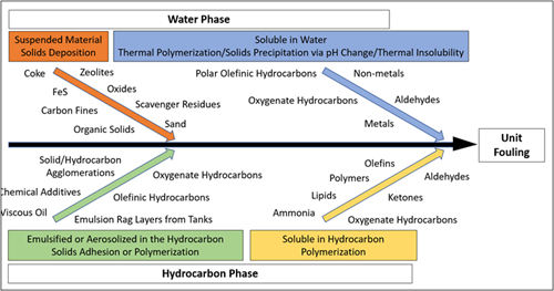 |
| FIG. 1. Precursors to unit fouling in gas processing facilities. |
Suspended solids are the most common and obvious precursor to fouling in most gas processing applications. The most common source of suspended solids in almost all processes is corrosion products. Iron sulfides, oxides and hydroxides can take on various forms and form deposits on their own or in combination with other solids or liquid hydrocarbons as an agglomerate. Formation solids from upstream production such as sand/silt/clay are also very common. In some plants, upstream additive use leads to solid byproducts, including coke/carbon/catalyst fines, scavenger residues, or organic polymers and gels. Suspended solids are ideally removed at their source via specific mitigation techniques to prevent ingression with the feed source; however, when this option is infeasible, filtration is often employed.
Dissolved contaminants in the water phase include ions and metals that can lead to salt formation and precipitation, hydrocarbons with polar functionalities such as organic acids or corrosion inhibitors and other additives, and methanol used as a hydrate inhibitor. Surfactants are also often present and promote emulsification with hydrocarbons. Dissolved aqueous contaminants are ideally removed by removing any free or emulsified water that enters with the feed to the plant using properly designed slug catchers, inlet separators and coalescers. In cases where this is infeasible or when contaminants become dissolved in process solvents, mitigation techniques such as activated carbon adsorption or ion exchange are often implemented.
Liquid hydrocarbons are often present in varying compositions in gas plant feeds in their free or emulsified/aerosolized form, and the nature of the hydrocarbon depends on its source. Condensable hydrocarbons with very low molecular weights (such as butane or pentane) condense at lower temperatures (often at night) and can cause issues downstream in some cases. Lubrication oils used at compressors upstream are also extremely common and contain additives that can lead to polymerization fouling or agglomeration with solids. Hydrocarbon solvents from additives used upstream are also sometimes present at low levels and contain a vast range of potential fouling precursors. Surfactants are also often present in these hydrocarbons and promote emulsification with water in the feed and process solvents. As with free or aerosolized water in the feed gas, removal of hydrocarbon liquids using properly designed slug catchers, inlet separators and coalescers is ideal for mitigation. In cases where this is infeasible, flash tanks, knockout drums, coalescers and other separators at downstream units must be well equipped to remove liquid hydrocarbons.
Contaminants in the gas phase can also affect fouling. Ammonia, for example, can be present as a dissolved component in the liquid water phase but also can exist in the gas phase when no free or aerosolized water is present. The same is possible for hydrocarbon-soluble components, such as organic acids or olefins, in the absence of liquid hydrocarbon. Monitoring for these precursors can sometimes be done via the same gas chromatography (GC) analysis performed for the feed gas composition; however, in certain cases, analysis and detection of gas phase components requires specialized testing. Once identified, fouling precursors in the gas phase can be removed ideally at their source; if not, a water or solvent wash of the feed gas can be implemented to extract and remove the contaminants.
CASE STUDY 1—AMMONIUM SALT DEPOSITION
A natural gas processing plant in West Texas, U.S., was experiencing a variety of issues related to solids deposition, including:
- A premature failure of the mole sieve dehydration bed where methanol and BTEX contamination was identified
- Pressure drop in the cryogenic unit where a solid and water-soluble material with a strong ammonia and sulfur odor was identified
- The presence of hydrogen sulfide (H2S) in the cryogenic unit outlet downstream of the expander during startup or flow changes.
It was suspected that contamination discovered in the demethanizer tower and at the inlet and outlet of the plant were contributing to these issues. The plant requested that these contamination samples be analyzed for their contents and to identify potential origins. The authors’ company was contacted to conduct preliminary analysis of foulant samples, perform onsite feed gas contamination testing, collect and further analyze samples, address the issues observed, and make recommendations for general contamination mitigation.
It was determined from preliminary foulant analysis that ammonia or ammonium salts were the primary contaminants present in the demethanizer, which is rare in gas processing facilities but can originate from the use of ammonium hydroxide for pH adjustment, H2S scavenging or biocides usage (among others). Ammonium carbonates/bicarbonates and sulfides/bisulfides were the specific components detected. Iron carbonates/bicarbonates and corrosion products were also detected in the reboiler foulant in addition to ammonium salts, as well as mole sieve fines or silica and salts from produced water. Ammonium salts were again detected in solids from a sample of liquids from the dehydration unit inlet coalescer. Iron carbonates, salts from produced water, pipeline additives, pigging residue products, lubrication oils and polyester residues—likely from coalescing media degradation and upstream chemicals—were also detected.
Formation of ammonium bicarbonate (NH4CO3) can be understood by the chemical reactions in the equations below. If ammonia or ammonium hydroxide is exposed to carbon dioxide (CO2) in the presence of water, the acid-base reaction with carbonic acid will take place, producing ammonium bicarbonate. This material can produce solid depositions at specific locations in a facility. The same rationale can be applied for the formation of ammonium carbonate (NH4)2CO3, ammonium bisulfide NH4HS or ammonium sulfide (NH4)2S. These were found in lower proportions compared to ammonium bicarbonate.
 |
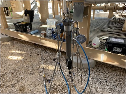
Based on the findings obtained from preliminary analysis, it was recommended to change the media material on the inlet coalescer elements, test a slipstream of feed gas and sample inlet contaminants, and determine the root cause of ammonium salts or ammonia entering the facility. To properly assess contamination levels and contamination breakthrough or carryover in a gas stream, effective removal and quantification of all liquids in the stream is necessary. This was accomplished by using the authors’ company’s GASCO small-scale testing unitsa (FIG. 2). The units use a high-pressure housing equipped with a proprietary coalescer media designed for the capture and separation of liquid contaminants and aerosols in the gas stream. The small-scale testing systema also has instrumentation to measure flow, pressure, differential pressure, liquid buildup levels and sampling ports.
 |
|
FIG. 2. The small-scale test systema setup at dehydration unit inlet. |
Three of these units were used at three different locations. Two units at the plant with observed issues were connected at the outlet of the mole sieve bed feed gas coalescer and downstream of the mole sieve bed dust filter. One unit at a neighboring plant with no observed issues and a different feed source was connected at the outlet of the mole sieve bed feed gas coalescer as a control comparison. Through the run time of the unitsa, no significant changes were detected in dP or pressure, normal variations in temperature from day to night, and no variation in flowrate except when manually adjusted. The fact that no differential pressure was observed during the test period indicated that minimal solids accumulation was taking place. No aqueous liquids were measured in the feed gas at the plant with observed issues. Only a low level of liquid hydrocarbons was measured, and that was due to condensation from a relatively rich gas composition.
To determine whether any contaminants leading to fouling were present in the gas phase, a water wash injection and recirculation was conducted at each system. Water was injected into the inlet of each small-scale test system setup where it contacted the gas and extracted contaminants, and the water was then coalesced and drained from the internal coalescing element into the sight glass, where it was collected and added back to the water injection pump suction. This process was repeated 10 times to saturate the injected water with as much soluble contamination as possible to allow for effective chemical analysis. The wash water samples produced were analyzed for ammonia and other relevant parameters, as shown in TABLE 1.
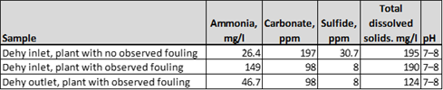 |
| TABLE 1. Wash water analysis results at plant dehydration units |
The level of ammonia was approximately six times higher at the dehydration bed inlet at the plant with fouling issues compared to the plant without observed issues. This result suggested that ammonia was contributing to fouling at the plant. The level of ammonia was lower in the dehydration bed outlet at the plant with fouling issues, suggesting that deposition or adsorption was occurring in the mole sieve beds. Also of note, the level of sulfides and carbonates was lower at the plant without fouling issues, which showed that the presence of ammonia was the driving force for potential salt precipitation.
Based on findings from onsite testing, several recommendations were made to improve and add to existing contamination control assets. An investigation was recommended to determine the source of ammonia addition from upstream producers. The plant initiated this process by contacting upstream producers that provide gas to the plant and acquiring lists of additives used along with safety data sheets. The authors’ company reviewed the additives used and determined several that were likely ammonia-based chemistries (or could generate ammonia as a byproduct). Ten feed sources were eventually identified that were most likely to be contributing significantly to ammonia ingression and fouling, and the company conducted feed gas contamination testing with a water wash injection test again at each source location. The results of analysis for ammonia in wash water samples as well as the flow contribution for each feed source are shown in TABLE 2.
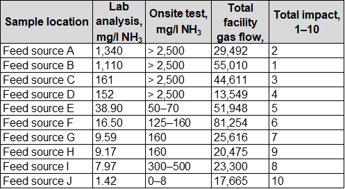 |
| TABLE 2. Water wash analysis results at feed source locations |
The level of ammonia in each feed source varied significantly—two sources in particular were measured to contribute the majority (> 80%) of ammonia contamination. Four other sources contained a significant degree of ammonia (> 1% of the total), and four additional sources contributed a negligible amount of ammonia. Based on these findings, additives used at the feed sources with high ammonia levels were investigated further. Those additives with potential ammonia or ammonia byproducts were discontinued or replaced with different chemistries.
After additives with ammonia were removed from each feed source, fouling rates at the plant decreased significantly. This case is an example where more advanced testing and analysis were required to determine the sources of gas phase contamination. If fouling is suspected, it is critical to take the extra step to test for gas phase contaminants when fouling precursors are not found in the solid or liquid phases. It is also important to gather as much data as possible about the plant feed. Communication with upstream personnel can assist considerably in determining the source of contamination and potential solutions.
CASE STUDY 2—PRODUCED WATER SCALING
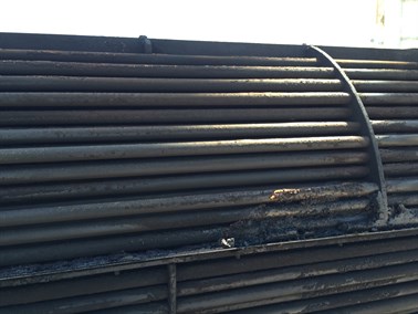
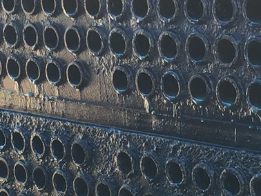
A natural gas processing plant with two condensate stabilizers in South Texas, U.S, was experiencing challenges with fouling in the heat exchangers at both stabilization units. Substantial fouling was observed on both sides of the heat exchangers at both units, affecting more significantly the tube side of the exchangers. These vessels exchange heat between the feed condensate to the stabilizers (tube side) and the bottoms stabilized condensate from the reboilers (shell side). The exchangers with observed fouling at both units were the last of two in series. Tube-side flow blockages (FIG. 3) required shutdowns for cleaning and bundle replacements as frequently as once per week. Fouling was also suspected in the first heat exchangers and the stabilizer reboilers.
 |
 |
|
FIG. 3. Heat exchanger bundle after removal: Shell-side fouling (left) and tube-side fouling (right). |
|
FIG. 4 shows a simplified process flow diagram of the feed to both stabilizer units, and the exchangers where fouling was observed are highlighted. Condensate from two inlet separators was split to the two stabilizer units and sent to heat exchangers upstream of the three-phase separators. Condensate from each three-phase separator was then sent to two exchangers in series to take heat from the stabilizer bottoms prior to entering the tower. Offgas from the two inlet separators and two three-phase separators was comingled, compressed, chemically treated for H2S removal, and sent to a vertical separator for further liquids removal. The offgas was sent to the gas plant, and any liquids that dropped out in the vertical separator were routed back to the front of the liquid side of the plant for processing along with the feed condensate from the field. Overflow from liquids and pigging tanks was also sometimes routed to the stabilizer feed.
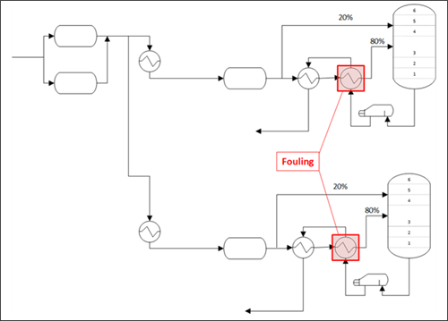 |
| FIG. 4. Process flow diagram of the stabilizer feed system. |
The plant was researching potential solutions (e.g., chemical additives to reduce fouling) but to better understand the problem and its root causes before implementing any solutions, the authors’ company was contacted to evaluate the fouling problem. Company personnel were onsite on two occasions to collect data, discuss historical events with plant personnel, and collect samples for inspection and analysis. Initial sample collection (FIG. 5) and analysis revealed that the feed and stabilized condensate contained little to no solids, but some haze and a ~1% free water phase was observed. However, the water from the separator upstream of the exchangers was heavily contaminated with black solids, suggesting that condensate quality varied significantly or that solids were precipitating and transferring to the water phase as the feed was heated.
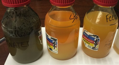 |
| FIG. 5. Three-phase separator water (left), stabilized (middle) and feed (right) condensate. |
Fouling tests were performed on the samples in FIG. 5, but the fouling rate for each of the samples was relatively low. The fouling test results suggested that fouling occurred under certain transient and specific conditions or that additional contamination besides small aqueous carryover was responsible for the fouling problem. To determine whether fouling was occurring consistently or on a transient basis, the exchanger was modeled to calculate the fouling factor over time. The fouling factor is a measure of heat transfer efficiency, and an increase in fouling factor indicates that heat transfer was reduced due to fouling of the exchanger. FIG. 6 shows the fouling factor calculated over the period of the evaluation.
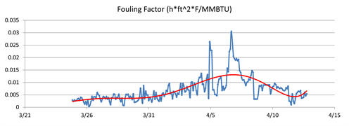 |
| FIG. 6. Calculated fouling factor for the heat exchanger over time. |
It can be observed from FIG. 6 that the fouling factor began to rise more rapidly at the end of March, indicating a rise in contamination ingression and fouling. The fouling rate began to decrease and cease completely as the fouling factor stopped increasing; in early April, the fouling factor actually declined. The decline in fouling factor suggests that heat transfer was increasing, therefore foulant was likely being removed from the exchanger and moving downstream to the stabilizer.
It was noted that the liquids from the vertical separator that feeds back to the three-phase separators were black in color and contained a significant amount of solids, similar to the solids isolated from the water boot at the three-phase separator. Solids from this stream were suspected to originate from the H2S scavenger used to treat the offgas, as the scavenger is known to create solid byproducts after reaction with H2S. The pH of the water from the vertical separator was observed to be consistently high (pH 8-9), enough so that the pH of the water within the comingled feed stream was significantly higher than before it was comingled. This pH effect was suspected to be contributing to fouling via the creation of inorganic scale in the condensate feeding the exchangers of concern.
X-ray diffraction (XRD) analysis was performed on a sample of the foulant from the exchanger tubes (TABLE 2). It was determined that most of the deposit was calcium carbonate scale, and thus the potential for precipitation in the feed system was revealed. Salts and formation solids, such as sand/silt/clay, were also present in the deposit, which suggests that ingression of produced water with the feed promotes fouling.
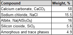 |
| TABLE 2. Results of XRD analysis of solids from heat exchanger tubes |
To determine the potential for scaling precipitation within the feed system itself, an analysis of water from the feed was conducted. Components that contribute to scaling were first quantified, and it was determined that the feed condensate water contained extremely high levels of bicarbonate and carbonate, as well as calcium and magnesium hardness that could contribute to scaling. Iron, sodium and other ions that could precipitate to form salts were also detected at high levels. The scaling tendency of the sample was also determined. A common measure of the scaling tendency of a water sample is the Stiff-Davis stability index, which is a measure of the saturation of calcium carbonate in water samples. The index value is defined as the difference between the sample pH and its pH at saturation. Positive values indicate scaling tendency, and acid treatment can be used to move the index to a negative value to prevent calcium carbonate precipitation. FIG. 7 shows the Stiff-Davis stability index values for the feed condensate water sample at varying temperatures.
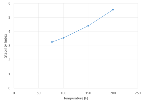 |
| FIG. 7. Stiff-Davis stability index values for the feed condensate water. |
FIG. 7 clearly indicates that the stability index not only has positive values, but an increasing value with increasing temperature. This increase is indicative that calcium carbonate is less soluble as temperature increases and more prone to precipitation. If water from the separator was carried over to the downstream heat exchangers, the increase in temperature was likely to cause scale formation. FIG. 7 also shows what degree of an acid treatment would be required to prevent scaling: for example, the pH would need to be lowered by 5.5 to prevent calcium carbonate precipitation at 200ºF.
The findings from sample analysis suggested that removal of all produced water entrained with the feed condensate was critical to prevent scaling. To determine whether the three-phase separators were designed properly and identify potential improvements to remove water, the vessels’ design and operating window were evaluated. It was determined using Stokes’ Law with the vessel dimensions, liquid levels, flowrate and fluid properties that the vessels would not effectively remove water droplets at sizes of 270 microns or less due to the low residence time and vessel volume available for separation. The main deficiency was the vessel size; the effective settling zone residence time was 6.3 min at the normal flowrate, but at least 20 min would be required for effective separation of 150-micron droplets, as recommended for gravity settling separators.
Furthermore, it was determined that the feed condensate and water had very low surface tension and created a tight emulsion upon mixing, so the majority of entrained water was expected to be present at droplet sizes below 100 microns. It was noted that the feed condensate to the separators contained about 1% water and the effluent condensate still contained as much 0.5% water.
All of the testing and analytical data indicated that the fouling material was scaling of inorganic salts in the heat exchanger along with some deposition of upstream formation solids. These inorganic components were associated with produced water entering the heat exchangers as free or emulsified water. Little to no thermally induced organic polymerization fouling or other mechanism was detected. The primary recommendations made to reduce fouling were therefore aimed toward improving water separation upstream of the heat exchangers. Improved separators as well as pilot testing of a coalescer were recommended, and increased liquid level setpoints in the current separators were suggested as an alternative. The use of an emulsion breaker was also recommended due to the high level of surfactant contaminants stabilizing emulsions. It was additionally recommended to divert liquids from the offgas vertical separator elsewhere or treat the stream prior to comingling with the condensate feed, as this stream was likely causing pH and additive-induced precipitation and fouling. An anti-scaling additive was also recommended to mitigate precipitation of any contaminants that reach the exchangers. The plant improved separation at the inlet separators, and after water was being removed effectively, fouling rates decreased significantly.
Takeaways. This case highlights the importance of monitoring for fouling precursors not only in the primary phase of the feed, but also in the secondary phase. Little to no fouling tendency was observed in the condensate itself; however, precipitation occurred when associated water was present. Analysis of the condensate or the solids in the feed would not reveal any potential for fouling issues, but the root cause of the issue and the best possible solutions were revealed after identifying dissolved fouling precursors in the water phase. It is also critical to understand why contamination is present: it was possible to improve water removal only after determining that the condensate and water contained surfactants imparting high emulsion tendency and must be treated differently to accommodate effective separation.
Part 2 of this article, which will appear in the February issue, will discuss further case studies and solutions to the challenges presented there. GP
NOTES
a Nexo Solutions’ GASCO small-scale testing unit
 |
DAVID ENGEL is the Managing Director for Nexo Solutions and a PhD chemist with more than 20 yr of industrial experience in a variety of areas ranging from chemical synthesis to phase separation technologies. Dr. Engel is the inventor in 21 U.S. invention patents on various subjects relating to technology development for sensors, nanotechnology, coatings, pharmaceuticals, pipeline systems, chemical additives and separation technology. He has also presented a number of seminars on a variety of technical subjects throughout the Americas.
 |
SEBASTIAN ENGEL is the Laboratory Manager at Nexo Solutions and has extensive expertise in chemical consulting and laboratory analysis. He is responsible for laboratory services, including testing, quality control, research and development, sample analysis and customer support. Engel has conducted chemical analyses that have successfully discovered and characterized contaminants found in many different industrial processes. He studied chemistry at Sam Houston State University.
 |
SCOTT WILLIAMS is a Senior Process Engineer at Nexo Solutions and has industry experience in many projects in oil and gas, chemical and water treatment applications. As part of the engineering group, Williams is responsible for onsite testing, troubleshooting and process optimization at various plants and provides support for contamination control technologies and analytical projects. His recent work has been focused on feedstock contamination control, debottlenecking and asset protection. Williams holds a BS degree in chemical and biological engineering from the University of Colorado at Boulder.
 |
CODY RIDGE is a Lead Process Engineer at Nexo Solutions and is responsible for field engineering and technology development, as well as process optimization and operational support. His recent projects include feed gas conditioning systems and root cause determination for contamination. Ridge is a chemical engineer from Texas Tech University and has worked as an operator and process engineer in the Permian Basin.


Comments