
Simplified simulation model for an LNG terminal
The natural gas liquids/liquefied natural gas (NGL/LNG) value chain encompasses the production, processing and liquefaction of natural gas (NG) to LNG, its long-distance transportation, and its regasification as it travels from the wellhead to end users. An LNG terminal is an important part of the NGL/LNG value chain and is used at the final stage to unload LNG and distribute NG to users.
Considering that approximately half of the total cost of an LNG terminal project comes from equipment and critical lines, the finalization of the facility’s capacity and equipment size verification are critical during the bidding stage. In general, 30–40 operating cases exist in an LNG terminal, so reviewing and checking all operating cases are time-consuming tasks.
This article will focus on the application of a shortcut rigorous simulation model1 for front-end engineering design (FEED) to ensure the optimum design for cost estimation during the bidding stage to secure competitive advantage.
Operating cases in an LNG terminal. Operating cases in LNG terminals are based on various factors, such as LNG composition [lean/rich/high nitrogen (N2)], ship unloading status (unloading/holding—no unloading), NG send-out flowrate from the terminal (maximum/minimum/zero), send-out condition (high-pressure, low-pressure), ship loading rate from the LNG terminal (if the ship loading provision is considered), etc.
With the above prescribed conditions, various required operating cases are summarized here:
- Ship unloading minimum and zero send-out case (lean/rich/high N2)
- Ship unloading maximum send-out case (lean/rich/high N2)
- Ship unloading normal send-out case (lean/rich/high N2)
- No ship unloading (holding) minimum and zero send-out case (lean/rich/high N2)
- No ship unloading (holding) maximum send-out case (lean/rich/high N2)
- No ship unloading (holding) normal send-out case (lean/rich/high N2)
- NG battery limit send-out pressure (high/low).
Given these conditions, some 40–50 operating cases must be evaluated. The results should be reviewed to determine the governing case with a different combination of all equipment and associated connected lines.
For the normal specification above, additional scenarios must be studied if specified in an invitation to bid (ITB) document, such as:
- Additional operating cases might be needed for two unloading jetties
- Phase II expansion or any interaction with an existing LNG terminal.
Traditional simulation. To meet the above-mentioned requirement, simulation is the first priority. A traditional simulation model requires various input changes and external calculation assistance for simulating various cases. LNG tank and ship boil-off rates are calculated externally as per client information in the contract and used as an input for the simulation model. Some cases only call for a change in input data; however, for a few operating cases, the structure of simulation model must also be modified.
Input for the general simulation model. The following are the general simulation input/changes required for each simulation case, regardless of unloading/holding mode operation:
- LNG ship and LNG tank unloading/holding mode boil-off rate is calculated externally and used as a simulation input for concerned operating mode cases.
- LNG composition must be input into the simulation model manually based on the considered LNG composition.
Unloading mode. A change required for an unloading mode case is:
- Generally, the unloading mode simulation model is prepared first and used as a basis for preparing further operating cases, including the holding mode.
Holding mode. Considering the unloading mode simulation model is available, the following changes are required for the holding mode simulation model:
- Calculate the ship and LNG tank boil-off based on holding mode operating conditions.
- Stop boil-off gas (BOG) flow from LNG tank to ship.
- Divert the required part of flow from the low-pressure (LP) LNG pump to the unloading line to keep cool purpose.
- Change the controller setting in the simulation model for estimating keep cool flow.
- In circumstances with more than two LNG tanks, ensure proper keep cool LNG flow distribution among LNG tanks based on hydraulics.
- Change LNG tank operating pressure.
For the nine steps mentioned above, > 20 input changes are required besides the actual structure changes in the simulation model.
Simplified simulation model. Critical sections of the LNG terminal simulation model are discussed here to demonstrate the usefulness of automation. By adopting the described approach, users can extensively reduce the input changes required for switching between various operating cases. Users should note that an increase in automation also increases the complexity of the model. With these options, the working time of simulation decreases significantly. Additional automation can be communicated, if needed; however, more automation may increase the convergence issue, and also occasionally increases convergence time. This should be decided case by case. Note: General simulation means that no optimization tool or programming are used.
COMMON SIMULATION CHANGES FOR UNLOADING/HOLDING MODE
Ship boil-off. With the help of simple coding, ship boil-off is calculated in simulation by linking actual stream properties. The tutorial codea is used inside the calculator block BOG-SHIP in FIG. 1 (SHIP & BOG RETURN section). Procedure 1
for ship boil-off (for calculator block “BOG_SHIP”) is below:
$C1: Ship boil-off: VAP vol%/d for QMAX ship (0.15 vol%)
$C2: QMAX ship volume (266,000 m3)
P(1): Consider LNG stream actual density (kg/m3)
P(2): Consider BOG stream actual density (kg/m3)
Part 1: R(1)=C(1) × C(2)/100/24 × P(1)
Part 2: 10 IF (P(3).GT.10000) then,
20 R(2)=R(1)/P(2)
30 else
40 R(1)=14000 × P(2)
50 end if
Return
Code description. In Part 1, LNG ship boil-off is calculated based on actual case density. Part 2 is one of the multiple steps for switching unloading mode to holding mode. In this step, ship boil-off was increased to ensure no BOG return to ship; as during holding mode operation, SHIP is not present. C represents the “constant” that can be specified by the user; P represents the “parameter” that can be extracted from the simulation model; and R represents the “calculation results” that are used in further modules.
LNG tank boil-off. LNG tank boil-off is governed by many factors. In general, manual input is required for various cases. However, with the help of a simple program, all boil-off calculations are automated and external calculation assistance is no longer required. Refer to calculator Block “TK_HL + PL” in FIG. 1 (LNG TANK section). Procedure 2 for LNG tank boil-off (for calculator block “TK_HL + PL”):
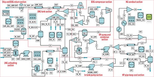 |
| FIG. 1. A typical simplified LNG terminal simulation model. |
$C1: Tank height
$C2: Tank diameter
$C3: Tank thickness (50+16)/2 = 33 mm
$C4: Tank material density
$C5: Metal heat capacity
$C6: Five sets of tanks
P(1): LNG density (kg/m3)
P(2): Enthalpy of BOG (Kj/kg)
P(3): Enthalpy of LNG (Kj/kg)
P(4): LNG unloading flowrate to LNG tank (m3/hr)
Part 1: R(1) = P(2)-P(3)
Part 2: R(2) = 3.14159 × C(2) × C(2)/4 × C(1) × P(1) × 0.05/100/24 × R(1)/1E6 × C(6)
Part 3: R(3) = 3.14159 × (C(2) + C(3)) × C(3) × C(4) × (P(4)/(3.14159 × C(2) × C(2)/4)) × C(5) × 4/1E6
Part 4: R(4) = R(2)/R(1) × 1E6
Part 5: 10 if (P(1).GT.10000), then
20 R(5) = R(3)/R(1) × 1E6
30 else
40 R(5) = 0.001
50 end if
Return
Code description. Part 1 details the latent heat calculation; Part 2 addresses heat duty corresponding to LNG tank boil-off; Part 3 covers heat duty that corresponds to incremental cooling of LNG tank plate due to an increase in tank level; Part 4 covers BOG flow—tank boil-off (based on ITB boil-off rate); and in Part 5, this part of the code is used to give a startup value of BOG return to ship to improve convergence time. Heat duty calculated in Parts 2/3 is imparted to a flash that represents the LNG tank.
LNG composition must be input based on various operating cases. In a simulation softwareb, “upstream utility” is used to input all LNG compositions once. This utility offers dropdown selection for LNG composition, saving the time to input LNG composition for each case (FIG. 2).
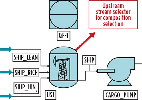 |
| FIG. 2. LNG composition must be input based on various operating cases. |
Additionally, the whole calculation blocks are created for the send-out section to reduce manual intervention. Refer to the typical simplified LNG terminal simulation model in FIG. 1 for an overview of the overall simulation model.
Takeaway. The simulation model proposed here is an adaptive and helpful way to conduct quick simulation on the required simulation cases, with a selector button from data specified in the calculator block in lieu of manual input. This allows various operating cases to become more flexible and adaptive. Also, the results can be studied easily and enables better cost estimation during the bidding phase when delivery of proposal timing is challenging. GP
NOTES
a Fortran Language Quickstart tutorial
b AVEVA’s PRO-II Simulation software
LITERATURE CITED
- Tavares, F. B., T. Mitro, N. Maennling and P. Toledano, Columbia Center on Sustainable Investment, “Manual for the open LNG regasification model,” October 2018, online: https://ccsi.columbia.edu/sites/default/files/ content/docs/our%20focus/extractive%20industries/LNG-Import-Model-Manual-CCSI-2018.pdf
 |
JIN-WEN CHANG is a Process Expert within the process department of CTCI Corp. He has 35 yr of experience in the refining, petrochemical and chemical industries. Dr. Chang earned a PhD in chemical engineering from the National Taiwan University of Science and Technology. He is also registered engineer in Taiwan.
 |
DATTATRAY KOLTE is a Senior Process Engineer for CTCI Corp.’s hydrocarbon business operations. He has more than 15 yr of experience in the LNG, refining and petrochemical industries. Mr. Kolte earned a BTech degree in chemical engineering from UDCT–Jalgaon, North Maharashtra University, India.


Comments