
Decarbonize LNG liquefaction with pre-combustion CO2 capture technology
In recent years, lifecycle greenhouse gas (GHG) emissions studies of the natural gas industry have drawn attention to the significant environmental impact of liquefied natural gas (LNG). Not only is carbon dioxide (CO2) released when natural gas is burned at the end user, but the processes of extracting, treating, liquefying, shipping and regasifying the natural gas all contribute to the total emissions of using natural gas as fuel. With natural gas representing a rising fraction of the world’s total energy consumption, the importance of reducing these emissions will continue to grow in the future.
Emissions from end users occur across many different geographic locations, from large-scale power generation facilities to individual homes. For many of these users, capturing and sequestering the CO2 associated with their emissions is challenging for various reasons (economics, lack of sequestration infrastructure, etc.). Conversely, LNG liquefaction facilities present a unique opportunity to capture GHG emissions, as they provide a single location where a significant portion of emissions is concentrated.
For both retrofits to existing plants and for new-build plants, pre-combustion CO2 capture can significantly reduce the overall carbon footprint of LNG. This article examines how a proprietary approach to implementing and integrating pre-combustion capture with an LNG liquefaction facility can reduce the overall CO2 emissions from a liquefaction facility by more than 97%. This approach comprises the following three main steps:
- Producing hydrogen (H2) fuel from natural gas or other fuel gases within the liquefaction facility
- Removing CO2 from the syngas generated during H2 production
- Using the H2 as the primary fuel in the plant’s gas turbines.
The details of this configuration are flexible and can be adjusted to serve individual project needs.1–5
Methods to reduce CO2 emissions. CO2 emissions at an LNG liquefaction facility can be categorized into three primary sources:
- CO2 vented during upstream pretreatment to remove acid gases
- CO2 released in the flue gas from gas turbines used to power the liquefaction process
- CO2 released in the generation of power for the remainder of the facility.
Two broad approaches can be utilized to reduce the CO2 emissions from these sources. One approach is to reduce the amount of CO2 generated, primarily by improving efficiency. The second is to capture and sequester the CO2 in the feed and the CO2 created during power generation. A combination of both approaches is necessary to achieve a high degree of overall emissions reduction.
Capturing and sequestering the CO2 in the feed is already possible with well-proven technologies. A typical acid gas removal unit (AGRU) for LNG already separates CO2 from the natural gas feed using an amine-based absorption process. Although many facilities today reject that CO2 to atmosphere, some already possess the capability to capture CO2 removed this way and sequester it. The use of this approach can reduce the total CO2 emissions from an LNG facility by up to 30%, depending on the amount of CO2 found in the feed.
Improvements to plant efficiency can also reduce CO2 emissions. Although many LNG facilities use simple-cycle industrial gas turbines, newer facilities have made use of aeroderivative gas turbines or combined-cycle arrangements to improve power efficiency. With improved power efficiency, less fuel is required to generate the same power available for liquefaction. This results in lower emissions for the same LNG production. The use of aeroderivative turbines can potentially reduce the CO2 emissions of a facility by approximately 14% over equivalent industrial gas turbines, while a combined-cycle arrangement can reduce CO2 emissions by approximately 25% over a simple-cycle arrangement.
While these existing methods can significantly reduce the amount of CO2 released from a facility, they cannot address all the CO2 released in the flue gas from a plant’s gas turbines. To capture the remaining CO2, a different approach is required.
Flue gas CO2 reduction via pre- or post-combustion capture. Two potential approaches to reduce CO2 emissions from methane-burning gas turbines are post-combustion capture and pre-combustion capture.
With post-combustion capture, shown in FIG. 1, air and methane-rich fuel are fed to the gas turbine and CO2 is directly removed from the flue gas by a CO2 capture system. In this configuration, CO2 is available at low partial pressure (near-atmospheric pressure with single digit mol% of CO2) and high temperature. These conditions make it challenging to design a cost-effective recovery system that captures most of the CO2. Furthermore, in retrofit applications, the lack of plot space close to the gas turbines can be problematic. The low pressure and high volume of flue gas may be impractical to transport to a distant CO2 recovery unit.
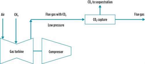 |
| FIG. 1. Generic configuration for post-combustion CO2 capture. |
Conversely, pre-combustion capture, shown in FIG. 2, captures CO2 from streams at higher pressure and with higher fractions of CO2 (20%–30%). Pre-combustion capture needs a far smaller CO2 recovery unit but requires other additional equipment to process the hydrocarbon fuel gas into clean H2 for use in the gas turbines. Although not directly used for LNG service, the required technology for pre-combustion capture has been used for decades. For example, the authors’ company’s Port Arthur CO2 capture project has captured approximately 1 MM metric tpy of CO2 from two large-scale H2 plants since it commenced operations in early 2013.
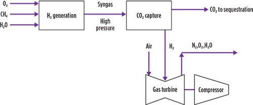 |
| FIG. 2. Generic configuration for pre-combustion CO2 capture. |
The advantages of pre-combustion capture allow for easier retrofit into existing plants and easier siting of the additional equipment needed for CO2 capture. The proprietary pre-combustion capture processa uses a pre-combustion approach to capture the CO2 that would be released in the gas turbine flue gas.
Pre-combustion capture technology overview. The proprietary process consists of three major systems (shown in FIG. 3):
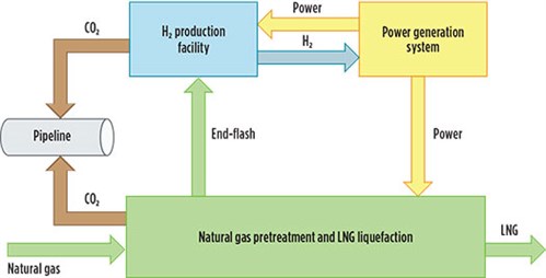 |
| FIG. 3. Proprietary pre-combustion capture technologya layout overview. |
- The LNG liquefaction plant, including pretreatment
- The H2 production facility
- The power generation system.
The LNG liquefaction plant takes in raw natural gas feed. Gas pretreatment, including acid gas removal, mercury removal and any heavy component removal, occurs upstream of the liquefaction plant. The liquefaction plant produces LNG from the pretreated gas while also producing a fuel stream that consists of end-flash and boil-off gas. Normally, this fuel stream would be sent directly to the gas turbines to generate power. However, in the proprietary pre-combustion capture process, the fuel gas stream, which is primarily methane (CH4) and nitrogen (N2), is instead sent to an H2 production plant. The specific technology used for H2 production can vary; potential options are discussed below.
In the H2 production facility, the fuel gas stream is combined with oxygen (or air) and steam. The combined stream is sent to a series of reactors to generate a syngas stream of primarily H2 and CO2. The syngas stream contains CO2 at high pressure (> 30 bar) and at a high fraction of the total stream molar flow (20%–30%). These conditions are well suited for CO2 separation from H2 product at moderate cost.
CO2 is removed at two points in the process. First, the CO2 in the natural gas feed is removed in the AGRU. Next, CO2 generated during the reforming and water-gas shift reactions within the H2 production facility is removed during a downstream separation step. This separation can be achieved through an amine unit similar to the AGRU, or through vacuum swing adsorption (VSA), cryogenic distillation or other techniques. Several of these technologies can achieve the target of > 97% CO2 recovery.
After CO2 removal, H2 from the production facility is combined with CH4 or used as pure H2 fuel. The fuel is mixed with one or more diluents to suppress nitrogen oxide (NOx) formation and is sent to the power generation system, which produces power for liquefaction and the H2 production facility.
The power generation system may be simple or combined-cycle, and it may either be directly coupled to the liquefaction compressors or instead coupled to generators to produce electricity used by electric motors in the liquefaction facility.
Hydrogen production facility options. The pre-combustion capture processa can use a wide variety of technologies for its H2 production plant, including the steam methane reforming (SMR) process, the autothermal reforming (ATR) process, or the partial oxidation (POX) process. All three options include a main reactor, one or more water-gas shift reactors, and several heat exchangers for steam generation.
The SMR process uses a tubular catalytic main reactor where fuel is burned at low pressure externally to the tubes to provide the heat needed for the reforming reaction. The SMR process is an industry standard for gray H2 production thanks to its energy efficiency, high reliability and attractive capital cost. However, because fuel is burned at low pressure, approximately 40% of the total CO2 generated in the H2 production facility is released in low-pressure flue gas and cannot be recovered through pre-combustion capture.
The POX and ATR processes instead provide the required heat for their reactions by reacting a portion of the feed stream within the reactor vessel. This allows all CO2 formed during the reactions to remain within the high-pressure stream exiting the reactor. The CO2 can then be removed from the product stream by an amine system or other separation technology, enabling a high degree of carbon capture for both processes. The differences between the two technologies lie with the specific reactions involved and the type of reactor needed. The POX process uses a non-catalytic main reactor and uses steam for temperature control, while the ATR process uses a catalytic main reactor with steam consumed as part of the reaction.
TECHNOLOGY SYNERGIES
The pre-combustion capture processa features several synergies gained by integrating liquefaction, H2 production and power generation. These synergies would be unavailable if a plant were designed to run on green electricity from a local grid, or if it imported H2 for its gas turbines.
Improved liquefaction efficiency. The proprietary process allows for a re-optimization of the LNG liquefaction plant to improve efficiency. Higher fuel requirements for the H2 production facility allow for increased end-flash flow from the liquefaction facility, potentially increasing LNG production by up to 2%. This may aid in debottlenecking existing facilities that would otherwise be limited by available liquefaction power.
Low gas turbine NOx emissions. With H2-burning gas turbines, a major concern is the generation of NOx. The pre-combustion capture process has several features that help in maintaining equivalent levels of NOx to a typical dry low emissions (DLE) system. In the process, the end-flash gas used to feed the H2 production plant typically contains a significant fraction of N2. This N2 passes through the plant and is sent to the power generation system, where it serves as a diluent for the fuel and aids in suppressing NOx formation. Excess steam and N2 from the H2 production facility are also available for use as additional diluents.
Retrofit considerations. The process can be applied at both new-build sites and in the retrofit of existing plants. Retrofitting an existing plant to decarbonize it comes with several unique challenges and opportunities, as discussed here.
Gas turbine capabilities. Many gas turbines used as compressor drivers for natural gas liquefaction can handle a fuel that consists of a mix of H2 and CH4, requiring only minor engine and package upgrades to ensure safety and reliability while appropriately handling the new fuel. However, for cases where the goal is a high degree of pre-combustion carbon capture, the gas turbine must be capable of handling fuel with a combustible component comprised of 100% H2. Some turbines have already been designed for 100% H2 fuel. For other existing turbines, running on this fuel requires a modification of the combustion system to manage the unique properties of high-H2 fuels. In either case, the gas turbine and other site specifics—including emissions limits and utilities availability—must be considered when evaluating H2 as a fuel.
Offsite H2 facilities. At some sites, there is insufficient nearby plot space for an H2 production facility. In these cases, it may be possible to export end-flash gas via a pipeline to a remote H2 production facility and receive either H2 fuel or electricity in return. Alternatively, an existing LNG facility may simply wish to replace a portion of its fuel with a decarbonized fuel from a third party without any major changes to its own facility. Purchasing decarbonized H2 from an external source is a simple change that can decrease an LNG facility’s carbon footprint.
CASE STUDIES
The following section examines three case studies implementing the proprietary pre-combustion capture processa, two retrofit options for existing plants and a new-build that takes full advantage of both efficiency improvements and CO2 capture options.
All three cases and the base case used for comparison assume an LNG liquefaction facility that uses a proprietary LNG technologyb. This plant has net-in-tank LNG production of 4.5 MMtpy. The raw natural gas feed to the liquefaction plant pretreatment contains 4% CO2, which is removed in the AGRU. Unless otherwise stated, the liquefaction power is provided by two directly coupled industrial gas turbines (Frame 7E) in simple-cycle, and an industrial gas turbine as a simple-cycle power generator for the electrical power requirements. For the purposes of this case study, the power generator can be another single Frame 7E, or multiple smaller gas turbines of similar efficiency and total power capacity.
For each case, the power used by liquefaction is held constant, while the total power was varied to address the power needs of the additional H2 production facility.
Retrofit (partial and full) cases. Two options were evaluated for the retrofit case, differing on the degree of upgrades needed for the combustion system of the gas turbines. The “partial H2” case sends a portion of the flash gas to the H2 production facility, then recombines the H2 product with the remainder of the flash gas. This resultant fuel stream contains approximately 20 vol% H2. Existing industrial gas turbines designed for use with natural gas require only minor adjustments to handle this new fuel stream, which avoids a significant overhaul or extended downtime.
The “full H2” case sends all the flash gas to the H2 production facility, generating a fuel stream of predominantly H2 (with N2 or steam as diluents). Although some industrial gas turbines are capable of handling such a fuel stream, these turbines may require a conversion of the combustion system and fuel delivery system modifications to do so.
In both options, additional gas turbine generators are required to supplement the existing electric power. These can be located at the H2 production facility.
New-build case. The new-build case examines a potential new LNG liquefaction facility. This hypothetical plant utilizes three aeroderivative gas turbines in combined-cycle for power generation, as well as one or more small gas turbine generators to supplement the available power. Electric motors driving the liquefaction compressors use most of the generated power. The remaining power is used for the balance of plant. Liquefaction compressor power has been fixed at the value used for the base case for ease of comparison.
For all three cases, the following additional technology selections were made:
- High-conversion POX process for H2 production
- Air separation unit (ASU) to provide low-purity gaseous oxygen for POX
- AGRU designed to recover CO2 and compress to pipeline pressure
- Amine unit integrated into the H2 production facility to separate CO2 from the H2 product.
The results for each case are shown in TABLE 1.
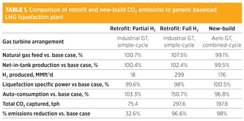 |
Takeaways. In the retrofit cases, the higher flash gas demand improved the liquefaction specific power—the liquefaction compression power required to produce 1 metric t of LNG—allowing more LNG to be produced for the liquefaction power. The partial H2 case achieved 0.4% higher production, whereas the full H2 case achieved 2.4% higher production. For the new-build case, a more efficient gas turbine selection reduced the flash gas requirement and slightly reduced the LNG production.
However, the new-build case’s efficiency provides significantly better auto-consumption—the percentage of feed consumed as fuel—than the retrofit cases. The new-build case also requires a significantly smaller H2 production facility for a similar liquefaction plant to achieve 97% emissions reduction. The overall CO2 generated during H2 production is also significantly lower for the new-build case compared to the full H2 retrofit, which reduces the required size of the CO2 compression system.
Both retrofit and new-build cases are capable of a high degree of overall CO2 capture by capturing CO2 from the natural gas feed and by pre-combustion capture of the CO2 generated in the H2 production facility.
The partial H2 retrofit case achieved a CO2 emissions reduction of 32.6%, an improvement over capturing CO2 from the AGRU alone. Due to the modest H2 requirement for this case, one H2 plant can serve multiple LNG trains. The primary advantage of this case is its compatibility with existing gas turbines with only minor upgrades.
The full H2 retrofit and new-build cases achieved CO2 emissions reductions of 96.6% and 98%, respectively. These cases show how existing and new plants may achieve a high degree of emissions reduction, though both require significant changes to the gas turbines to accommodate high-H2 fuels. Both cases show how the pre-combustion capture technologya provides a pathway to eliminating the carbon footprint of natural gas liquefaction. GP
NOTES
a Air Products’ AP-Blue™ LNG
b Air Products’ AP-C3MR™
LITERATURE CITED
- Mallapragada, D. S., E. Reyes-Bastida, F. Roberto, E. M. McElroy, D. Veskovic and I. Laurenzi, “Life cycle greenhouse gas emissions and freshwater consumption of liquefied Marcellus shale gas used for international power generation,” Journal of Cleaner Production, 2018.
- Ott, C. M., J. D. Bukowski, R. Shnitser and J. Dunn, “Efficiency, low CAPEX nitrogen removal for natural gas liquefaction,” Gastech 2021, Dubai, September 21, 2021.
- Saunderson, R. P., “End-flash is totally cool,” Hydrocarbon Engineering, May 2021.
- Folger, P., “Carbon capture technology assessment: In brief,” U.S. Congressional Research Service, R43300, November 5, 2013.
- Dewing, R., V. White and J. Hicks, “Hydrogen plants with CO2 capture: Retro-fit options and practical considerations,” 15th International Conference on Greenhouse Gas Control Technologies (GHGT-15) Abu Dhabi, UAE, October 5–8, 2020.
 |
DEJAN VESKOVIC joined Air Products in 2011 as part of the Air Products HyCO business, supporting process safety and plant operations. He now works as a Principal Process Engineer in the LNG Process group, where he has designed and developed LNG plants with a range of liquefaction technologies, as well as supported the startup and performance testing of those plants. He received his BS and MS degrees in chemical engineering from Pennsylvania State University and Villanova University, respectively.
 |
JEREMY D. BEARD is a Lead Machinery Engineer in the Process Gases Group at Air Products and Chemicals Inc., supporting both the development and execution of new projects related to the production of blue H2 through carbon capture, utilization and storage. Mr. Beard has also provided machinery support to other groups within Air Products in the development of projects and process technology in LNG, syngas and other products. He received his BS degree in mechanical engineering from Louisiana State University.
 |
MARK ROBERTS joined Air Products in 1996 and has more than 30 yr of experience developing cryogenic cycles for gas separation and liquefaction in the air separation, hydrocarbon processing and LNG industries. He has more than 40 U.S. and international patents issued in his name, including the patents for the AP-X™ liquefaction process used for the six mega-trains in Qatar, the patent for the AP-N™ liquefaction process deployed in the first offshore project, Petronas FLNG Satu, and the patents for the AP-DMR™ dual-mixed refrigerant liquefaction process used on the Coral South FLNG vessel under construction.
 |
DAVE GRAHAM is a Research Engineer at Air Products and Chemicals. He has worked in the areas of H2 production, air separation, LNG and carbon capture during his 22-yr career. Dr. Graham earned a BSE degree from the University of Michigan, and MS and PhD degrees from the University of Illinois.


Comments