
Lessons learned to optimize flare gas recovery systems in gas plant operations
There are more than 100 flares spread across many operating facilities in the upstream and downstream oil and gas processing plants of Saudi Aramco. Flare systems are designed to provide the safe disposal of hydrocarbons that are either automatically vented or manually vented from process units. Flare systems gather vented gases and combust them to prevent release directly to the atmosphere.
Since Saudi Arabia started producing oil, associated gas has been flared. In the 1970s, the Kingdom recognized the value of the associated gas produced with crude oil. Major investments in building a sizable master gas system resulted in capturing and utilizing all the associated gas instead of burning it in gas flares. As a result, the Kingdom’s annual flaring has been considerably reduced to facilities’ routine and emergency flaring only. The environmental regulations from Saudi Arabia’s Presidency of Meteorology and Environment require controls for smokeless flaring only from industrial activities, and there are no penalties for carbon dioxide (CO2) emissions.
These standards apply just to routine emissions, and not to emergency, startup or shutdown events. Most Saudi Aramco facilities meet the environmental standard for smokeless flaring. The corporate roadmap on flaring was initiated as a response to the escalating cost of the new project proposals to make flares smokeless for routine operations in all of the company’s facilities. The key element of this roadmap is to minimize flaring by implementing site-specific flaring minimization plans (FMPs) and installing a flare gas recovery system (FGRS) wherever feasible.
An FMP was initiated to reduce flaring from all Saudi Aramco facilities over a defined period by minimizing the frequency and magnitude of flaring. A comprehensive engineering standard for real-time measuring, monitoring, reporting and minimizing flaring was developed. Part of this minimization plan was to study the leakage rate to the flare system and to determine purge optimization. These two analyses play major roles in reducing facility emissions. Furthermore, the company’s Process and Control Systems department issued design guidelines for FGRSs to give clear direction for selecting and applying new FGRS projects in all Saudi Aramco operating facilities. This guideline is in line with the Saudi Aramco corporate decarbonization strategy to reduce greenhouse gas (GHG) emissions.
The company has had several technologies in operation for a few years. Therefore, Saudi Aramco has updated its best practices with lessons learned from the startup and commissioning of compressor and ejector technologies at its facilities. This compilation of information provides additional insights that will enhance designs and proactively address common issues that can arise during the startup and operation of FGRSs at Saudi Aramco facilities.
FGRSs. Corporate management has recognized the need to approve a flaring roadmap, which calls for considering an FGRS if any facility is flaring more than 1 MMsft3d of gas after implementing all flaring reduction measures. An FGRS will eliminate flaring as required for plant safety, provide routine process reliefs and return gases back to the process to prevent any leakages. Although FGRS technology is proven in industry, it was not adopted by the authors’ organization in the past because, during that time, there were no compliance requirements for CO2 emissions and there was a very low price to pay for sales gas. In recent years, however, the situation has changed. In the current industry environment, the primary drivers favoring FGRS projects include:
- Stricter global environmental regulations governing the emissions of GHGs, such as CO2
- Environmental impacts and health effects of harmful emissions, such as nitric oxide (NOx), sulfur oxide (SOx) and volatile organic compounds (VOCs)
- Improved economic returns in recovered flared gas to the value chain, thus saving on plant fuel gas and steam consumption
- World Bank carbon credits for uneconomic FGRS projects, specifically for the elimination of CO2 emissions, which can be traded for monetary gains—thus helping to improve returns on investment (ROIs) for projects
- Increased raw gas production costs, which makes FGRSs more attractive, since these systems recover flared gas and recycle it back to the process
- Rising sales gas costs, making FGRS recovery projects more viable
- Shortage of natural gas in the country
- FGRSs improve the reliability of main flare tips (important for larger-diameter flares that are prone to damage from operation at low daily flaring rates), enabling the main flare to stay in standby mode, which improves its reliability and life, and minimizes the recurring cost of flare tip replacement.
Additionally, one of Saudi Aramco’s key values is citizenship, where the organization has a positive influence in communities and requires a demonstration of social responsibility. An FRGS provides an excellent platform to reflect this company image.
FGRS components. A flare gas recovery installation at an existing plant will consist of four main components. Brief descriptions of these component are below:
1. Compression technology is designed to recover flare gases for reuse in the existing processing facilities.
2. Staging devices safely divert routine flared gases to the FGRS, but not the emergency or abnormal relief loads. FIG. 1 illustrates the integration of an FGRS into the flare system.
3. A nitrogen-generation package is included to supplement existing nitrogen-generation capacity. Nitrogen will be used as a purge gas downstream of the staging device.
4. A control system within the package interfaces with the plant’s distributed control system.
As shown in FIG. 1, the flare gas recovery unit ties into the flare gas header between the knockout drum and the staging device and pulls flare gas from the header whenever flow is detected. Basically, the staging devices enable safe operation of the entire system through sealing the elevated flares and providing backpressure in the flare header, allowing the flare gases to be routed to the FGRS.
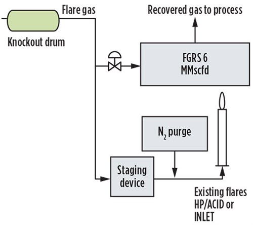 |
| FIG. 1. The integration of an FGRS into the flare system. |
Types of compression equipment. The choice of compression equipment will greatly influence the configuration of an FGRS. A detailed survey of existing technologies revealed that the compressor types widely used for FGRS applications include:
- Liquid-ring compressors with a variety of service fluids (such as water or diesel)
- Multi-staged screw compressors.
The major advantages of these compressor types include:
- They can handle a wide range of gases with varying molecular weights, with no effect on their performance.
- They can handle flow from zero to full capacity with a robust recycling system.
- They can tolerate liquid in the feed vs. any other type of compressors.
Ejectors. An ejector is a well-known technology for pressurizing gas by using a high motive source. The operating principle of the ejector is the pressure energy in the motive fluid, which is converted to velocity energy by an adiabatic expansion in the converging/diverging nozzle. Due to the pressure drop of the motive fluid, it will create a low-pressure zone before the mixing chamber. Due to this low-pressure zone, the suction fluid will start to move toward it and mix with motive fluid in the mixing chamber. The mixed fluid will enter the diverging portion of the ejector, where its velocity energy is converted into pressure energy (FIG. 2).
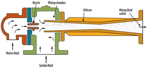 |
| FIG. 2. An ejector schematic. |
The authors’ company has patented this technology to be utilized in a flare system to recover the wasted gas for further treatment or to generate energy. The team conducted several feasibility studies that approved the applicability of this technology to recover flare gas either by using a gas/gas or liquid/gas ejector. This technology was applied in oil-producing facilities and refineries, and it has successfully been used in gas-operation facilities by using amine solution as a motive liquid. When gas at sufficient pressures is available onsite, gas-motive ejectors could be an economical compression solution. Eductors or liquid-motive ejectors can also be considered and may use a closed-loop liquid circulation to provide the needed liquid-motive pressure. Eductors can also be used for gas sweetening purposes.
Recovering flare gas was not stopped by these compression types. The feasibility of flare gas recovery is considered the process philosophy for each facility. For example, each facility can recover flare gas by using an atmospheric compressor. As a result, hydraulic analysis was required to install a jump-over line from the flare header to the compressor suction pipe.
Challenges. Since Saudi Aramco started recovering flare gas, there have been major challenges. However, without these experiences, the authors would not be able to list all the lessons learned to overcome them.
One of the major challenges experienced in FGRSs is the oxygen ingress that resulted in the formation of solid particulates. As a result, these solid particulates blocked the suction strainers of the compressors. A sample was collected and sent to the research and development center for detailed analysis. It was discovered that elemental sulfur composition exceeded 99%.
Normally, elemental sulfur can be found in natural gas processing plants for two reasons: as part of the natural gas mixture coming from the source reservoir, or because of sulfur compounds reacting with oxygen, resulting in sulfur in its elemental form.
In natural gas, elemental sulfur is usually found in the vapor phase. Due to the increased carrying capacity that hydrogen sulfide (H2S) provides to natural gas, its presence in the transported gas mixture helps with transporting elemental sulfur. Compared to methane, H2S can carry more sulfur by three or four more orders of magnitude. Consequently, the probability of sulfur deposition in oil and gas processing facilities is increased.
The desublimation of elemental sulfur at certain pressure and temperature conditions is a major cause for deposition. Usually, the low concentration of elemental sulfur—within the parts-per-billion range—makes it more challenging to detect. In some cases, elemental sulfur desublimates intermittently at certain locations within the plant, causing difficulties in tracking the root causes of the problem.
In addition to elemental sulfur solubility, the oxidation of sulfur compounds could also be a major cause for elemental sulfur deposition. Testing of the demineralized water (in a liquid-ring compressor) indicates that the dissolved oxygen is within the acceptable parts-per-million range. Normally, oxidation of sulfur compounds like H2S leads to the production of sulfur in the elemental form at certain pressure and temperature conditions. However, the source of oxygen is not limited to that in the demineralized water, as it could be air entering the system through leaks, or it could involve the availability of oxygen within the gas mixture transported to the FGRS. Operating the purge gas below the minimum safety requirements can be a major contributor of exposing oxygen in the system.
Also, part of enhancing FGRS reliability is to segregate flare headers with power operated emergency isolation valves (ZVs) should any upset occur in the facility. The FGRS is designed to recover the normal continued flaring; during an upset, the FGRS will be interrupted, resulting in a trip. Therefore, as part of reliability enhancement, the team proposed segregating feed ZV to the FGRS, along with sending a signal to close it in case the pressure in one of the flare headers increases near to the tipping point.
Prior to any change in the flare and relief systems, such as installing a flare gas recovery package, a study of full flare and relief systems should be carried out. Installing a flare gas recovery system could change the constant backpressure in the headers, which would affect the limit on PZVs allowable backpressures. Having the FGRS could also develop new critical overpressure scenarios that would need to be addressed. Further, in many applications, processes are equipped with continuous vent-to-flare systems, either in the process equipment or in the seal gas of the compression systems. Even small changes in operating pressures of the flare headers could lead to process interruptions from these services. Overall, any proposed changes in flare and relief system operations should be first assessed with appropriate studies on these systems. GP
 |
ABDULAZIZ H. AL-TIJANI is an Engineering Specialist at Saudi Aramco’s Process and Control Systems Department in Dhahran, Saudi Arabia. He supports company operations and project design, mainly in flare and relief systems and in flare gas recovery applications. Mr. Al-Tijani also supports Saudi Aramco and JV oil and gas operational facilities, pipelines and process simulations, as well as various phases of projects. He earned a BS degree in chemical engineering from King Fahd University of Petroleum and Minerals (KFUPM), and an MS degree in oil and gas surface facilities from KFUPM (in partnership with IFP).
 |
MAHDI ALDAJANI is a Flare and Relief Systems Engineer at Saudi Aramco. He has 10 yr of experience with Saudi Aramco, working in several Saudi Aramco facilities in support of operations and on detailed design and construction activities on several projects. Mr. Aldajani earned a BS degree in chemical engineering from KFUPM.
 |
ABDULLMAJEED AL-SANAD is a Process Engineer at Saudi Aramco’s Process and Control Systems Department, within the Flare and Relief Systems Group. He has 6 yr of experience, which includes company operations and project support. Mr. Al-Sanad has also participated in a flaring minimization program that included several aspects such as purge gas optimization studies and FGRS evaluations. He earned a BS degree in chemical engineering from KFUPM.
 |
MOHAMMAD AL-MAHMOOD is a Process Engineer at Saudi Aramco’s Process and Control Systems Department, within the Energy Transition Engineering Group. He has 6 yr of experience with Saudi Aramco, which includes company operations and project support. Mr. Al-Mahmood has also participated in the commissioning and process stabilization of an FGRS in one of the company’s gas operation facilities. He has also helped to evaluate FGRS feasibility and energy consumption to identify reliable FGRS applications. Mr. Al-Mahmood earned a BS degree in chemical engineering from Oklahoma State University.


Comments