
Case study: Sour condensate NGL export pumps seal failure
In a facility, a frequent seal failure occurred on two sour condensate natural gas liquids (NGL) export pumps. After dismantling and inspecting one of the seals, it was determined that the seal had high contamination on the inner and the outer seals in addition to high-temperature failure for the outer seal elastomer (dry running seal, mating ring O-ring).
The pump owner reported frequent seal failures and requested pump specialists to oversee a comprehensive investigation. A site visit was conducted by the pump specialists to gain a better understanding of the pump and seal systems.
Additionally, previous seal failure reports were reviewed covering the period from 2014–2017. This case was considered to be an exceedingly high seal failure rate, with a mean time between failures (MTBF) of ~7 mos, considering that only one of the two pumps is typically in operation. This is much lower than the seal design life of 36 mos.
Unit A non-drive end (NDE) seal leak incident investigation. As per the provided data, the Unit A NDE seal failed after less than 1 mos of operation while the pump was not running and resulted in leakage to the atmosphere, triggering the lower explosive limit (LEL) alarm in the plant. The pump was shutdown 7 hr before the alarm. FIG. 1 shows the pump discharge pressure and the seal leakage detection from the time of the pump shutdown to the time where the alarm was triggered.
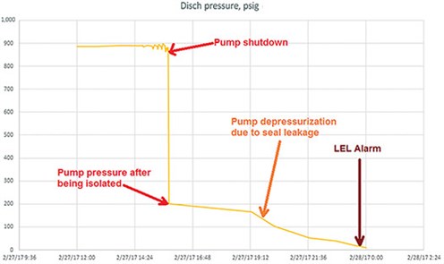 |
| FIG. 1. Pump depressurization due to seal leakage. |
FIG. 2 shows the pressure trend for the drive end (DE) and the NDE seal leakage detection pressure for the complete 23-d duration of the seal operation.
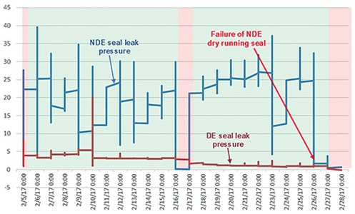 |
| FIG. 2. DE and NDE seal leak pressure measurements. |
The inspection of the seal at a local facility showed the following:
- High contamination on inner and outer seals (FIG. 3)
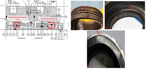
FIG. 3. The outboard mating ring showed heavy contamination and the O-ring was hardened and broken (A and B); the inboard primary dynamic ring showed excessive wear and OD chipping and contamination (C). - Contamination material was partially metallic (i.e., attracted to magnets)
- Inner seal dynamic O-ring had a significant amount of contaminated materials stuck to it
- Outer seal mating ring O-ring was hardened and cut due to high temperature
- Inner and outer seal faces were showing heavy wear marks.
Seal failure analysis. Based on the collected data, the most logical scenarios for the failure of the Unit A NDE mechanical seal are listed here:
- The assessment of the pump’s 23 d of operation shown in FIG. 2 shows that the NDE seal leakage detection pressure maintained an approximate average of 20 psig, which exceeds the alarm limit set at 10 psig. This could be caused by one or a combination of the below:
a. A stuck check valve as per American Petroleum Institute (API) Plan 76. This is highly probable as it might create back pressure in the cavity between the two seals.
b. A passing API Plan 76 drain valve or a passing mechanical seal drain valve. This might result in flow entering the seal cavity.
c. A passing pump drain valve or passing API Plan 23 drain valve. This is also possible and might result in pressurizing the seal cavity if one of its drain valves is passing. - The high seal cavity pressure had a significant effect on the outer seal. This pressure, as well as the high contamination in the process liquid, are believed to have caused the high outer seal temperature, which hardened and broke the outer seal, mating ring O-ring shown in FIG. 3. This resulted in the failure of the outer seal, which is supported by the reduction in the NDE seal cavity pressure from 25 psig to 2 psig (FIG. 2).
- 3. During the operation of Unit A, the pump casing was at a suction pressure of ~200 psig. However, the pressure measurements show that the pump pressure dropped from 200 psig to 5 psig during the 8 hr after the pump shutdown, as shown in FIG. 1. This is believed to be caused by a failure of the NDE inner seal due to hang-up, seal faces wear and/or the presence of dirt between the two seal faces.
Sour condensate NGL export pumps frequent seal failures. A design assessment was completed for the pump system from the suction column to the pump discharge and for the seal auxiliary system to identify any potential design concerns. In addition, the PI process data were analyzed to determine the pump operating conditions. The main points that may have caused the low reliability of the seal are listed here:
- The pump suction line has a permanent strainer with a maximum allowable differential pressure of 0.5 psi. The piping and instrumentation diagram (P&ID) shows that the available net positive suction head available (NPSHA) and the net positive suction head required (NPSHR) are close; therefore, the use of suction strainer is not recommended.
- The pump process data showed that the pumps were operating at a higher differential pressure than the design, as shown in FIG. 4. This was believed to be caused by a higher liquid specific gravity.
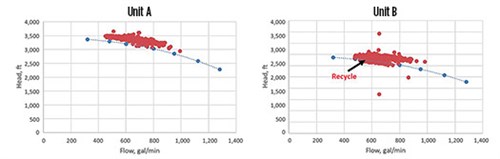
FIG. 4. Unit A and B operating flow and head. - The pumps were consistently operated between 450 gal/min and 900 gal/min (FIG. 4). As the pumps have a best efficiency point (BEP) of ~1,080 gal/min, the pumps were operated for a long time outside the preferred operating region, which ranges from 750 gal/min–1,300 gal/min. This resulted in high flow turbulence and pump vibration, significantly affecting seal life. If an increase in the current process flowrate is not expected, consideration should be given to re-rate the pumps for the actual operating condition. This will help improve pump and seal performance, and reduce pump power consumption.
- The process operating temperature ranges from 260°F–270°F (127°C–132°C), which is higher than the normal operating temperature of 246°F (119°C) specified in the pump datasheet.
- The failure analysis of the final failed seal showed pitting corrosion in critical locations, including O-ring surfaces. A sample of the condensate liquid between the main and backup seals was sent for analysis to identify the cause of pitting. The analysis showed no indication of any major corrosive agents. Pitting may be caused by an isolated incident due to a process upset. If future data shows pitting, material upgrade to duplex or super duplex should be considered.
Seal system design analysis. A design assessment was conducted for the seal design parameters and the seal auxiliary system to identify any potential design concerns. The main points that may have contributed to the low reliability of the seal include:
- The datasheet shows that the liquid specific gravity is < 0.5 with an operating temperature of 246°F (119°C). The pump specialists experienced low seal reliability for many pumps in such applications supplied with vendor seals. Low specific gravity liquids are considered to be difficult to seal. For this reason, API 682 recommends Arrangement 3 seals for liquids with < 0.5 specific gravity, such as this pump with a specific gravity of 0.497.
- The site temperature measurement for seal API Plan 21 flushing liquid during the site visit showed that the inlet and outlet temperatures for the cooler were 176°F (80°C) and 140°F (60°C), respectively. Although this is not in line with the typical process temperature, it shows that sufficient cooling is happening at the cooler. For proper seal performance, pump standards mandate that the stuffing box pressure exceed the vapor pressure by at least 50 psi. This can be accomplished by increasing the stuffing box pressure or decreasing the liquid vapor pressure via cooling methods. In this pump case, the process data indicated that sufficient cooling was provided.
- The seal drawing shows that two 0.125-in. orifices designed to achieve a seal flush flowrate of 3 gal/min were used for API Plan 21. Calculations showed that flowrate will be less than 3 gal/min since the takeoff for API Plan 21 was from the discharge of the first stage. For that reason, the seal vendor was contacted to verify orifices requirements. Based on the vendor response, it was recommended to leave one of the restrictive orifices as it was and to open the other to full bore, as shown in FIG. 5.
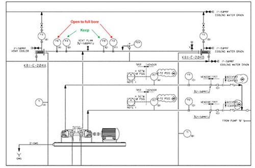
FIG. 5. Location of orifices. - The current seal follows API Plan 76 while company standards mandate API Plan 75. FIG. 6 shows the difference between these two API 682 seal plans. Plan 75 should be used whenever the liquid has heavy ends to prevent the liquid accumulation between the two seals. When Plan 76 is used, the liquid will accumulate between the two seals; this can cause a failure of the dry running backup seal, as it is designed for a gas phase in normal operation. For that reason, it is recommended to change the seal plan from Plan 76 to Plan 75. This can have considerable cost impact. A simplified Plan 75 may be considered based on a level indicator rather than a level transmitter required by company standards. In such a case, the operating procedure should ensure daily level checks by the plant operator.
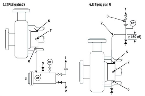
FIG. 6. API 682 seal Plan 75 and 76 configurations. Source: API. - The visual inspection of the seal auxiliary system at the plant showed that the seal chamber vent line was blinded. This means that the seal will not be properly vented, which can cause seal failures especially after pump priming. Therefore, the inboard and outboard seal vent lines must be connected to the closed drain system or the flare header to ensure venting of the stuffing box when needed. Further enhancement may be achieved if pressure indicators can be added at these two vent lines to show the stuffing box pressure. This will aid in troubleshooting future mechanical seal failures.
RECOMMENDATIONS AND ACTION PLAN
The required actions to resolve the fundamental pump and seal system design deficiencies include:
- Remove the pump suction strainers. If a large foreign object or high quantity of sludge is expected, the plant may keep a large-opening strainer (> 0.25 in.) to ensure the strainer will be cleaned when the differential pressure reaches 0.5 psi.
- If an increase in the current process flowrate is not expected, consideration should be given to re-rate the current pump for the actual operating conditions.
- Connect the inboard and outboard seal vent lines to the closed drain system or the flare header to ensure venting of the stuffing box when needed. A further enhancement may be achieved if pressure indicators can be added at the vent lines to show the stuffing box pressure.
Specific seal design recommendations. Recommended solutions for the seal design can be divided into two main options:
- Option 1: Keep the existing Arrangement 2 seal (dual-unpressurized seal) and attempt to resolve any deficiencies in it.
- Option 2: Use an Arrangement 3 seal (dual-pressurized seal) rather than the current Arrangement 2 seal, as recommended by API 682 for applications with a specific gravity < 0.5.
Option 1: Dual-unpressurized seal (Arrangement 2). To enhance the seal performance, remove the restriction caused by one of the two seal API Plan 21 orifices. This can be done by opening one orifice to full bore size (i.e., no flow restriction)—as indicated in FIG. 5—to avoid piping modifications that may be needed if the orifices were removed completely.
If significant contamination is observed or expected, consider adding a filter to API Plan 21. Re-install the flush line temperature measurement downstream of the API Plan 21 cooler. If corrosion pitting is still observed for future seals, verify the cause of the pitting and upgrade the seal material, as needed. Consider changing seal manufacturers to other seal vendors if issues are not fully resolved. In such cases, ensure the new seal is selected based on actual site operating conditions and request that the seal vendor provide its experience list for seals in similar operating conditions with satisfactory performance (i.e., at least 3 yr of MTBF).
Option 2: Dual-pressurized seal (Arrangement 3). As stated previously, low specific gravity liquids are difficult to seal. Therefore, API 682 recommends arrangement 3 seals for liquids < 0.5 specific gravity. This can be a very viable option, particularly if the seal material is upgraded from 316SS to duplex or super duplex.
The recommended seal plan for such a case will be API Plan 53B. The main benefit for an Arrangement 3 seal is that it relies on the barrier liquid to lubricate the seal faces. In such a case, a high-quality barrier liquid can be used to ensure high seal reliability. GP
WESAM KHALAF ALLAH works within the Consulting Services Department for Saudi Aramco.


Comments