
The best ways to deal with heavy hydrocarbons, oxygen and helium in LNG plant feed gas
Natural gas is one of the world’s most important sources of energy. Where natural gas pipelines are infeasible or do not exist, LNG is a way to move natural gas from producing regions to demand markets. Several recent LNG projects are based on pipeline gas (lean feed gas), which contains higher methane, with low natural gas liquid (C2–C5) and lower C5+ heavy hydrocarbon content than typical conventional natural gas. It is very challenging to remove a small amount of impurities to ensure a stable and efficient operation.
Where does heavy hydrocarbon come from? Natural gas is available from conventional natural gas reservoirs and unconventional gas, such as shale gas, tight gas and coalbed methane. There are two primary sources for feed gas to an LNG plant: dedicated natural gas reservoirs and pipeline gas from mixed sources.
Hydrocarbon streams produced at the wellhead are composed of gas, liquid hydrocarbons and, sometimes, free water. The liquids from the gas phase are separated by passing the well stream through an oil-gas or oil-gas-water separator.
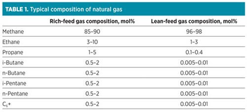
For pipeline gas, the removal of C2+ heavy hydrocarbon components from natural gas is required to avoid the unsafe formation of a liquid phase during transportation. Therefore, pipeline gas is usually lean. However, a small amount of aromatics—such as benzene, toluene and xylene (BTX)—and C5+ often remain in the gas. The typical composition of natural gas is detailed in TABLE 1.
 |
What are the possible effects of trace amounts of heavy hydrocarbons in the lean natural gas feed of an LNG plant? The presence of heavy hydrocarbons in natural gas can result in a freezing out of the gas at liquefaction temperature, causing a significant adverse performance impact. Even trace concentrations of heavy hydrocarbons and aromatics can cause precipitation of solids (freezing) and fouling of the main liquefaction heat exchangers. When the freeze-out of heavy hydrocarbons occurs inside the exchange cores, pressure drop increases across the cores. This leads to flow maldistribution in the cores, which results in thermal stresses and core leaks.
When the core pressure drop reaches a high limit, the LNG train has to be shut down to defrost the exchangers and remove the heavy hydrocarbon deposits. Defrosting results in production loss and increases process risks such as equipment failure.
Hydrocarbons can also create operational and performance problems in the amine unit or the reinjection system.
What can be done to mitigate the effects of heavy hydrocarbons? This trace of heavy components must be removed prior to liquefaction. A few conventional separation schemes are available that use a scrub column and a liquids extraction unit that is integrated with the liquefaction process. These conventional technologies are often not feasible due to the low amount of heavy components. In addition, front-end natural gas liquids recovery processes may be feasible; however, an increase in capital and operational expenditures is associated with these configurations for the removal of only a small content of aromatics and heavy hydrocarbons.
A proprietary adsorption technologya is one of the most feasible solutions for lean gas natural gas processing. The adsorption technology is specifically designed for the removal of aromatic hydrocarbons (BTX) and heavy hydrocarbons from lean gas feeds in LNG pre-treatments (FIG. 1). This advanced technology combines both unit functionalities into one system by utilizing a multi-material approach to achieve heavy hydrocarbon and water removal to the required cryogenic specifications. This approach provides a 30% increase in capacity for BTX components, allowing for the effective removal of BTX to less than 1 ppm without compromising unit efficiency.
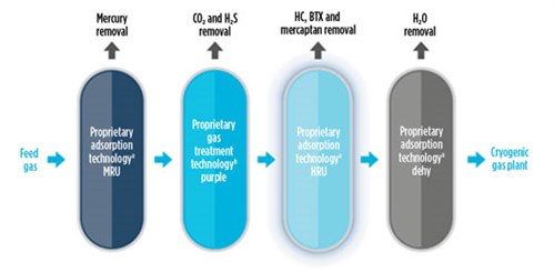 |
| FIG. 1. The proprietary adsorption technologya is specifically designed for the removal of aromatic hydrocarbons (such as BTX) and heavy hydrocarbons from lean gas feeds in LNG pre-treatments. |
Natural gas extracted from conventional natural gas and/or oil fields does not generally contain oxygen (O2). However, it is common to find certain high O2 concentrations in U.S. natural gas pipelines (greater than 10 ppmv) in some sampling analyses (where pipeline specifications are normally set at 10 ppmv). Usually, the presence of O2 in natural gas sampling measurements is due to poor sampling procedures or to misread gas chromatograph results (it is not uncommon to confuse argon with O2 when reading gas chromatograph results). It is also proven that some samples show much greater than 20 ppmv O2 content, and most pre-treatment licensors can design systems to handle up to 20 ppmv of O2. In some cases, the O2 content may show values of 100 ppmv.
Helium is a very valuable gas in the industry. It is extracted from natural gas, which typically contains 1 vol%–8 vol% helium. While O2 is a problem, helium might be a blessing. The following will analyze the challenges with O2.
Where does that O2 come from? Natural gas produced in conventional wells (either gas or oil) does not contain O2, which can be found in gas lines fed by landfills, vacuum oil recovery systems, coal mine methane (CMM) or other low-pressure gas collection systems—all of which can contain several percent of O2. Other sources of O2 can be related to air ingress from field compressors in natural gas extraction systems (i.e., packing on low-pressure well compressors) or through ingress from upstream oil and/or gas production facilities (i.e., through tank vacuum breakers and inadequate control in vapor recovery units of storage tanks or O2 rejection from helium recovery units) failure or lack of tank blanketing systems.
What can O2 in natural gas feed do in an LNG plant? Even at low levels, the presence of O2 in natural gas can result in the corrosion of pipes in LNG plants, which can cause safety hazards due to catastrophic gas leaks. O2 can potentially impact the acid gas removal unit (AGRU) or the molecular sieve dehydration system. In the AGRU, O2 can lead to a continuous formation of contaminants (bicine) by the degradation of the amine in methyl diethanolamine systems.
The reaction of O2 with amines leads to the formation of different acids (i.e., formic, glycolic and oxalic), in which ions will form salts stable to heat. These salts increase the risk of foaming and fouling in the amine system, causing change in the amine strength and reducing the treating capacity of the amine system. Therefore, the AGRU will require more actions to maintain the amine quality.
In the dehydration unit, O2 in the regeneration gas will result in the formation of water due to the oxidation of the light hydrocarbons during the regeneration heating stage. When present in excess of design limits, O2 can cause problems in the dehydration unit because of the high temperature during the regeneration step. At the regeneration temperature, O2 can produce an oxidation reaction that would generate water. If the natural gas also contains sulfur, the O2 present in the regeneration gas stream will lead to the formation of sulfur dioxide (SO2). Adding the presence of water will lead to hydrogen sulfide (H2S) and sulfur. Sulfur can cause adsorbent deactivation and corrosion of materials in cooler parts of the regeneration section, as well as channeling and high pressure drop in the molecular sieves.
What can be done to mitigate the effects of O2? The simple answer would be to remove O2 from the feed gas (FIG. 2). In this sense, not many commercially proven O2 removal systems exist in LNG plants. O2 removal systems for LNG applications are based on catalytic reactions and solid scavengers (although there are not many references for the latter). A continuous adsorption-based process—using copper as the adsorber in at least two columns—could be used, but a reducing agent (hydrogen) would also be needed, which is very costly and not available in LNG plants. Therefore, we are left with systems based on catalytic reactions. For this option, the catalytic combustion of O2 can be used to remove O2 from natural gas. The combustion of O2 in natural gas yields water and carbon dioxide (CO2). Produced CO2 will be removed in the downstream amine unit. Based on 50 ppmv of O2 in the feed gas, there will be less than 50 ppmv of CO2 in the feed to the AGRU, which will have minimal impact on AGRU operations.
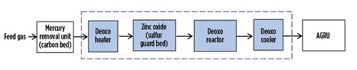 |
| FIG. 2. A typical feed gas O2 removal unit. |
These systems consist of a catalytic reactor with enough catalyst to remove the O2 and produce CO2 and water. The water could ultimately be separated in a separator or coalescer. However, it does not seem to be a feasible solution in LNG plants that might expect O2 to be present in the feed gas.
Membrane technologies, like the ones used to remove CO2 from natural gas, have been considered in some projects. However, there are no commercial membrane materials with proven results for the removal of O2 from the natural gas.
Operational procedures in the LNG plant can be implemented to deal with O2 contamination. These include the following:
- Consider the substitution of amine in the AGRU. The O2 reacts with amines to form bicine and heat stable salts (HSS). Mitigation would occur by removing amine, using a portable reclaiming facility in the AGRU. The reclamation can be achieved with a mobile or permanent unit. When properly implemented, ion exchange technology has proven successful in removing HSS and bicine.
- In this process (FIG. 3), the lean amine solution is pumped into the ion exchange unit. The ion exchange resin removes the HSS, and the purified amine solution is returned to the amine circuit. After several minutes of operation, the system rinses the amine, using demineralized water from the resin, and a regeneration sequence takes place.
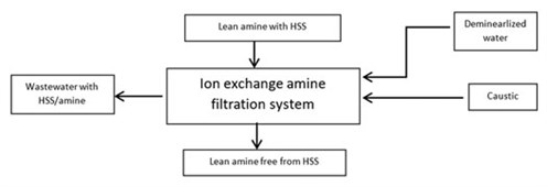
FIG. 3. Ion exchange filtration. - To avoid possible operational problems in the dehydration unit, some dehydration unit licensors recommend staging the heating procedure to minimize the time in which the O2 would be exposed to the high regeneration temperature. The idea is that, since most of the regeneration step occurs at mid-temperatures (around 340°F), the regeneration cycle is maintained at the same temperature. The final step is to heat the oxygen to high regeneration temperatures (445°F).
A combination of these two operational modes could handle up to 50 ppmv of O2 content in the composition of the feed gas.
Should the O2 content exceed 50 ppmv, the only feasible permanent solution is the installation of a closed-loop regeneration system in the dehydration unit. This solution falls within the realm of licensed designs. In this manner, there is no impact to the dehydration unit, and the regeneration operation would be under normal conditions (i.e., no high O2 present). These types of installations would increase the regeneration needed for each dehydration bed; however, if the standby time is large enough, the overall dehydration-regeneration sequence would not be affected.
Helium recovery. Should the natural gas be rich in helium, the helium can be recovered in an integrated helium-nitrogen rejection unit in the LNG plant. However, in cases where the helium concentration is low, it is not economically feasible to extract it out of the natural gas stream.
How can the extraction of low-concentration helium be economical in LNG plants? Boil-off gas (BOG) from LNG storage tanks is usually used as fuel gas for gas turbines in liquefaction plants (or for thermal oxidizers in plants that have electric motors as drivers). Besides methane, BOG also contains nitrogen, hydrogen, helium and some other heavier hydrocarbons. Depending on the case, a helium extraction unit can be installed in the BOG stream upstream of the BOG compressor; however, the purity requirements to export helium (> 95%) might require installing a hydrogen removal unit downstream of the helium extraction unit.
At present, there are several solutions to extract helium from natural gas. These solutions include membrane separation, pressure swing adsorption (PSA) and cryogenic processes. The latter seem to be the most economical solutions for this type of plant.
BOG components have different boiling temperatures; therefore, processes based on condensation and/or distillation seem to be adequate for this purpose. Generally, and from the perspective of producing helium with the required purity, high condensation pressures would be required to achieve such purity. In distillation processes, higher pressures lead to higher power consumption due to higher condensation duties.
A combination of both condensation and distillation is the most adequate solution to optimize the feed stream temperature and pressure of the cryogenic distillation column. The possible integration of a device to cool down the helium to condense the BOG to a lower temperature would provide favorable stripping through the condensation separation process at a relatively lower pressure. The low operating pressure would decrease the condenser duty and, thus, the power consumption of the system.
Takeaways. Even small amounts of heavy hydrocarbons in lean gas can be of critical concern for stable and efficient operations. While conventional technologies for lean natural gas processing are often infeasible due to the low amount of heavy components, the new adsorbent technologya is one of the most feasible solutions for lean natural gas processing.
The presence of O2 in natural gas is problematic above a certain content; however, before considering any O2 removal installation or change in operational procedures, it is imperative to confirm the existence of this gas within the natural gas stream.
While the extraction of helium also adds complexity to LNG process facilities, the payback period of such installations is very short. The overall profit of the LNG plant will be increased due to additional revenues generated from exporting extracted helium. Taking this into account, helium is a prize that can be well worth the extra effort and investment to obtain. GP
NOTE
a BASF’s Durasorb Cryo-HRU technology
b BASF’s OASE technology
 |
MADANMOHAN PATEL is a Registered Professional Engineer in Texas and Louisiana, with more than 17 yr of chemical and process engineering experience in the LNG, petrochemical, chemical, oil and gas, and power industries. His experience is in supporting plant operational needs and in providing process expertise to troubleshoot and mitigate different plant issues. Mr. Patel earned an MS degree in chemical engineering from Texas A&M University.


Comments