
Innovative technology for re-liquefying evaporated LNG to meet net-zero emissions targets
In the current era, environmental challenges do not exist in isolation. The protection of the environment is one of the greatest challenges facing the world.
Many industries are swiftly moving toward the green environment, and many companies are adopting more stringent environmental regulations that require the provision for a vapor control system to reduce the emissions of volatile organic compounds (VOCs). These investments are to ensure improvements in air quality, resulting in a healthier environment and improving the health and well-being of its inhabitants.
Vapor recovery for LNG. In countries like Australia, vapor recovery has become mandatory in major urban areas. One technology that has evolved is re-liquefaction of evaporated LNG—boil-off gas (BOG)—on LNG carriers. The BOG released from LNG storage vessels on carriers can be used to power the steam turbines to run the ships, all the while reducing greenhouse gas (GHG) emissions. Advancements in turbo-expander technologies have led to the development of new re-liquefaction systems.
LNG usually comprises methane, ethane, propane, butane and nitrogen. LNG is sold on an energy basis—therefore, the composition of the product is of great importance. Nitrogen is normally removed from the natural gas stream through a nitrogen rejection unit to increase LNG’s energy value. The energy value of LNG is measured based on the higher heating value (HHV), which is the amount of heat obtained by the complete combustion of a unit quantity of a material.
LNG is stored at approximately –163°C in tanks close to atmospheric pressure. The pressure in the tanks is normally less than 7 psig. LNG cryogenic storage tanks are equipped with extremely efficient insulation; however, heat is still transmitted due to the surrounding atmosphere. For the LNG to stay liquefied, it must stay at or near constant temperature, which can be achieved if the tank is held at a constant pressure.
To remain at a constant pressure, the LNG vapor boil-off is allowed to leave the tank, which will keep the pressure constant. BOG from the cryogenic tank is of high value; therefore, it is compressed and used as a fuel gas (not flared).
BOG may also be produced when LNG is pumped into LNG carriers. Due to the temperature of the empty tanks, BOG forms quickly. The rate that the BOG is produced begins to slow down quite substantially as the LNG and the tank temperatures reach equilibrium. BOG can be converted to a fuel source, or it can be re-liquefied in the stream and exported as LNG. Re-liquefaction systems can be optimized based on the following:
- Arrangements of the turbo expander
- The pressure of the BOG liquefaction system
- The refrigerant selection.
With the optimization of the turbo-expander arrangements (the refrigerant selection and the BOG feed pressure), energy savings of approximately 30% can be achieved.
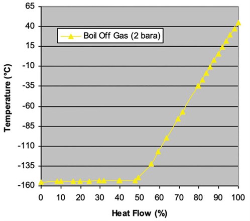
Nitrogen liquefaction systems. There is a constraint on refrigerant at a pressure of 2 bara due to the necessity of latent heat at –155°C. Nitrogen is the only refrigerant that can efficiently liquefy the BOG at 2 bara.
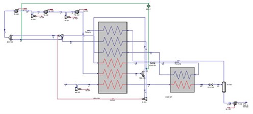
FIG. 1 is a generic process flow diagram required for the liquefaction of BOG at 2 bara. The flow through the Joule-Thomson (JT) valve provides the latent heat required to liquefy the process fluid. The purpose of the JT valve is to provide liquid nitrogen expansion, which provides the latent heat required at the cold end of the system. The discharge pressure must be controlled to have an efficient system. When nitrogen is used as a refrigerant, the discharge pressure from the JT valve is acceptable. Because of the boiling temperatures of the components, a methane refrigerant has a discharge pressure near atmospheric pressure.
 |
| FIG. 1. Process flow diagram required for BOG liquefaction at 2 bara. |
The LNG is cooled using liquid nitrogen, which is cooled by the nitrogen in the cold and warm turbo expanders. FIG. 1 shows the use of a JT valve for latent heat cooling and a turbo expander in re-compressor mode to provide sensible heat for warm-end cooling. The following are the main points of this study (FIGS. 2 and 3):
 |
| FIG. 2. LNG heating curve. |
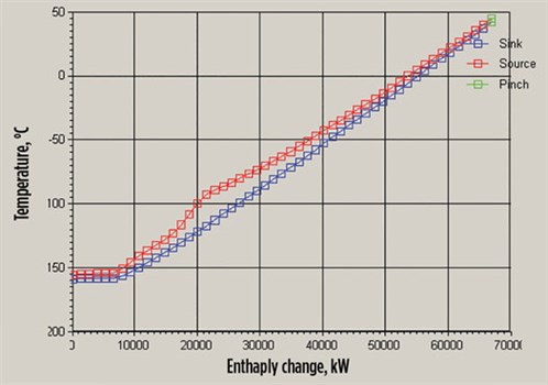 |
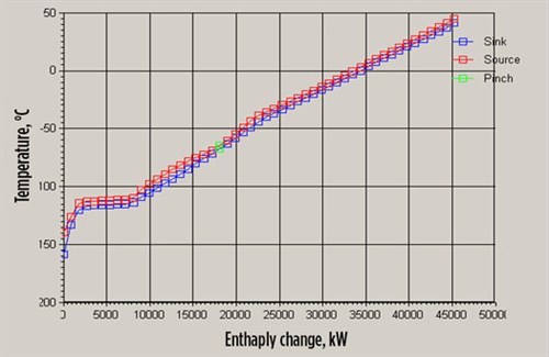
| FIG. 3. Enthalpy change-temperature. |
- Sufficient heat is between ambient temperature and –155°C.
- Nitrogen refrigerant can provide latent heat at –155°C at realistic operating conditions (methane at 160 kPaA).
- The nitrogen and carbon system is more efficient.
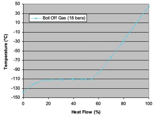
With a combined refrigerant case, a turbo-expander loop will cool, using a nitrogen feed, and a second turbo-expander loop will cool the warm end with a methane feed. The intermediary section—which requires latent heat—will be cooled with the use of liquid methane. The methane system at the cold end will use latent heat to provide the required cooling. The limitation is that methane will begin to condense in the temperature range between –110°C and –143°C (FIGS. 4 and 5). The details of this case include:
 |
| FIG. 4. LNG heating curve for combined refrigerant case. |
 |
| FIG. 5. Enthalpy change-temperature for combined refrigerant case. |
- The requirement of latent heat is –110°C.
- Nitrogen refrigerant can provide sensible cooling at –155°C.
- Latent heat is provided with methane at –110°C within realistic operating conditions.
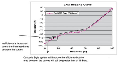
The turbo-expander system is only able to follow a straight path; therefore, there will be areas of inefficiency at the significant points of curvature. Looking at systems at 18 bara and 2 bara, there is no real curvature. The changes in the curves are sharp, and this can be modeled using a turbo-expander cycle. At 50 bara, a mixed refrigerant could be used to follow the curves more efficiently (FIG. 6). The varying composition of methane, ethane and nitrogen means that the evaporation of the refrigerant will occur over a larger range of temperatures. The accurate selection of the mixed-refrigerant composition is critical to follow the cold end of the LNG heating curve. The problem with this system is that methane will still condense at low-end temperatures. The result will be a larger gap of inefficiency, which is significant. The process flow diagram and enthalpy change are shown in FIGS. 7 and 8.
 |
| FIG. 6. LNG heating curve of turbo-expander system. |
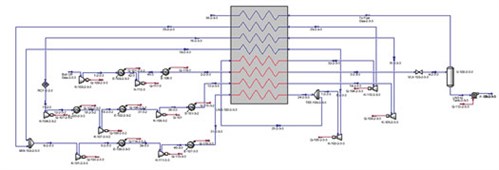 |
| FIG. 7. Process flow diagram of turbo-expander system case. |
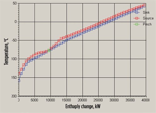 |
| FIG. 8. Enthalpy change-temperature of turbo-expander system case. |
Mixed-refrigerant liquefaction systems. The LNG heating curves play an important role in the selection of the refrigerant. Mixed refrigerant would be unable to achieve cooling along the flat sections of the heating curves. When the BOG is at 50 bara, there is more curvature in the heating curve. This means that the process fluid is condensing through a wider range. For this reason, a mixed refrigerant is suitable, since the components will also condense at different temperatures. A mix of the three components (methane, ethane and nitrogen) will result in a curve that will justifiably provide cooling at the cold end of the system.
The warm end of the system can be cooled with the use of heat. Therefore, the use of turbo expanders is appropriate. The turbo-expander cycle can use nitrogen, methane or mixed refrigerant as a refrigerant. As proved in the previous models, methane is a more effective refrigerant due to its molar enthalpy. In addition, ethane should be a better refrigerant than methane; however, its range of operation is limited.
The mixed refrigerant will be more efficient at the cold end due to the latent heat of vaporization that it possesses. If mixed refrigerant is only being used at the cold end, heavier hydrocarbons (such as propane and pentane) should not be used.
Warm-end cooling can be achieved by using heat provided by expansion. Mixed refrigerant is more efficient than nitrogen at the warm end, as it possesses a higher molar heat capacity. Therefore, mixed refrigerant is normally used in the warmest turbo expander to provide the greatest efficiency within the operating limitations of the expanders.
With the optimization of the turboexpander arrangements, the refrigerant selection and the BOG feed pressure, energy savings of approximately 27% can be achieved.
The system’s efficiency improves with increasing the BOG feed pressure. When the BOG feed pressure is increased, the heating curve becomes more curved. Condensation does not take place over a limited area, but rather across a larger area.
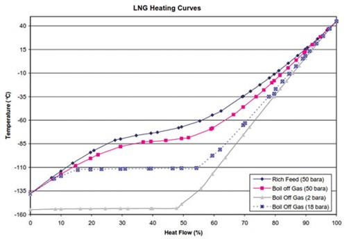
The BOG will liquefy more efficiently at a higher feed pressure. This is clearly presented by the respective LNG heating curves in FIG. 9. As the feed pressure of the BOG is increased, the curvature in the LNG heating curve begins to increase. The heating curves also show the required cooling.
 |
| FIG. 9. BOG will liquefy more efficiently as a higher feed pressure. |
This means that methane is more efficient than nitrogen due to the molar heat capacity it possesses. This was a significant advantage, and methane was used for all warm-end refrigeration. The challenge with methane was its ability to provide sensible heat at cold temperatures below –110°C. Due to methane having a warmer boiling point than nitrogen, it was unable to effectively provide cooling below these temperatures, using a turbo-expander cycle. At 18 bara, the evaporation of methane to provide cooling was still more effective than the combined nitrogen and methane system. At 50 bara, methane was inefficient due to its inability to follow the curve at the cold end. In this case, it was advantageous to have combined nitrogen and methane systems.
Further advantages included using ethane as a refrigerant, which has an even higher molar heat capacity than methane. The use of a mixed refrigerant with ethane then became quite attractive. Ethane has a higher boiling point and begins to condense at warmer temperatures. This restricts its use in turbo expanders, where the discharge stream must have less than 10% liquid flow. In the most efficient modeled system, the mixed refrigerant only passes through the warmest turbo expander to produce no liquid on the outlet of the expander. This still provides a significant energy savings of approximately 3% vs. methane being passed through the expander.
Therefore, methane was a more effective refrigerant than nitrogen since methane has a higher molar heat capacity. This makes the methane system more efficient than the nitrogen system. The same was found with the mixed refrigerant, which condensed at a higher temperature due to the ethane content. The mixed refrigerant has an even higher molar heat capacity than the methane due to the presence of ethane. This justified why the mixed refrigerant system—with mixed refrigerant flowing through the warmest expander—was the most efficient system.
A large amount of energy could be efficiently recovered, and maximum efficiency of the whole process system could be achieved by applying the best engineering approach. Simultaneously, it would also contribute to reducing the exposure of GHG and to improving the air quality, resulting in advancements toward achieving net-zero emissions targets. GP
 |
ADIL RAZA is a Process Engineering Head for KBR-AMCDE in Al-Khobar, Saudi Arabia. As a professional chartered chemical engineer, he has extensive experience in the design of offshore/onshore oil and gas processing facilities. Mr. Raza has carried out many conceptual, FEED EPCC design projects—he handled basic and detailed engineering design and conducted engineering and safety studies. He has worked for various renowned operating and consulting companies on a global basis.


Comments