
Customize selection of hydrocarbon dewpoint control technology
The purpose of a hydrocarbon dewpoint control unit is to remove hydrocarbon liquids (NGL) from natural gas so that the hydrocarbon dewpoint specifications of the sales gas (local requirement is 0°C at any pressure) can be met. A challenge for plant designers is to choose the most suitable technology for hydrocarbon dewpoint control. The technology must be technically and economically capable of continuous, trouble-free operation, with optimum outcome. It must have the flexibility to adjust the water and hydrocarbon dewpoints of the sales gas to the required pipeline specification on maximum and turndown conditions without affecting the performance of the plant, even in the worst-case scenario.
The selection of appropriate technology for hydrocarbon dewpoint reduction must consider several factors. It is imperative for the plant designer to understand the key factors that contribute to the choice of the best technology for the plant, particularly at the conceptual design stage.
Three hydrocarbon dewpoint control technologies are commonly used: Joule-Thomson (JT) valve technology, turboexpander technology and mechanical refrigeration technology. Significant research is available on each type of technology independently, but a comparative analysis must be performed for each technology in relation to the others based on key impacting factors, as the optimum performance of the plant relies on the proper selection of technology.
This comparative process analysis will ascertain the application and pros and cons of each dewpoint control process and technology with the objective of selecting the most suitable process for the specified gas treatment plant. The ultimate selection is based on the financial viability of the process schemes and the technical comparison where the impact of the contributing factors is identified.
Process simulations are prepared for all three technologies with results to show the optimum scheme, along with other contributing factors in the selection of technology. The key contributing factors considered for comparison are complexity of operation, turndown, reliability and availability, pressure drop, sales gas specifications and others.
Mechanical refrigeration technology. In the mechanical refrigeration scheme, gas from the upstream processing unit is routed to the gas/gas heat exchanger that provides a means of heat exchange between the raw gas and the low-temperature separator (LTS) gas; therefore, the precooling of the raw gas is achieved in this heat exchanger. As the temperature drops, some condensation occurs downstream of the gas/gas exchanger. The gas is then passed through the chiller to further reduce its temperature, which promotes additional condensation.
The combined stream [gas, condensed hydrocarbon and the ethylene glycol (EG)/methanol solution] is then introduced in the LTS to segregate the gas, liquid hydrocarbons and the EG/methanol solution. After the separation of NGL, gas from the LTS will have dewpoint, as per pipeline specifications. This dewpoint-specified gas is then routed through the gas/gas heat exchanger, as previously discussed, to exchange heat with the raw gas and exit as sales gas.
Cooling of the raw gas in the chiller is achieved by using propane as refrigerant for heat exchange. Propane gains energy and vaporizes in the chiller after heat exchange. Vaporized gas is routed to the refrigeration unit, where it is condensed after being recompressed in the refrigerant compressor and routed to the refrigerant accumulator. Propane fill/makeup in the refrigerant loop is carried out at the refrigerant accumulator. Compressed propane is finally cooled/chilled at the required temperature by pressure letdown across the valve. Chilled propane is then introduced back into the chiller for heat exchange.
NGL from the LTS is first passed through the multipass exchanger to raise its temperature above the hydrate formation temperature before being routed to NGL storage.
Glycol solution (EG) or methanol is injected in raw gas at the inlet of the gas/gas exchanger to avoid possible hydrate formation at low operating temperature. Rich EG/methanol solution collected from the LTS is routed to the glycol/methanol regeneration system, which, after processing, recycles back lean EG/methanol solution to the dewpoint reduction unit (FIG. 1).
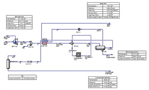 |
| FIG. 1. Process scheme for mechanical refrigeration technology. |
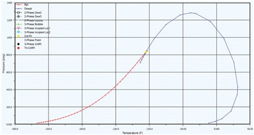
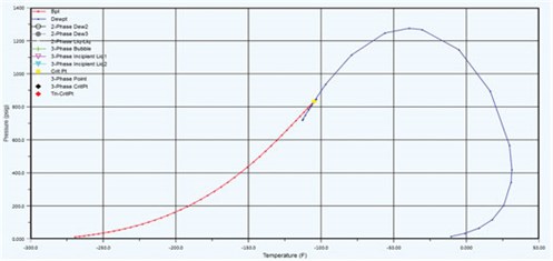
Phase envelope. Proprietary simulation steady-state softwarea is utilized to simulate the hydrocarbon dewpoint control unit. FIG. 2 shows the phase envelope for lean sales gas after processing through a mechanical refrigeration-based hydrocarbon dewpoint control unit.
 |
| FIG. 2. Phase envelope for lean sales gas after processing through a mechanical refrigeration-based hydrocarbon dewpoint control unit. |
Application pros and cons. The application of the mechanical refrigeration processing route has a number of benefits and challenges:
- Although this technology is conventional and can produce the required sales gas hydrocarbon dewpoint specification, it is not suitable at higher operating pressures, as more cooling is required at high operating pressures to extract the same amount of heavier component as compared to relatively low or moderate pressures
- If adequate pressures are not available at the feed of the hydrocarbon dewpoint control unit, then mechanical refrigeration can be used for the elimination of hydrocarbons from raw gas
- The availability and reliability of the unit is lower as compared to other units because of rotating equipment like the refrigerant compressor and the refrigerant cooler (air cooler); however, this can be mitigated with scheduled maintenance and proper monitoring
- Pressure drop in the gas path of the chiller and gas/gas exchanger is low; therefore, sales gas compression is not required
- A refrigerant is required for first fill and makeup due to losses from the system, which adds to OPEX; the costs of other components of the refrigeration unit add to CAPEX.
Turboexpander technology. A turboexpander scheme is used where a substantial amount of C3+ components are available in the feed gas stream to be extracted. In the turboexpander scheme, gas from the upstream processing unit is routed to the gas/gas heat exchanger, which provides a means of heat exchange between the raw gas and the LTS gas; therefore, the precooling of the raw gas is achieved in this heat exchanger.
As the temperature drops, some condensation occurs downstream of the gas/gas exchanger, and the combined stream (gas, condensed hydrocarbon and the EG/methanol solution) is then introduced in the cold separator to segregate the gas, liquid hydrocarbons and the EG/methanol solution. Outlet gas from the cold separator is then isentropically expanded in the expander section of the turboexpander.
At the suction nozzle of the turboexpander, the ethylene glycol/methanol solution is injected as a fine mist to avoid possible hydrate formation in the expander and at the downstream system. The decrease in temperature due to expansion promotes further condensation. The combined stream (gas, condensed hydrocarbon and the ethylene glycol/methanol solution) is then introduced in the LTS to segregate gas, liquid hydrocarbons and the ethylene glycol solution. After separation of NGL, gas from the LTS will have dewpoint as per pipeline specifications; however, it still requires compression. This dewpoint-specified gas is then routed through the gas/gas heat exchanger to exchange heat with raw gas, followed by compression through the turboexpander-driven sales gas compressor up to the required sales gas pressure.
NGL from the LTS and cold separator is first passed through the multipass exchanger to raise its temperature above the hydrate formation temperature before being routed to NGL storage.
EG or methanol is injected in the raw gas at the inlet of the gas/gas exchanger to avoid possible hydrate formation at low operating temperature. Rich EG/methanol solution collected from the LTS and the cold separator is routed to the glycol/methanol regeneration system, which, after processing, recycles back lean ethylene glycol solution to the dewpoint reduction unit (FIG. 3).
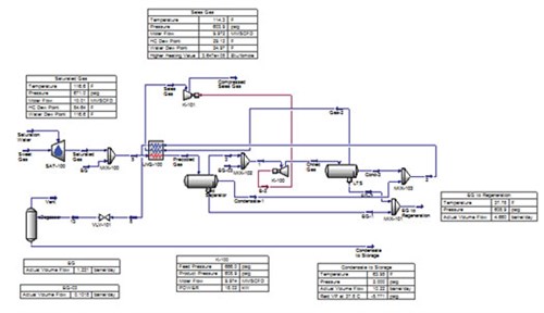 |
| FIG. 3. Process scheme for turboexpander technology. |
Phase envelope. Proprietary simulation steady-state softwarea is utilized to simulate the hydrocarbon dewpoint control unit. FIG. 4 shows the phase envelope for lean sales gas after processing through the turboexpander-based hydrocarbon dewpoint control unit.
 |
| FIG. 4. Phase envelope for lean sales gas after processing through the turboexpander-based hydrocarbon dewpoint control unit. |
Application pros and cons. The application of the turboexpander technology processing route has a number of benefits and challenges:
- Turboexpander-based dewpoint reduction technology is mostly used in cryogenic process—i.e., where LPG or high recoveries of C2 and C3+ components are required
- The major benefit of the turboexpander scheme is the utilization of expansion energy for the recompression of gas; therefore, the energy requirement for the external sales gas compressor is reduced
- The existence of complex rotating equipment (expander and compressor) demands maintenance and operation expertise, which impacts the availability and reliability of the plant
- Being complex and high in capital cost, turboexpander technology is used for high and constant feed flowrates, and it is difficult to control and turndown
- When used for cryogenic process, almost fully dehydrated gas is required by turboexpander technology to prevent hydrate formation, as LTS temperature will drop in cryogenic range; therefore, a solid-bed system or a silica gel-based dehydration unit is required instead of a glycol dehydration unit to dehydrate the gas completely before processing it through a turboexpander
- With the use of this technology, very low hydrocarbon dewpoint can be achieved.
JT valve technology. In principle, JT valve technology utilizes the Joule-Thomson effect to achieve the required cooling for separation of heavier hydrocarbons, thereby attaining dewpoint reduction in gas at the outlet of the unit. Gaseous hydrocarbons are cooled by throttling its flow through the JT valve, initiating rapid expansion. This phenomenon is known as the Joules Thomson effect. The quantity of NGLs recovered is a function of the gas composition, pressure, temperature and pressure drop across the JT valve.
Gas from upstream of the processing unit is routed to a gas/gas heat exchanger, which provides a means of heat exchange between the raw gas and LTS gas; therefore, precooling of the raw gas is achieved in the heat exchanger. As the temperature drops, some condensation occurs downstream of the gas/ gas exchanger.
Outlet gas from the cold separator is then adiabatically expanded through a pressure control valve (JT valve).
The decrease in temperature due to expansion promotes further condensation. The combined stream (gas, condensed hydrocarbon and the EG/methanol solution) is then introduced in the LTS to segregate gas, liquid hydrocarbons and the ethylene glycol solution.
After the separation of NGL, gas from the LTS will have dewpoint as per pipeline specifications; however, it still requires compression. This dewpoint-specified gas is then routed through the gas/gas heat exchanger to exchange heat with raw gas, followed by compression through the sales gas compressor up to the required sales gas pressure.
EG or methanol is injected in raw gas at the inlet of the gas/gas exchanger to avoid possible hydrate formation at low operating temperature. Rich EG/methanol solution collected from the LTS is routed to the glycol/methanol regeneration system, which, after processing, recycles back lean ethylene glycol solution to the dewpoint reduction unit.
Condensate (NGL) from the LTS is first passed through the multipass exchanger to raise its temperature above the hydrate formation temperature before being routed to NGL storage (FIG. 5).
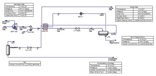 |
| FIG. 5. Process scheme for JT valve technology. |
Phase envelope. Proprietary simulation steady-state softwarea is utilized to simulate the hydrocarbon dewpoint control unit. FIG. 6 reveals the phase envelope for lean sales gas after processing through a JT valve-based hydrocarbon dewpoint control unit.
 |
| FIG. 6. Phase envelope for lean sales gas after processing through a JT valve-based hydrocarbon dewpoint control unit |
Application pros and cons. The application of the JT valve technology processing route has a number of benefits and challenges:
- For small, high-pressure feed gas streams, JT valve is the technology of choice to yield on-spec hydrocarbon dewpoint sales gas
- High turndown ratio can be achieved with this technology
- It is a self-refrigeration process; no external cooling medium is required
- It requires high pressure drop, and pressure that is dropped across the JT valve cannot be recovered; energy is required to recompress the on-spec dewpoint gas as per sales gas injection pressure
- JT valve technology has the capability to operate on high turndown, with ease of operation.
Technical comparison of technologies. Key technology features are compared in the following sections.
Operation. In the absence of complex rotating equipment like a turboexpander or a refrigeration compressor required for cooling, JT valve technology has a simple and flexible operation.
Turndown ratio. JT valve technology has the highest turndown ration among the proven technologies.
Turboexpander technology has the lowest turndown ratio among all the options, as a centrifugal compressor is an integral part of the turboexpander.
With the use of a screw compressor as part of the mechanical refrigeration unit, turndown almost equal to that of JT valve technology can be achieved.
Reliability and availability. JT valve technology has the highest reliability among all considered options, whereas turboexpander technology has the lowest reliability due to the number of rotating equipment.
Pressure drop. JT valve technology requires high pressure drop for cooling and requires the highest quantity of fuel gas for sales gas compression.
Mechanical refrigeration technology requires the lowest pressure drop and lowest quantity of fuel gas; however, this saving in energy is partially offset by running the refrigeration compressor.
Turboexpander technology requires a higher pressure drop for expansion than a mechanical refrigeration unit, but the expander and compressor partially compensate for this.
Recompression requirements. Recompression is required for JT valve technology, whereas other technologies do not require recompression, since their pressure letdown is low.
Feed gas requirements. Turboexpander technology can be used for high feed gas flowrates; however, other technologies can be used for a wide range of feed gas flowrates.
Sales gas specification. Sales gas specifications can be met through all of the compared hydrocarbon dewpoint technologies.
Recovery. Sales gas recovery with JT valve technology and NGL recovery with mechanical refrigeration technology are highest; however, simulation operating parameters used will have an effect on these recoveries.
Takeaway. The basis application for each type of hydrocarbon dewpoint technology should be considered against the specific requirement of the gas to be processed. The capital cost of each technology, which is not considered in this article, should also be taken into account along with the limitations and suitability of the technologies discussed in this article. The better the technology selection, the more optimum will be the results. GP
NOTES
a HYSYS
 |
ASAD ASHFAQ LODHI is a Process Engineer with Zishan Engineers Pvt. Ltd in Karachi, Pakistan. With 10 yr of professional experience in process engineering, particularly in the gas processing and refining sector, Mr. Lodhi has experience in FEED, detailed engineering and feasibility studies for various oil and gas processing plants and refineries. Prior to joining Zishan Engineers, he worked at Descon Engineering. He holds a BS degree in chemical engineering and an MS degree in project management, as well as a NEBOSH International General Certificate.


Comments