
Turbomachinery configuration for LNG project concept selection
Refrigerant compressors are the pumping heart of every LNG plant. These compressors are normally centrifugal and vary in size and configuration according to the context of the project. Steam turbines, gas turbines (heavy-duty or aeroderivative) and electric motors—or a combination of these three—are all possible options to drive the refrigerant compressors. It has been demonstrated that a single shaft can drive one, two or three compressor casings depending on the plant capacity, the liquefaction process technology used and the balancing needs of power. This is particularly interesting, as drivers with larger output power and efficiency can be considered.
This articlea elaborates on the selection of an optimum turbomachinery configuration from a technical perspective, building on technical experience attained through working on multiple concept and early front-end engineering design (FEED) studies for turbomachinery selection in LNG projects, some of which have been executed.
Mechanical drivers. Steam turbines were used as mechanical drivers for main refrigerant compressors in LNG plants until the 1980s, after which time gas turbines started to replace them. Electric motors have been used only occasionally in large-scale plants, but they have become popular at small- and mid-scale facilities.
Steam turbines can be custom-made to deliver any power level likely to be required by an LNG refrigerant compressor; however, the largest referenced electric motors are capped at around 75 MW. The largest gas turbine used to date is the heavy-duty Baker Hughes Frame-9, used across the LNG mega-trains at Qatargas’ Ras Laffan terminal. These turbines deliver 132 MW at International Organization for Standardization (ISO) conditions. They are catalogue machines available in discrete sizes, which makes the selection of an optimum gas turbine and shaftline configuration more challenging.
Compressor selection process. The production capacity of an LNG plant is directly linked to the power available from the refrigeration machinery. Consequently, the selection of the driver and the arrangement of the compressors is performed very early in a project, no later than at the early FEED phase. The final selection is made by the owner-operator based on engineering studies performed with the assistance of a specialized consultant (backed by a team of process and rotating equipment engineers) and in collaboration with the liquefaction process licensor. The overall selection study, all the way up to the recommendation to the owner, is supervised and led by the project management team.
At the beginning of a project, awareness on the general guidelines, characteristics and key criteria for the selection process should be determined with the owner. For example, the standardization of the gas turbine fleet could be an advantage where spare parts interchangeability and familiarity of operators and maintenance personnel with a specific gas turbine model are beneficial to operations.
Commercial relations should also be considered—for example, in a case where the owner favors one supplier with existing services agreement or, on the contrary, where the owner prefers to avoid a gas turbine supplier with limited service facilities in the country where the gas turbines will be installed.
Finally, some owners do not accept non-proven gas turbines that require qualification before the FEED or engineering, procurement and construction (EPC) phases; whereas other owners are willing to undertake a qualification process, including rigorous verification and extensive testing.
In these times of enhanced sensitivity to the carbon footprint of liquefaction facilities, electric motors as prime movers for the main refrigerant compressors are increasingly being taken into consideration. This is a departure from the situation to date, where electric motors have been the exception. For example, the promise of availability of a nearby source of power from the electric grid at a competitive price led the Snøhvit LNG plant in Norway to select a 65-MW electric motor for each compressor shaftline using the Linde Mixed Fluid Cascade (MFC) process. Also, because local regulations forbid fired equipment in an environmentally sensitive location, Freeport LNG on Quintana Island, Texas applied 75-MW variable-speed electric motors on each shaftline using the Air Products Propane Mixed Refrigerant (AP-C3MR) process.
In the coming years, it is anticipated that electric motor drives may become an attractive option due to the opportunity to reduce CO2 emissions by mixing in low-carbon sources of electricity.
Technical assessment. The first step in the technical assessment is to determine the required prime mover power for each shaftline depending on the LNG plant design and compressor configuration (see FIG. 1). This will depend on the targeted range of LNG plant production capacity in MMtpy, how many liquefaction trains are envisaged, which refrigeration process will be used and how many refrigeration cycles, and finally how many refrigeration compressor strings per train.
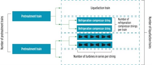 |
| FIG. 1. LNG plant screening of architecture. |
Several types of drivers can be considered to drive LNG compressors (gas turbines, steam turbines, motors), but once the choice is made it will usually apply to all the main refrigerant compressors for reasons of interchangeability, flexibility and maintainability. The selection should be reached in parallel to defining the compressor machinery arrangement to obtain the required balance of power and to select the standardized driver model for all shaftlines. Steam turbines and electric motors could be custom made to the required shaftline power; however, gas turbines come in discrete sizes and, therefore, the selection of optimum gas turbine depends on matching the available gas turbine models and versions.
At the early stages of concept definition, as many as 15 architectures or more can be screened and quantitatively ranked to support the owner’s selection when including the liquefaction process, machinery arrangement and other key selections. The criteria defined with the owner for the ranking and the selection are, at this stage, crucial to best match the owner’s objective and to ensure the success of the project.
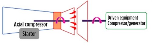
Gas turbine as a prime mover. Both heavy-duty gas turbines and aeroderivative gas turbines have been applied in LNG plants to drive main refrigerant compressors. The heavy-duty gas turbines have been adapted to mechanical drive from the versions built especially for the power generation industry and proven through decades of use. The power generation industry requires large power at a fixed speed, typically 3,000 rpm for a 50-Hz electric grid network and 3,600 rpm for a 60-Hz network. As a result of these constraints, large, heavy-duty, gas turbines have evolved (more than 500 MW in the largest sizes) with a single drive shaft. Startup torque for an offline generator is very low; however, the adaptation to mechanical drive in LNG plants implies the addition of large starter motors to overcome the compressor start from standstill torque.
Aeroderivative gas turbines were initially developed for aircraft engines, but in most cases have been first used in the power generation industry before being adopted for mechanical drive. Adaptation includes the addition of a free power turbine and the optimization of inspection and maintenance cycles that are obviously much longer for LNG trains than for commercial aircraft. The LM9000, which is now in the manufacturing stage for Novatek’s Arctic 2 project, is an aeroderivative gas turbine derived from the world’s most powerful civil aircraft engine and specifically developed for mechanical drive service in LNG.
Irrespective of the model, a referenced gas turbine must have field-proven design, meaning that it must have a proven and successful track record of performance in equivalent service, operating and process conditions. The gas turbine must have completed 25,000 hr for aeroderivative gas turbines/32,000 hr for heavy-duty gas turbines of continuous satisfactory operation in a continuous process plant without major problems or modifications.
Gas turbines with references coming only from the power generation industry cannot be considered as suitably referenced for mechanical drive application, as described. To qualify as a mechanical driver, they must be verified for the following:
- The rotor dynamics of the shaftline in the mechanical drive application must account for the gas density change that will occur during the operation of the coupled compressor, impacting the axial stability of the shaftline.
- The much higher startup torque for the mechanical drive should, if possible, allow startup from settle-out pressure to avoid flaring.
- In high-power gas turbines, the coupling and/or gearbox might not be referenced considering that the service factor will be higher in the mechanical drive than in power generation applications.
Once the required gas turbine site output power is estimated, then the ISO power can be determined by considering the gas turbine de-rating at the most demanding site condition and the worst operating condition. Gas turbine de-rating means that the gas turbine will deliver to the site less power out than the ISO power that is declared on the nameplate.
Several factors adversely affect the output power of gas turbines, including ambient temperature, pressure drop at the inlet and outlet, and factors relevant to fouling and aging. Roughly speaking, with an increase of 1°C in ambient temperature, the output power decreases by 0.7%–0.8%. Aeroderivative gas turbines are more sensitive to variations in ambient conditions compared to heavy-duty gas turbines.
On the other hand, fouling is a condition caused by the ingress of contaminants from the ambient air sticking on the axial air compressor blades and reducing their aerodynamic performance. Aging is related to the deterioration of gas turbine components due to extended operation, especially for the hot section.
De-rating extents are unique to each gas turbine model and version, and the gas turbine supplier provides the de-rating curves for each gas turbine model and version accordingly. A typical de-rating curve is shown in FIG. 2 revealing how power output decreases with the increase in ambient temperature. Similarly, de-rating curves for other factors, such as the inlet and exhaust pressure drops, are used to estimate the actual power output of a specific gas turbine.
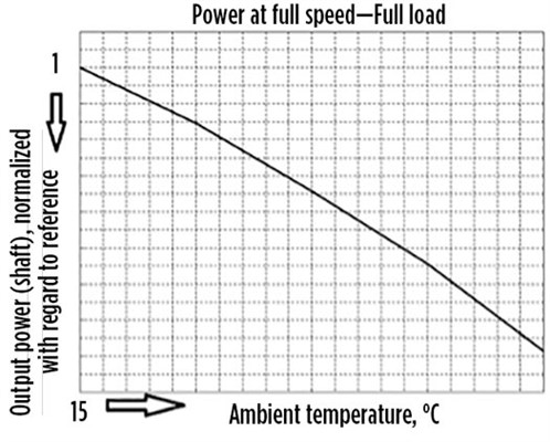 |
| FIG. 2. Gas turbine typical de-rating curve—power vs. ambient temperature.b |
Compressor arrangement. Until recently, LNG plants had a maximum of two main refrigerant compressor casings installed on the same shaftline, with a variable-speed starter motor usually added to single-shaft gas turbines. A longer and more complex shaftline will increase the complexity of the torsional analysis study, further to the inter-harmonic excitations from the variable speed helper motor, when they exist.
A successful step-out was applied in the Yamal LNG project (FIG. 3), where three compressor casings plus a variable-speed start/helper motor were installed on the same shaftline, which extended in length to 50 m (FIG. 4).
 |
| FIG. 3. Novatek’s Yamal LNG project in Russia. |
| FIG. 4. Three compressor casings on a common shaftline with a variable-speed helper motor. |
The use of a gearbox will also lead to power losses that must be taken into account. Almost 2% of transmitted power could be lost due to the gearbox; however, it must be noted that technical improvements are ongoing to reduce such losses. The addition of a gearbox to the shaftline will also impact the CAPEX of the project, noise emissions and the maintenance of the compressor shaftline, especially if a gearbox noise hood is added to meet noise specifications.
Depending on the size of the driver, one or several compressor casings can be installed on the same shaftline, and the temptation can be great to limit the number of shaftlines for CAPEX purposes. Selecting a bigger driver with several compressor casings, instead of selecting several smaller ones to drive one compressor casing, might seem to be less expensive from a machine perspective. However, the CAPEX savings of this selection is less obvious if the complete installation of the train is considered.
Applying large gas turbines would lead to a horizontally-split design for the middle casing to enable maintenance of the compressor rotor. This casing will have a bottom/bottom nozzles configuration so that the upper half of the casing can be opened to extract the rotor. This will require mounting the entire shaftline on an elevated table, as shown in FIG. 5. For modular applications, it will lead to an increase in the size of the module, and when installed in a closed building it will lead to higher building elevation and increased heating, ventilation and air conditioning (HVAC) load. All of these factors might eventually make the larger gas turbine more expensive than several equivalent smaller ones.
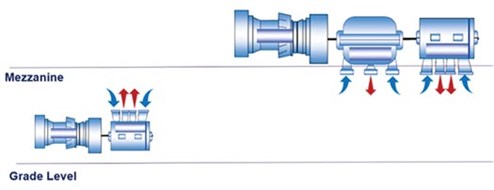 |
| FIG. 5. Grade-level vs. mezzanine-level installation of the shaftline. |
Gas turbine technologies. Historically, heavy-duty gas turbine drivers have been selected to drive LNG compressors considering their robustness, and consequently their high availability levels; accordingly, a 1 × 100% shaftline arrangement was considered (for example, in the Yemen LNG project). However, with an aeroderivative (or dual-shaft heavy-duty) gas turbine, parallel operation (i.e., 2 × 50% shaftlines) was introduced to overcome the smaller sizes available in terms of power output and to limit the impact on production due to lower availability. In addition, the 2 × 50% (or 3 × 33%) shaftline arrangement can improve the turndown efficiency of the liquefaction unit.
Turndown capacity of a compressor, before the start of recycle, is generally considered at 30% of the rated flow, which is sometimes insufficient for process purposes if only one compressor is used.
Efficiency. One of the main advantages of aeroderivative gas turbines is the much higher operating efficiency compared to heavy-duty gas turbines. This efficiency is the result of the higher pressure ratio developed by the axial air compressor and, consequently, the greater gas expansion in the power turbine. In the specific case of the triple-shaft LMS-100 from Baker Hughes/General Electric, intermediate air cooling allows exceptional axial air compression ratios and an efficiency reaching 44%.
However, the selection of the gas turbine will directly impact the design of the fuel gas system of the plant and particularly the size of the boiloff gas compressor, as the fuel gas pressure requirement will be higher for an aeroderivative gas turbine compared to a heavy-duty gas turbine, which depends on the selected gas turbine model and ambient conditions. Roughly speaking, heavy-duty gas turbines require fuel gas pressure around or below 30 barg compared to aeroderivative gas turbines, where the fuel gas pressure can range from 42 barg–60 barg, such as for the SGT-A65 (Trent 60) from Siemens, which is no longer in production.
Shaft arrangement/speed variation. Most heavy-duty gas turbines come in a single-shaft arrangement (FIG. 6), although some exceptions exist, such as the Frame-5 from Baker Hughes/General Electric and the H-100 from Mitsubishi Hitachi Power Systems. However, aeroderivative gas turbines come in a multi-shaft (dual- or triple-shaft) arrangement (FIG. 7).
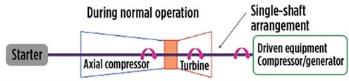 |
| FIG. 6. Single-shaft arrangement in gas turbines. |
 |
| FIG. 7. Dual-shaft arrangement in gas turbines. |
Accordingly, aeroderivative gas turbines operate at a wider speed range of 80%–105% of the rated speed and do not require a large starter motor, while speed variations in heavy-duty gas turbines are limited to 2%–3% of the rated speed and require a large starter motor to spin the heavy shaftline from standstill to firing speed.
CAPEX. Aeroderivative gas turbines are naturally more expensive than heavy-duty gas turbines due to the additional axial compressor stages and higher compression ratio (and compressed air temperature) that require the use of exotic material, such as titanium alloy, whereas stainless-steel alloys are sufficient in heavy-duty gas turbines.
A second consequence is that there are roughly 30% more internal components for an aeroderivative gas turbine compared to heavy-duty gas turbines of the same power class.
Varied onshore/offshore applications. Aeroderivative gas turbines are much lighter and more compact compared to heavy-duty gas turbines, which is why aeroderivative gas turbines are the preferred choice for offshore applications. They have consequently been selected for all FLNG vessels. The PGT25+G4 aeroderivative turbine is less than one-third the weight of its equivalent heavy-duty gas turbine, the Frame-5D.
Onshore LNG plants applied heavy-duty gas turbines until the LM2500, an aeroderivative gas turbine that was used at the Darwin LNG project to improve efficiency. Many other projects have followed, including Curtis Island LNG, Papua New Guinea LNG, Wheatstone LNG (with an LM6000PF turbine) and, recently, the Arctic LNG 2 project, which is still under construction, with an LM9000 turbine.
For offshore applications, the PGT25+G4 gas turbine from Baker Hughes/General Electric’s LM2500 family has been applied at the Coral South FLNG (FIG. 8), which operates on a dual mixed-refrigerant process. The PGT25+G4 has been also applied at Petronas’ PFLNG Satu, which operates on an AP-N process, as well as several other FLNG facilities, such as Golar FLNG vessels and the Gorskaya FLNG. An LM6000PF, another aeroderivative gas turbine, has been applied at Petronas’ Rotan FLNG to deliver roughly 30% more output power compared to a PGT25+G4 gas turbine.
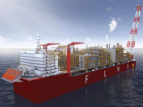 |
| FIG. 8. The Coral FLNG project. |
Shaftline power enhancement. Aeroderivative gas turbines are more sensitive to daily and/or seasonal fluctuations in air temperature than heavy-duty gas turbines. To compensate for periods of high ambient temperature, inlet air chilling can be used to mitigate the slight adverse impact on output power. When the power shortage is high at hot ambient, a helper motor is applied to supplement the power shortage from a heavy-duty gas turbine.
Waste heat recovery unit. A waste heat recovery unit (WHRU) can be fitted at the exhaust stack of the gas turbines for the main refrigerant compressors when the power margin between gas turbine output power vs. driven compressors absorbed power allows. Roughly speaking, adding a WHRU could lead to an approximate 0.4% drop in output power of the gas turbine, depending on the operating conditions and the design of the WHRU.
Maintenance considerations. Maintenance intervention is more frequent but less time-intensive for aeroderivative gas turbines compared to that required for heavy-duty gas turbines. Dual-shaft gas turbines, in general, are much easier to maintain. General Electric’s Frame-5 is an example of a heavy-duty gas turbine with a dual-shaft arrangement.
A new generation of large, dual-shaft, heavy-duty gas turbines has been initiated with the introduction of the MHPS H-100 for use in LNG plants. This turbine offers shorter shutdowns for maintenance. In addition, the dual-shaft design eliminates the need for a large starter motor.
Novelty management. The adoption of new, unproven technologies should be avoided wherever possible. However, the increase in LNG train size and the interest in scale as a way of reducing CAPEX sometimes leads to gas turbines being selected while still in the development phase, and with risks that are still under assessment by the gas turbine manufacturer.
An example of a new development is Baker Hughes/General Electric’s LM9000 aeroderivative gas turbine, which is based on the GE-90 aircraft engine. As a two-shaft machine with ISO shaft power reaching approximately 70 MW, it is capable of revolutionizing upcoming LNG plant designs. The adoption of the LM9000 on the Arctic LNG 2 project implied a qualification program and additional studies, simulations and tests during the engineering phase of the project.
A “technology qualification” process consists of an in-depth analysis of the design, development and integration of new or borrowed technologies to identify risks and implement mitigations. The process follows a structured procedure to identify and screen novelty designs within a new product and assess the readiness level of each novelty. This qualification program is normally led by the owner-operator and is based on the owner’s internal processes and field experience.
A first step in such a qualification process is the identification, component by component, of all novelties within the gas turbine design. Examples include a new material or coating, a new production process, new operating conditions or a combination of these items. Once identified, and after technical validation is performed, a risk mitigation plan must be established. This will often result in demanding tests such as a full-speed, full-load string test or an endurance test, which must be taken into account in the overall schedule of the project.
Takeaway. Turbomachinery selection for LNG plants encompasses several steps of screening to reach the optimum driver and compressor configuration choice. This broad choice is impacted by the unique aspects for each LNG plant, including the production capacity, train size, CO2 emissions and other environmental targets, site location (particularly when not onshore), site ambient conditions and variations, demand for utilities, availability of electrical power from the grid and the need for waste heat recovery.
A successful selection process is a joint effort between the owner and a specialized LNG engineering contractor. The optimum selection of driver and compressor configuration is achieved through a comprehensive assessment by an interdisciplinary team of engineers and estimators. GP
ACKNOWLEDGMENTS
The authors of this paper thank the TechnipEnergies LNG product line and the Paris Engineering and Process Department management for sponsoring this paper for the GPA Europe Annual Meeting and Technical Meeting in 2020.
NOTES
a This article was originally presented at GPA Europe’s Annual Meeting and Technical Meeting in 2020.
b X-axis and y-axis values are not shown due to copyright reasons.
 |
MOUNIR MOSSOLLY is Technical Advisor and Lead Engineer at TechnipEnergies and the Honorary Chairman of IMechE Groupe France. He is a Chartered Engineer and a Certified Manager of Quality and Organizational Excellence by ASQ. In the context of his expertise in turbomachinery, Dr. Mossolly has been involved with some of the largest, most complex and most challenging LNG projects worldwide, such as the pioneering Prelude FLNG, Yamal LNG and Coral FLNG. At present, he is working on the Qatar North Field Expansion EPC-1 LNG project. Dr. Mossolly holds a PhD in project and program management and an MS degree in mechanical engineering.
 |
CELINE BELBOL is Head of the Rotating Equipment Department at TechnipEnergies Paris, and has more than 17 yr of experience in the energy industry. She started her career with Technip as a Rotating Engineer and progressed to the position of Team Leader Engineer before being appointed Head of the Rotating Equipment Department. She gained her technical experience through involvement in various onshore and offshore oil and gas projects and through team management of complex mega-LNG projects, such as Yamal LNG and Coral FLNG.
 |
VINCENT TIRILLY is a Principal Process Engineer in the Process and Technologies Division of TechnipEnergies’ LNG Department. He is also a Member of the Expert Network from TechnipEnergies with more than 25 yr of experience in onshore and offshore LNG projects. Mr. Tirilly has been involved in all stages of LNG project development, from early conceptual stage to FEED and EPC, including for the Coral FLNG and Qatar’s North Field East and North Field South projects.


Comments