
Dry gas seal failure analysis and reliability improvement
Dry gas seals (DGSs) are comprised of many delicate components used for sealing and are used on axial/centrifugal/screw compressors and turboexpanders in various industries. DGS failures are the greatest cause of compressor downtime—in the author’s experience, about 48% of compressor failures are due to DGS failure. To avoid this, it is essential to apply the correct DGS for the desired and appropriate function, and to analyze the cause of failure in a systematic way.
However, even if a DGS is selected correctly, it can fail more quickly than anticipated. This article addresses a systematic approach to DGS failure analysis based on the author’s experience.
The DGS is a pressure-balanced, gas-lubricated, end face seal in which the sealing mechanism is comprised of two faces: one stationary and the other rotating with the compressor shaft. The stationary seal is called a seal stator, primary ring or spring-loaded face. The rotating face is called a seal rotor, mating ring or seat. The rotating face is etched with grooves partially across the face that, in conjunction with the seal balance, create face separation by both hydrostatic (pressure) and hydrodynamic (shear) forces. Face separation is typically a 3-micron–5-micron (3-µ–5-µ) gap (see FIG. 1 for a better understanding of the size)1; however, depending on the design, service, application, etc., the gap may be changed. Leakage across the faces is a function of pressure differential, temperature, physical properties of the gas, seal size, seal geometry and rotational speed for a given seal design.
 |
| FIG. 1. The size of a micron (µ) compared to bacteria.1 |
American Petroleum Institute (API) 6922 includes definitions, nomenclatures and detailed information about different types of DGS. API 692 includes four types of DGSs: single-seal, double-seal, tandem-seal and tandem with intermediate labyrinths. Double-seal DSGs are normally used in highly toxic or abrasive process gases or where there is a very low suction pressure. Double-seal DSGs work at low pressures with a nitrogen seal gas supply.
FIG. 2 shows a tandem-seal DSG with intermediate labyrinth configuration with a process side seal and a non-contacting bushing separation seal, which consists of two single seals arranged in series separated by a labyrinth. Tandem-seal DSGs with intermediate labyrinth are suitable for medium- and high-pressure applications (e.g., > 82 barg) where leakage of process/seal gas to the atmosphere is unacceptable.
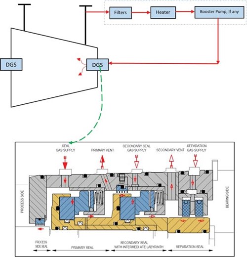 |
| FIG. 2. Tandem seal with intermediate labyrinth schematic, API 692.2 The blue dashed line is the boundary of the DGS panel. |
Seal gas is injected between the process side seal and the primary seal faces. The majority of the seal gas flows into the compressor and a small amount flows across the primary seal faces. The seal gas pressure is reduced across the primary seal to primary vent pressure. The intermediate labyrinth provides a restriction between the primary and secondary seal. Secondary seal gas is supplied between the intermediate labyrinth and secondary seal to provide a barrier and prevent primary seal leakage from reaching the secondary seal. Leakage from the primary seal is diluted with secondary seal gas and routed to a vent system. Secondary seal leakage is reduced across the secondary seal to atmospheric pressure and typically routed to the atmosphere. In case of primary seal failure, the secondary seal is designed to operate at primary seal conditions, which prevents uncontrolled leakage to the atmosphere and achieves a safe shutdown of the compressor.
Double-seal DSGs are used for highly toxic or abrasive process gases or where there is a very low suction pressure. Normally double-seal DSGs work at low pressures with a nitrogen seal gas supply.
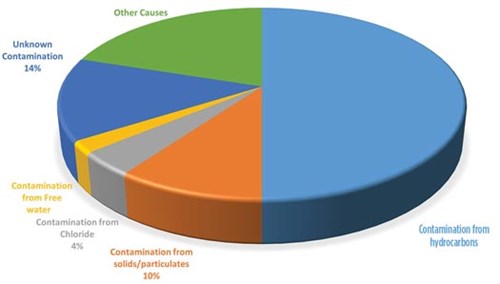
Dry gas seal failure statistics. According to a John Crane webinar training DGS failure course, DGS failure statistics are shown in FIG. 3, which indicates:
 |
| FIG. 3. DGS failure statistics. Source: John Crane webinar training course, July 2020. |
- 80% of DGS failures are due to significant contamination
- 50% by hydrocarbon (either liquid from the process gas or lube oil from the bearing housings)
- 10% of failure related to solid/particulates contamination due to dirty pipework, incorrect or poor filtration of the primary, or secondary gases supply to the faces
- 4% by chloride content of the process gas
- 2% due to free water from the process gas
- 14% due to unknown contaminations.
Data collection. In any root cause analysis, data collection is vital. An effective root cause analysis cannot be conducted without searching, interviewing, going to the site, conferring with various departments, etc. Reliability engineers should be aware that the opportunity for data collection will be lost when the DGS is removed from the compressor, so data collection must begin as soon as a work order is generated. Reliability engineers should collect the full details of “actual” operating data at the time of failure. The following information should be collected:
- Start/stop condition and history
- Vibration trend of the machine
- Cartridge pressure test
- Cold standby duration
- Hot standby duration
- Dynamic failure (i.e., failure below the 1-hr initial running time)
- Operating hour
- Sudden failure or progressive leakage increase
- Alarm/shutdown setting
- Any Management of Change (MoC)
- Storage time
- Any change in operational condition
- Dimensional checking and change
- DE/NDE condition
- Any unusual condition
- Any deviation from normal procedure.
Dry gas seal components analysis. The causes of DGS failure are identified to help reliability and maintenance teams mitigate and avoid future failures. Although wear is a potential cause, the author’s industry experience indicates that this is only the case in ˜10% of mechanical seal failures.
To correctly determine the root cause of a mechanical seal failure, reliability engineers should utilize evidence to form an accurate seal failure analysis. FIG. 4 includes some questions that should be asked when reviewing a mechanical seal failure.
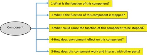 |
| FIG. 4. Five questions for DGS component analysis. |
Contamination by process gas.FIGS. 5 and 6 illustrate ways in which the DGS cartridge can be contaminated by process gas, particles or liquid. If it is assumed that the compressor gas is clean, the question may arise as to why the primary seal gas supply is necessary. The compressor gas can leak from the inter-stage labyrinth toward the DGS. Can that leaked gas be used instead of the primary seal gas, and why is spending required for a dry gas seal condition skid?
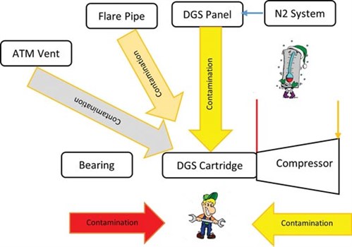 |
| FIG. 5. DGS contamination (process gas, liquid and particles). |
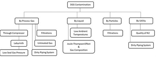 |
| FIG. 6. Main causes of DGS contamination. |
The answer is that the gap between the primary ring and the mating ring is about 3 µ (the size of bacteria), so the gas must be filtered to maintain the gap without damaging the surfaces. The gas inside the compressor is too dirty to be used directly into the seals, as this gas comes from carbon steel piping and vessels. The control and monitoring system is designed to provide a positive differential pressure so that filtered gas can prevent a migration into the seal directly.
The DGS is a non-contact seal, meaning that the faces are separated by a gas film of 3 µ–5 µ when the compressor is running and before startup. To lift the faces, a seal gas supply of minimum 5 barg–6 barg pressure is continuously and steadily injected between the faces. This depends on a number of factors, such as curvature, groove depths, size, etc. Sometimes this value may be lower.
However, when the compressor is unpressurized and in cold standby condition, the faces are in contact. If the compressor is shutdown under gas pressure, a “settle-out pressure” will still be applied to the inboard seal. This will provide lift and a gap preventing face contact. Normally, settle-out pressure is higher than the minimum lift up pressure, but the seal can still operate if it is equal.
In a hot static condition, the temperature must not decrease to an unacceptable level where liquids will drop out of the gas, causing problems and damage. If an intermediate labyrinth and secondary seal gas are used, this will provide lift and a gap to the outboard stage. If no pressure is acting on either sealing stage, the seal will be closed with no gap. Prior to restart, pressure must be applied to the seal to prevent the sealing surfaces from rubbing against each other.
During compressor shaft alignment with the gearbox shaft or driver shaft using dial gauges or laser alignment devices, the shafts can be rotated when the seals are unpressurized. The shaft must be rotated in the correct direction; this will not damage the sealing surfaces. The shaft will rotate statically with no pressure acting on the seals. Normally, a device is supplied to manually rotate the shaft—this is possible even on large-diameter shafts. It is highly recommended to clarify with the DGS manufacturer and follow the DGS’s operating manual. The author has experienced no damage to the face surfaces when the compressor shaft is hand-rotated with no pressure.
Case study: Contamination with lube oil. During commissioning of a centrifugal gas compressor, the oil pump started flushing oil, bypassing the permissive signal and without any separation gas due to a lack of utility. The DGS cartridges were heavily contaminated with lube oil. During operation, an engineer noticed errors made by the contractor and realized it was fortunate the compressor did not start.
When liquids form between the seal faces or oil reaches the faces while the compressor is not rotating, they may stick together. The flat surfaces of the stationary face and the rotating seat are within two light bands of flatness. With such flat surfaces, the liquid will create a bond between the stationary face and the rotating seat. This is beneficial as it will reduce or even eliminate the seal leakage. Conversely, the strength of the bond is so great that when rotational force is applied to the seat, it will damage the drive pins and the stationary seat. This causes high seal leakage during compressor start or restart and identifies a seal failure and replacement requirement.
If liquids enter the gap between the rotating seat and stationary face, high shearing forces are created that generate high heat. The generated heat leads to gap instability, causing contact between the rotating seat and stationary face, damaging the seal faces and resulting in seal failure. If a failure does not occur during operation with the liquid contamination, the seal will fail at the next subsequent start due to increased shear forces. In a wet mechanical seal, oil film will lubricate and cool the faces; however, with a DGS, the oil film will damage the faces and generate high heat. The oil will burn and create a massive amount of heat, resulting in a fracture of the mating rings.
In this case, all components and parts of the contaminated DGS cartridges were removed from the compressor casing, disassembled, cleaned carefully and then reassembled and reused without any problem. It was unnecessary to send the cartridges back to the vendor for cleaning, inspection, balancing, assembly and testing. The case would be different if the compressor was started with contaminated DGSs. In that case, the cartridges should be sent to the vendor, as they would be damaged after compressor startup due to high shear and massive heat generated due to the lube oil.
Causes of mating rings contact. There are two main causes of mating rings contact: no lift and forced contact. Lifting the mating rings requires minimum gas pressure between the faces and minimum shaft speed. Leakage in static and dynamic conditions may occur.
The lift of speed is different between unidirectional (2.3 m/sec) and bidirectional (3.5 m/sec) DGSs. In static conditions, such as settle-out condition, slow-run and shutdown conditions, lift off between the rotary/mating face and stationary face is provided by gas pressure only. In dynamic condition, the seal requires less pressure because the shaft rotation sucks the gas into the grooves and generates a high-pressure area between the faces.
During the design stage, the minimum speed for the faces to lift off is calculated based on compressor operating conditons by the seal manufactuerer. This calculation ensures that lift off hapens before/at reaching slow roll speeds. FIG. 7 shows a slow roll diagram of the DGS based on gas pressure and speed.
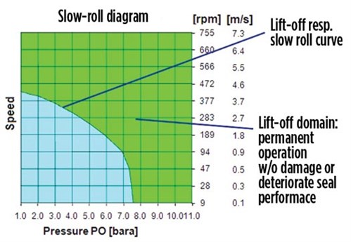 |
| FIG. 7. Typical slow roll diagram (DGS). |
Forced contact is where two faces have been forced to contact each other during normal or transient conditions (e.g., startup or shutdown). The result can be three types of contacts:
- Outer diameter contact of the mating rings: In this case, the lift-up may be loosened due to the high risk of groove damage in the rotating ring.
- Inner diameter contact of the mating rings: In this case, the lift-up may be possible due to a lowered risk of grove damage in the rotating ring.
- Full face contact of the mating rings: In this case, the lift-up may be loosened due to the high risk of groove damage in the rotating ring.
FIG. 8 shows some causes of the no lift, and FIG. 9 shows some causes of forced contact.
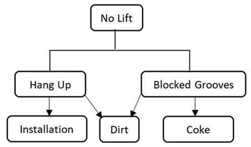 |
| FIG. 8. Causes of no lift. |
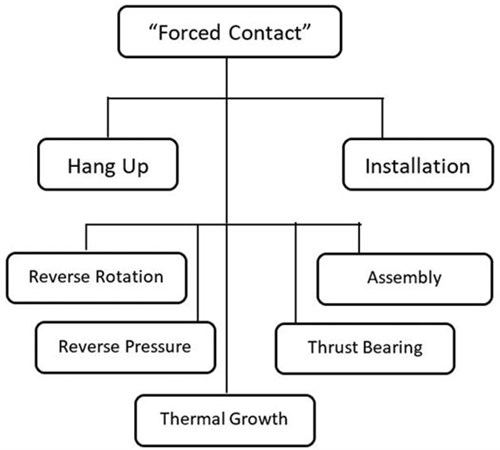 |
| FIG. 9. Causes of forced contact. |
Recommendations. The following considerations improve DGS reliability and prevent failure.
Slow run. If the compressor train requires a slow run to complete a cooling or warming cycle—mainly steam or gas turbines as per driver/compressor manufacturer requirements—the specific requirements should be communicated to the DGS vendor. A slow run normally takes 24 hr–36 hr with a speed lower than the lift off speed of the DGS and a lower discharge pressure, which impacts the primary gas seal pressure of the DGS. The seal may require special modifications on the grooves or engineered seal. In this case, temporarily disconnecting the compressor from rotation at low speed may be a solution with the help of a clutch mechanism, as a slow run is mainly required for steam and gas turbines.
Seal gas analysis. Regular seal gas analyses are highly recommended as part of a preventive maintenance plan, preferably on a monthly basis. A provision for sampling from the gas is highly recommended.
Trend analysis. Monitoring seal leakage, flowrates and vent pressure is very important. Out-of-specification leakage and flowrates are indicators of a faulty seal. Other observations of bearing vibration and abnormal temperatures are important indicators of DGS condition.
Oil atmospheric drain. Adding an oil atmospheric drain to the DGS cartridge will help notify the operator if the oil has migrated from the bearing housing to the dry gas seal. Monitoring the trend of separation gas pressures and flowrates are also kety indicators if oil has been leaked to the DGS.
Choose the correct seal faces material. When the rotary and stationary seal faces touch due to a lack of gas pressure or enough shaft speeds, a rubbing and frictional contact simultaneously generates high heat. Selecting the correct seal rings ensures reliability—the seal rings must be hard, rigid, chemically resistant, thermally conductive, tough and wear resistant. Tungsten carbide is a popular seal ring material, and is made by heating tungsten carbide powder and a metallic binder (i.e., cobalt and nickel) to 1,500°C to melt and fuse the binder. Check the chemical compatibility of nickel and cobalt when using tungsten carbide in a DGS. Strong acids can attack binders, causing cobalt formation at the seal faces and premature seal failure. Use proper seal gas with the gas conditioning unit and change the seal material to silicon carbide if a risk of cobalt formation exists between the seal faces.
Shaft lifting. During installation or removal of the DGS cartridges, it is necessary to lift the compressor shaft a few times. This may damage the DGS. Review the procedures and tools with the compressor and DGS manufacturers. Minimize the shaft lifting during installation/removal of the DGS cartridge by using specially engineered components and parts. For example, check if split metallic rings might work instead of solid rings to fix the cartridges to the casing.
Filter cleaning. Do not clean the filter elements in a DGS panel with solvent or air, and reuse them (when possible) to save money. Always follow the OEM’s recommendation.
API 692. Ask the vendor to follow API 692. While API 6143 contains 35 pages of information regarding DGS systems, API 692 has almost 100 pages in four parts. Part 3 was written to specifically address design issues related to a DGS support system and includes predefined P&ID modules to build systems to suit the application. Annex D of API 692 provides criteria for the selection of different types of DGSs. This standard is becoming more popular with new projects compared to API 614.
System cleanliness. Check the cleanness of all components within the DGS panel, including piping material. It is recommended to use stainless-steel piping to connect the panel to upstream and downstream systems (flare, vent, compressor discharge pipe, etc.) whenever possible. Check internal surface cleanliness of the piping and gas channels in compressor end walls with a professional borescope and perform chemical cleaning where needed.4
Risk of condensation. Check and monitor the risk of condensation during all operating conditions, especially standby conditions under settle-out pressure. To avoid condensation, a gas conditioning unit with a gas heater should be used to keep the gas temperature above the dewpoint in all conditions. Considering low ambient temperatures, the need for winterization with electrical heat tracing should be studied. A provision for using warm nitrogen may be required, as well. Consult with the seal vendor as to whether a double-seal DGS has an advantage compared to a tandem-seal DGS to mitigate the risk of condensation. Double-seal DGSs use nitrogen as seal gas, so the gas temperature may not an issue. The use of a coalescing filter will help to separate liquid from the gas; however, liquid can be dropped out after passing the gas inside the cartridge from the intermediate labyrinth or between seal faces due to the Joule-Thomson effect.
Restriction orifices. The primary gas vents contain orifices that keep the gas film between the faces. Ensure that they are installed before the initial compressor startup or after turnaround. Without those orifices, the primary seal will fail. The location and elevation of those orifices are important compared to the compressor shaft center.4 GP
NOTE
The recommendations outlined in this article are based on the author’s experience and are not related to any company.
LITERATURE CITED
- Online: https://www.freshwatersystems.com
- American Petroleum Institute (API) Standard 692, “Dry gas sealing systems for axial, centrifugal, rotary screw compressors and expanders,” 1st Ed., June 2018.
- American Petroleum Institute (API) Standard 614, “Lubrication, shaft-sealing and control-oil systems for special-purpose application,” 5th Ed., May 2008.
- Zardynezhad, S., “Achieve successful compressor startup by addressing dry gas seal failure,” Gas Processing Journal, November/December 2014.
 |
SHAHAB ZARDYNEZHAD is a registered Senior Mechanical/Pipeline Engineer in Alberta and British Columbia with more than 29 yr of experience working in the world’s largest oil, gas and petrochemical projects. He has experience in engineering, procurement services, manufacturing, installation, commissioning, startup, reliability, maintenance and operation of pumps, compressors and turbines. He holds a BS degree in mechanical engineering from the University of Petroleum of Iran, an MS degree in industrial engineering from IUST Iran, and MS degrees in mechanical engineering and project management from the University of Calgary in Canada. He is also a certified API inspector for rotating equipment.


Comments