
Use a seven-step procedure to mark piping CMLs
Piping is considered one of the most valuable assets in any hydrocarbon processing facility. Many meters of piping run through these facilities, transporting process fluid from one unit to another. The integrity of piping systems is as important as that of any other asset in the facility; however, when studying piping systems of different sizes, metallurgy and lengths, it is important to consider inspection plans that are not only effective but also efficient with respect to the effort required. Marking more condition monitoring locations (CMLs) than necessary wastes time and effort, but marking far fewer CMLs than needed puts piping integrity at risk.
Several guidelines are available to define the CMLs on a given piping system; however, the plant inspector has the ultimate control over defining, inspecting and redefining the CMLs throughout the piping life. This is a continuous process (FIG. 1), and balance can be achieved only after at least one full round of design life is finished with no loss of process containment. Data from similar operators may help achieve a balance to the piping inspection, which is normally the first step in defining CMLs for any piping system. A stepwise approach in defining, inspecting and redefining CMLs on any piping system is detailed in the following sections.
 |
|
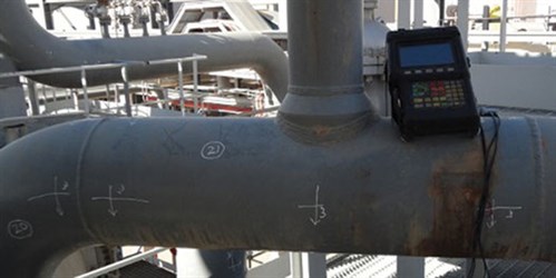
FIG. 1. General work view of a piping inspection. |
Step 1: Data from similar operators. Sharing data between industries and companies worldwide is not uncommon, but it can be difficult to organize. Nonetheless, if a data-sharing arrangement can be made, information from similar service operation can help in many ways.
Of significant usefulness are comparable CMLs marking data for piping systems in similar service. These provide a quick start for other operators to launch this continuous process. If already normalized for a given piping system at a hydrocarbon processing facility, verified CMLs can save massive effort for a new operator. However, if such data is not available or not easily obtained, then this step can be skipped.
Step 2: Identification of credible damage mechanisms. Information on credible damage mechanisms must be obtained before starting work to define the CMLs on any piping system. If a risk study has already been performed for the facility, then this document may contain the relevant information.
Step 3: Define inspection tasks. Inspection tasks must be defined after information on credible damage mechanisms is made available. These inspection tasks can provide a way forward for marking appropriate CMLs. In most cases, inspection tasks for piping include measuring the wall thickness to identify different forms of corrosion. Most CMLs are marked to perform ultrasonic inspection tasks.
Step 4: Corrosion rate determination. When designing a piping system, an initial design corrosion rate is always considered to define the lifespan of a piping system. This critical information defines the corrosion allowance. For all piping systems, the initial design corrosion rate must be tabulated to determine the actual corrosion rate.
To determine the actual corrosion rate, initial marking of CMLs should be done only on baseline thickness locations, if available. If baseline thicknesses have not been measured, then CMLs should be defined at bare minimum locations to enable the inspector to determine the actual corrosion rate.
The initial inspection frequency can be increased so that this exercise can be completed. A round of three inspections should be sufficient for accurately calculating the corrosion rate of any piping system.
Step 5: CMLs placement. An inspector must evaluate the placement of CMLs based on several factors:
- Credible damage mechanism
- Inspection task
- Design corrosion rate/allowance
- Piping geometry
- Piping accessibility.
Services that are not safety-critical upon loss of process containment should be separated and, by default, only one CML in each 60-m run of piping should be defined. However, all other services that are declared process-critical should be examined in detail, considering the previously listed factors.
Any damage mechanism that is general in nature should result in fewer CMLs; however, damage mechanisms may change with changes in piping geometry or piping tags, resulting in varying process conditions and more CMLs, as a general rule. A single run of piping with similar process conditions throughout, with no changes to temperature, flow or other process conditions, does not need to be inspected at many locations. Conversely, piping runs with many branches bring changes to existing process conditions, which may impact the credible damage mechanism and require inspection at multiple locations.
The type of inspection task to be performed on a given CML also impacts the total number of CMLs. Ultrasonic thickness inspection, the most common task performed on piping, gives only the data related to corrosion or pressure boundary thickness. Other necessary inspections may include temperature monitoring at desuperheater locations or profile radiography to search for debris accumulation at piping deadlegs. CMLs to monitor such conditions are specific and largely unlimited. Wall thickness measurements, obtained through ultrasonic thickness testing, can be limited or controlled to some extent.
During the project design phase, the definition of corrosion allowance for any piping system is given after carefully studying the anticipated corrosion rate of the metallurgy put into service, with reference to a defined design life. The corrosion allowance definition should be respected; however, it should also be reviewed and verified—this is the core work of the inspection team monitoring the piping systems.
When CMLs are defined for corrosive services, an appropriate metallurgy and corrosion allowance combination for the design life must also be in place. Careful attention must be paid to the verification of this combination through minimum CMLs.
Step 6: Field marking. CML markings on isometrics should be replicated as closely as possible in the field. This becomes especially important when data must be analyzed and CMLs must be redefined. Inaccuracy in positioning the CMLs can result in incorrect or irrelevant readings for the analysis. When looking into the records of any industry, the data from a single, incorrectly located CML can be seen to follow an erroneous pattern over time.
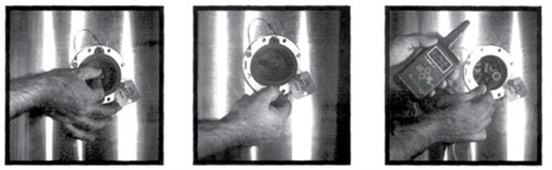
Field marking of CMLs is of utmost importance and can be achieved through many ways, including in-house resources or external support. Insulation demands more work than bare piping; however, it should be kept in mind that marking CMLs is a one-time activity for as long as the CMLs remain the same. Solutions (FIG. 2) are available for each marking requirement including piping, thin insulation, thicker insulated tanks, vessels, hot service and even cryogenic processes.
 |
|
FIG. 2. Inspection port shown as an example for CML reading. |
Step 7: Performing inspection on CMLs. After CMLs are defined, the core business of recording the actual readings starts. How to take these readings is of utmost importance. A more relative term used for thickness recording is thickness monitoring locations (TMLs). If a CML is defined only for thickness monitoring, then TMLs can be defined for that specific CML.
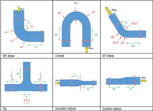
Each CML can have multiple TMLs. As a general rule, along a 360° band of piping, readings should be recorded at each quadrant, with each reading representing a single TML. Different recommendations are available to define TMLs on different CMLs in piping. One recommended definition for different piping configurations and fittings is shown in FIG. 3.
 |
|
FIG. 3. Typical TMLs for different piping fittings. |
Marking CMLs for all piping groups provides a baseline work for evaluating and maintaining piping integrity. When performing this marking work, each step as defined above should receive proper attention. Ignoring any of the seven recommended steps may lead to recording incorrect data that may not be representative of the piping integrity. GP
 |
ASHFAQ ANWER is an Inspection Engineer working in gas processing in Ruwais, Abu Dhabi, UAE. He has more than 14 yr of professional inspection experience in ammonia-urea complexes, petrochemical units, and oil and gas industries. He has extensive expertise in material selection, corrosion mapping and control, fitness-for-service studies, defining inspection framework and implementing inspection plans for old and new units.
 |
KAISER ALAM is an Inspection, Corrosion and MetallurgySpecialist with more than 7 yr of experience in static equipment inspection, fitness for service, material selection, and inspection strategies and procedures. His experience is predominantly in the downstream oil and gas industry in the Middle East.


Comments