
Introduction to oil bearing turboexpander rotor dynamics
Turboexpanders are the ideal choice for processes with large pressure drops that require refrigeration or power recovery. Whereas a valve or orifice also can be used to effectively drop pressure, turboexpanders extract useful work from a flowing gas stream. Isentropic efficiencies as high as 90% are readily achieved with a turboexpander, resulting in much lower discharge temperatures.
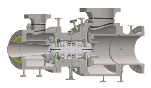
Turboexpanders were introduced in the mid-1930s when the first machine was designed and implemented for air separation. The first unit for a natural gas application was designed and installed in the early 1960s. Over the years, many technological advances in design and manufacturing have allowed these machines to contribute to improvements in the efficiency of gas processing plants. Today, turboexpanders are standard in the natural gas industry for liquefaction and dewpoint control (FIG. 1). They are also used in the petrochemical industry for ethylene plants, air separation, refrigeration and power generation. Their relatively simple construction and hermetically sealed design generally lead to high reliabilities, with some plants operating the same units for many decades. Today, more than 5,000 turboexpanders are in operation worldwide.
 |
|
FIG. 1. Typical turboexpander design. |
Like a steam or gas turbine, a turboexpander is a rotating machine with an expansion turbine that converts the energy contained in a gas into mechanical work.1 The work produced by the turbine is absorbed by a “loading” element that is mounted on the same shaft as the turbine. The loading element can be a dyno (oil brake), an electric generator or a centrifugal compressor stage. For the latter two, turboexpanders afford the opportunity to utilize energy that otherwise would not be available with a Joule–Thomson (J–T) valve. For instance, a compressor stage can be used as a pressure booster to meet a need in the process that otherwise would have necessitated a separate compressor driven by an electric motor or an engine.
In the authors’ experience, the more plant designers and end users understand about what is inside the “black box” of a turboexpander, the more successful they are when making critical decisions about their equipment. By being familiar with turboexpander rotor dynamic design, new machine designers and operators involved in a turboexpander project will be better equipped to fulfill their roles. The goal of rotor dynamic analysis is to ensure that catastrophic failure of a turboexpander does not occur due to vibration instabilities.
This article is meant to aid end users as they engage with turboexpanders, either at the procurement or operational stage, and offers an overview of turboexpander rotor dynamics, suggestions for what to look for from original equipment manufacturers (OEMs), and a case study describing the typical data presented in a turboexpander rotor dynamic design document.
The purpose of rotor dynamics. The field of rotor dynamics is concerned with the motions and associated forces of rotating shafts. In the study of rotor dynamics, emphasis is placed on five degrees of freedom, or types of motion, spanning lateral and torsional. Lateral motion is perpendicular to the shaft’s rotation axis (the X–Y plane shown in FIG. 2). This includes translations in the X and Y directions and rotations about the X and Y axes. Torsional motion is rotation about the shaft’s rotation axis—the Z axis. Axial motion in the Z direction is typically neglected for machines supported in oil bearings, which is the focus of this article. Note: Axial motion in the Z direction is not neglected for active magnetic bearing control systems, where they can play a significant role.
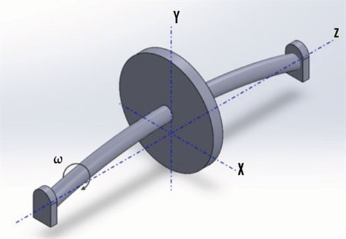 |
| FIG. 2. Simplified rotor schematic. |
Every turboexpander vibrates at some minimum level at least once per revolution because no rotor can be perfectly balanced. The OEM must, at a minimum, ensure that the design can tolerate the motions imposed by the residual imbalance in the rotor. Therefore, the primary objective of performing rotor dynamics analysis is to predict the motion of the rotor and ensure that the vibration levels are contained within acceptable limits.
Vibration limits may be set by available clearances between rotating and stationary components (e.g., bearings and seals), or by limitations on bearing load capacity. It is important to avoid operating near a critical speed, or natural frequency, to avoid very high amplitude vibrations and stresses.
Vibration limits can also be set by experience and empirical data. API-617, for instance, limits overall vibration to the lesser of 1 mil or √12,000/Nmc, where Nmc is the maximum continuous running speed of the machine. However, the OEM may find higher levels of vibration acceptable, depending on the type of bearing used, its clearances, and its stiffness and damping properties.
The term “critical speed” is worthy of comment. The definition of the term itself is not uniform across the industry. Therefore, it is important that the OEM and end user have a common understanding. For instance, API has slightly different definitions across different standards (e.g., API 616, API 617, etc.)
For the purpose of this article, the following definition is adopted: A critical speed is a shaft rotational speed at which the rotor bearing support system is in a state of resonance. This does not mean that a critical speed is necessarily an unstable operating point. A rotor running at a critical speed will normally run at elevated vibration levels. The level of vibration is inversely related to the amount of damping in the system. The level of magnification is known as the amplification factor. Rotor systems with sufficiently high damping, and therefore low amplification factor at around the critical speed, do not require any separation margin, or avoidance speeds, and therefore are typically ignored. As such, these sufficiently damped resonant frequencies are often not treated as critical speeds. Another reason for not considering sufficiently damped resonant frequencies is that they sometimes cannot be reproduced on the test stand.
Associated with critical speeds are their vibration modes, which are the shapes the shaft will take while running at a critical speed (FIG. 3). These mode shapes are commonly referred to as the first rigid (translatory or bouncing) mode, the second rigid (conical or rocking) mode, and the nth (first, second, third, etc.) bending mode.
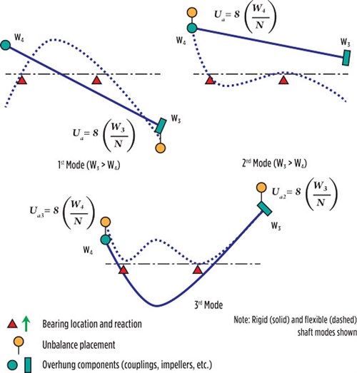 |
| FIG. 3. Rotor mode shapes (from API 617).2 |
It is not uncommon for engineering, procurement and construction companies (EPCs) or end users to request a rotor dynamics analysis report from the OEM for review during the design stage. The following section provides an overview of the components of such a report. For illustration purposes, results from an actual case study are included under each heading.
Case study machine. The machine in question is a 5,395-hp turboexpander processing approximately 170 MMsft3d of natural gas feed (85.7% methane, 9.3% ethane, 2.5% propane, etc.) at a supply pressure and temperature of 865 psia and –27°F. The expander is loaded by a centrifugal compressor stage handling a flow of mostly methane (97.9%) at a flow rate of 285.61 MMft3d and compressing at a pressure ratio of approximately 1.21. The rotor speed is 17,500 rpm at the design point, but it can fluctuate between +2.74% and –1.89% of that value, depending on the off-design operating conditions.
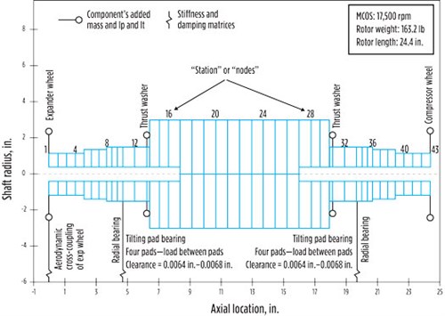
Rotor model. This machine was required to feature oil bearings. A rotor dynamic analysis (RDA) based on the finite-element technique was performed, using a commercial software to determine, among other issues, which design of radial oil bearings was most appropriate. The geometric model of the turboexpander rotor-bearing system is shown in FIG. 4.
 |
|
FIG. 4. Graphical depiction of the finite-element model for rotor dynamic simulations. |
The rotor consists of a solid shaft with one overhung wheel on each end. The wheels are computer numerical control (CNC) machined from forged aluminum alloy and attached to the shaft via a tight, slip-fit, polygon fit (which provides high precision alignment during operation) and secured with a fastener (which prevents any axial displacement or loosening). Fully assembled, the rotor weighs 163 lb and is approximately 24 in. long. The shaft diameter at the bearing location is approximately 3 in.
The contribution of the wheels depends on their mass properties, namely weight, polar inertia (around the shaft axis), transverse inertia (across the shaft axis) and the location of the center of gravity. Those values are added to the “node” or “station,” where the element is located on the shaft (see the legend in FIG. 4).
As for the bearings, their contribution consists of providing radial support stiffness to the rotor and attenuation of the vibrations. They are pictured in the model in FIG. 4 as springs. These are mathematically expressed as rotor speed-dependent stiffness and damping coefficient matrices.
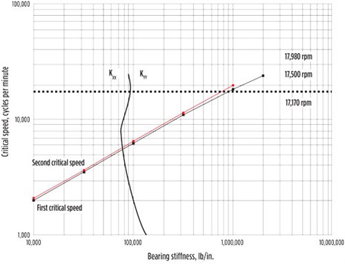
Undamped critical speed (UCS) map. A UCS map is a plot of critical speeds vs. bearing stiffness (FIG. 5). This plot identifies the critical speeds and their mode shapes, as well as how they vary with different bearing stiffnesses. As such, the UCS map provides the designer with a starting point in the process to choose the type of bearing needed. For example, for a stiffer bearing, the designer may choose fixed-geometry bearings with tighter clearances, whereas for softer bearings, the choice may be tilting-pad or flexible-pivot bearings with larger clearances. The goal in choosing a bearing is to avoid potentially exciting a shaft’s critical speed within the range of operating speeds required by the design of the turboexpander. FIG. 5 shows that a relatively softer bearing would be a better choice, considering that the critical speeds with stiffer bearings would be too close to the design speed.
 |
|
FIG. 5. Undamped critical speed map. KXX and KYY refer to the direct bearing stiffness in the horizontal and the vertical direction, respectively. In this case study, KXX = KYY. |
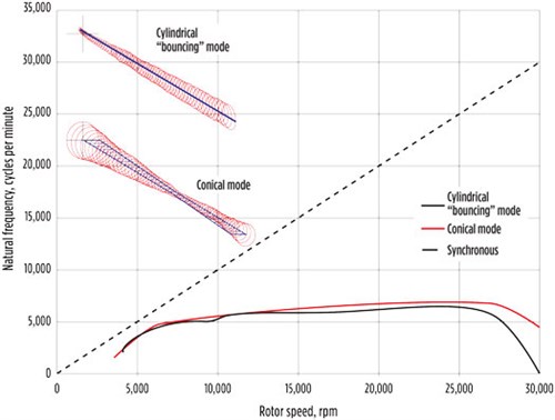
Damped natural frequency (eigenvalue) map. A damped natural frequency map is a plot of natural frequencies (eigenvalues) vs. running speed (FIG. 6). It is produced with models of the bearings, seals and any other excitation phenomena incorporated. This plot is useful for checking the likelihood of exciting a natural frequency in the operating range, as well as evaluating potentially unstable operating points.
 |
|
FIG. 6. Damped natural frequency map. |
A common characteristic of turboexpanders is that their shafts have a low aspect ratio, meaning they are quite short relative to their diameter. As a result, the natural frequency of the bending mode of these short, “stubby” shafts ends up much higher than their operating speeds or any excitation frequency. Therefore, from a rotor dynamics perspective, they are categorized as “stiff-shaft” designs.
The implication for stiff-shaft designs is that only the rigid body translational modes of vibration are of serious concern. These modes are greatly influenced by the design of the bearings. Smaller machines are usually equipped with tight-clearance, fixed-geometry bearings with high stiffness.
This yields a machine that does not have any critical speeds within its operating range. Larger rotors tend to utilize tilting-pad or flexible-pivot bearings and can be designed with larger clearances and lower stiffness. With this configuration, the machine tends to pass through a highly damped natural frequency at very low speeds. Since the bearings are well damped, these points of operation are not considered critical speeds due to the low amplification factor.
Two predominant modes of vibration are observed within the speed range, namely a cylindrical and a conical mode (FIG. 7). These results show that the rotor system is well designed since the natural frequencies for both modes do not intersect the 1X excitation line. Such a condition would have indicated a potential resonance situation.
 |
|
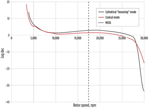
FIG. 7. Log dec plot. |
Stability analysis. It is not enough to know that damped natural frequencies do not cross the 1X excitation line. The designer must show that the bearing system is robust against the presence of destabilizing forces such as those induced by the areodynamic components, seals or bearings. It is also important to know how much damping is inherent in each vibration mode. Should insufficient damping be identified for a given mode shape, the rotor would be susceptible to high vibrations due to excitations such as unbalance. As mentioned previously, the bearings are the source of damping. However, the amount of “effective” damping is not the same for every mode. This is quantified by the so-called logarithmic decrement (“log dec”) or, alternatively, the damping factor. Designers typically prefer using one of these parameters for their analysis, but both are representative of the same physical reality.
FIG. 7 depicts the predicted log dec for the two predominant modes of vibration on this expander rotor. A minimum log dec of 0.1 implies that the system is sufficiently damped and can be considered stable. The data indicates that the log dec is positive for both modes from zero speed until MCOS. However, the log dec drops to negative values for speeds above 25,000 rpm, which indicates that the mode shape becomes unstable. This means that the system becomes self-exciting, and the vibrations will increase sharply. This is due to hydrodynamic effects in the oil film between the bearing and the shaft. This is clearly an undesirable condition, but it is not concerning in this case because the control system limits the maximum speed to protect the mechanical integrity of the machine.
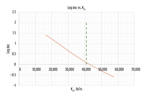
Also, note that the aerodynamic forces experienced by the wheels are transferred to the rotor bearing system and can sometimes add significant excitation forces, which must be considered in the calculation. The mechanism of these aerodynamic effects is such that they generate a displacement that is orthogonal, and not parallel as intuition might suggest, to the aerodynamic force. This phenomenon is modeled in mathematical terms as cross-coupled stiffness and can have the capacity to induce undesirable unstable vibrations. In many turboexpander cases, the destabilizing forces generated in the expander wheel are more consequential than in the compressor wheels. FIG. 8 shows an example on a different turboexpander in which the amount of aerodynamic cross-coupling created a significant instability.3
 |
|
FIG. 8. Influence of cross-coupling stiffness in log dec. KXX and KYY refer to the direct bearing stiffness in the horizontal and the vertical direction, respectively. In this case study, KXX = KYY. |
Bearing loads. Both static and dynamic loads on bearings can be predicted and are necessary in ensuring that the bearings, the bearing pedestals and the skid (i.e., the machine support structure) can handle the loads imposed on them.
Unbalance response plots. Until this point in the analysis, the designer has not accounted for excitation forces, such as unbalance. The unbalance in the rotor will generate a dynamic load at the same frequency as the rotation of the rotor (one excitation per revolution). The shape of the unbalance force will be related to the amount and distribution of unbalance (in terms of weight). Three unbalance weight configurations are typically considered in an analysis for any turbomachine, and they must follow API guidelines. The amount of balance is determined by the balancing tolerance applicable for each machine, and the unbalance weights are arranged spatially in such a way as to excite the predominant modes. A single weight in the middle of the rotor (which may be called a purely static unbalance) would tend to excite the cylindrical or bounding mode. A “couple” unbalance (i.e., one in which the weights are separated axially but opposite exactly 180°) will excite the conical or “hinging” mode.
The simulation in FIG. 9 shows the speed at which the vibration will peak as the rotor goes up in speed. This is the critical speed, and it is an important parameter to predict and monitor during field startup. The shape of the curve itself is important because it indicates the rate at which the vibration will increase as the machine ramps up. Well-damped, smoothly increasing curves with a wide base and a “dull” peak like the one pictured in FIG. 9 are preferable over one with a sharp and narrow peak. In the latter, which is a result of poor damping, the vibrations will quickly jump for a small increase of rotor speed, rendering the process of ramping up to speed somewhat unreliable and unpredictable. The shape of the curve is quantified by a parameter called “amplification factor.” From an API 617 perspective, those speeds with amplification factors greater than 2.5 are considered critical speeds.
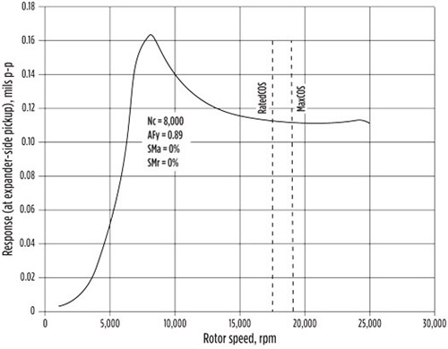 |
| FIG. 9. Rotor dynamic response plot. |
Another issue to consider is that the rotor must not run too close to the critical speed. The parameter to watch is the separation margin, which is the amount of separation between the critical speed (Nc) and the rated speed.
The data generated by the response analysis (i.e., vibration response magnitude and phase angle) can be validated with field measurements as long as the machine is equipped with proper instrumentation and data acquisition equipment, either in the field or in a factory test stand.
Clearance checks. The analysis must show that available clearances between rotating and stationary components are not exceeded, with considerations for margin. For instance, API 617 requires that shaft vibrations must not exceed more than 75% of minimum design diametral clearances.
In summary, a successful rotor dynamics analysis should ensure that the overall vibration levels will not exceed clearance or load limits, and that the overall rotor bearing system is stable throughout the operating speed range.
Conclusion. Rotor dynamics analysis is a key part of turbomachinery design. Ensuring that a rotor is stable and will operate within acceptable levels of vibration is necessary for long-term, reliable operation. API 6172 can be referenced for reviewing such an analysis to make sure that all parties agree to what defines a suitable design.
Ultimately, all rotor dynamic models should be verified on the test stand prior to operation in the field. Referring to a rotor dynamics analysis report during the evaluation of a mechanical run test is an important part of making sure that a machine has been manufactured and assembled according to design. More importantly, validation of the model on the test stand can provide assurance that the machine will operate as expected in field conditions.
As previously mentioned, the typical turboexpander should not present a significant rotor dynamic challenge for the OEM. These machines typically operate below significant shaft critical speeds, and minimal vibration can be expected given well-balanced components. In addition, instability is a rare issue with well-designed and manufactured bearings and seals.
After a machine has been commissioned, it is important for the operations team to collect vibration and bearing temperature data on a regular basis. These long-term trends prove invaluable when troubleshooting a vibration issue.
The most common rotor dynamics issue observed in the field is high synchronous vibration. Wearing components over time can contribute to rotor imbalance, steadily increasing vibration levels. Another common cause of imbalance increase over time is the formation of hydrates or other solids in expander wheels in cryogenic natural gas processing applications. Sudden, high levels of vibration can be attributed to major failures in either rotating components and/or bearings, such as blade loss in an impeller.
Other, more serious and difficult issues, such as rotor instability, will usually present themselves immediately during commissioning. These types of problems can be due to unforeseen (and unmodeled) process loads or poorly modeled rotor dynamics analysis. They are not easily solved by improving component balancing and usually require intensive efforts to redesign or add components, which can cause lengthy and expensive delays. For this reason, it is critical to ensure that a proper rotor dynamics analysis is performed during the design phase to rule out any possibility of rotor bearing instability. GP
LITERATURE CITED
- Avetian, T., “Fundamentals of turboexpander design and operation,” Gas Processing & LNG, May/June 2020.
- American Petroleum Institute, “API Standard 617: Axial and centrifugal compressors and expander compressors,” 8th Ed., 2014, API Publishing Services, Washington, D.C.
- Avetian, T., L. E. Rodríguez and J. Park, “Addressing high sub-synchronous vibrations in a turboexpander equipped with active magnetic bearings,” Proceedings of the 48th Turbomachinery Symposium, 2019.
 |
TADEH AVETIAN is Director of Engineering at L.A. Turbine, responsible for identifying and defining research and development projects, as well as directing turboexpander design for new and aftermarket equipment. Mr. Avetian is a California-registered professional engineer with BS and MS degrees in mechanical engineering from California State Polytechnic University of Pomona.
 |
LUIS E. RODRÍGUEZ is a Design Engineer at L.A. Turbine, responsible for the mechanical design of turboexpanders. Prior to L.A. Turbine, he worked for 10 yr at Sulzer Turbo Services in La Porte, Texas. Mr. Rodriguez is a Texas-registered professional engineer with a BS degree from Universidad Simón Bolívar in Venezuela and an MS degree from Texas A&M University.


Comments