
Improve gas-gas exchanger footprint and economics with a PSHE
Plate-type heat exchangers are known for high heat transfer coefficients. As a result, they are compact and lightweight compared to conventional shell-and-tube (S&T) exchangers. Another advantage of plate-type exchangers is a lower fouling tendency due to higher wall shear stress; however, the construction of widely used exchangers, such as gasketed and bloc-type exchangers, limits their application to low and medium design pressures (typically less than 50 barg). The plate-and-shell heat exchanger (PSHE) combines the advantages of plate-type exchangers with the robustness of the S&T exchanger into one exchanger. Design pressure can rise to 400 barg for the PSHE.
This article focuses on a specific application in upstream facilities where weight reduction and smooth operation in turndown is always a concern. The design comparison, advantages and limitations between S&T exchangers and PSHEs are presented and discussed using an actual example.
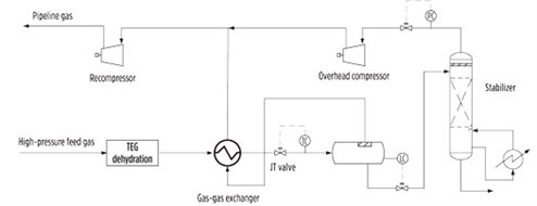
Exchanger background. Gas-gas exchangers in gas treatment processes (FIG. 1) are usually the largest exchanger in an offshore plant, with special design criteria. In this article, the possibility of replacing conventional S&T exchangers with PSHEs is reviewed, and the advantages in this application are evaluated.
 |
|
FIG. 1. Process flow for a gas-gas exchanger in a gas treatment facility.1 |
Due to the risk of hydrate formation in gas-gas exchangers, the design of S&T exchangers are required to meet certain criteria, which goes back to work done by P. W. Knight in 1975.2 The satisfactory feedback from practice encourages designers to follow Knight’s recommendations. Further studies by HTRI have demonstrated similar criteria.3
As per Knight’s recommendation, three parameters play a crucial role in sizing a gas-gas exchanger:
• Maximum tube-side velocity (to prevent foaming and formation of unstable emulsion)
• Minimum tube-side velocity (to prevent hydrate formation)
• Maximum tube length per shell based on selected tube size
These three parameters determine the size and number of S&T exchangers. It is clear that the maximum gas velocity influences achievable heat transfer coefficient, while minimum velocity and maximum tube length determine the number of shells in series. To minimize the risk of separation, it is normal to select one tube pass.
The minimum velocity limit is recommended to prevent stratification inside tubes. This limit is usually easy to observe for design flow, but very difficult to adhere to during turndown conditions. To overcome the low velocity issue in turndown, a recycle line from the compressor discharge to the exchanger inlet has been considered by some designers to boost the velocity in turndown conditions and in late-life scenarios. This modification requires additional piping and creates energy losses.
Due to the smaller channel size, the corrugated plate and the flow direction constantly breaking up the boundary layer, the chance of stratification is unlikely with PSHE. Turndown can be handled without the additional recycle line, which reduces piping requirements and power consumption.
As per common practice, minimum approach temperature for an S&T exchanger should not be less than 5°C (preferably 8°C), while it can be as low as 2°C for the PSHE. This means lower compressor power consumption, which results in considerable savings of long-term operation costs.
Lighter equipment with a smaller footprint is always a challenging activity in offshore platform design. The following example demonstrates significant savings achieved by replacing an S&T exchanger with a PSHE.
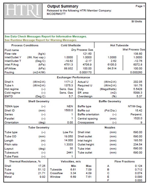
Case study: Exchanger design comparison. The design of the S&T calculation is shown in FIG. 2; the design includes the highest velocity possible to maintain the minimum required velocity in turndown condition. This design also boosts the tube-side heat transfer coefficient, which is the main resistance.
 |
|
FIG. 2. HTRI result for S&T exchanger design. |
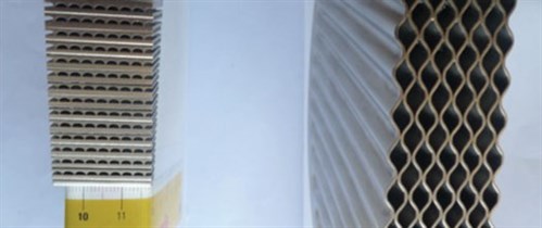
Compact exchangers. In recent years, increased attention on environmental and economic sustainability has led many end-users to review the possibility of replacing very large S&T exchangers with more compact plate-type exchangers. In this application for a gas-gas exchanger, which includes high design pressure, the printed circuit heat exchanger (PCHE) and the PSHE are considered to be the most appropriate alternatives (FIG. 3).
 |
|
FIG. 3. Channel-size PCHE (left) vs. PSHE (right). |
In the authors’ opinion, the PSHE appears to be the more attractive choice from the economic and maintenance points of view. The PSHE has larger channels and easy access to the plate pack. Feed gas entering the exchanger is usually clean because of upstream separation and filtration; however, fouling due to fine sand carryover has been reported.
PSHE construction. The construction of a PSHE is shown in FIG. 4. It essentially consists of a cylindrical plate pack within a round shell. The shell diameters range from 360 mm–1,600 mm. The plate pack is cylindrical, with circular plates of 0.8-mm thickness (depending on the design pressure and temperature), pressed with a pattern approximately 3 mm deep. The resulting heat exchange area is approximately 300 m2/m3—more than three times greater than an S&T type. As the U-value for a plate-type heat exchanger is more than twice that achieved in an S&T exchanger, the physical size is reduced by a factor of six or more.
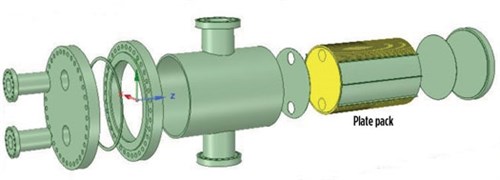 |
| FIG. 4. PSHE exchanger construction. |
The plate pack is held between circular, thick-walled plates. The plates are pressed from 316 grade stainless steel or higher, with accurate spacing obtained by the high points on adjacent ribbed plates. Alternate plates are welded at the plate-side ports to create “shell-side” passages, which are open to the annulus formed between the plate pack and the shell. The “plate-side” passages are connected by inlet and outlet headers through holes at the top and bottom of the plates, and the shell side is sealed with a circumferential weld around the rim. The diameter of these connectors, and of the plate-side connections on the front of the shell, are geometrically limited to limit the loss of the available plate area. The effective plate area between these connections is approximately two-thirds of the total circular plate area.
Reliability and maintenance. High-quality welding, plus accordion-like construction, makes the PSHE suitable for the larger temperature gradients experienced in startup, shutdown and process upsets.
The plate packs also have been tested for thermal transients, a common concern with all heat exchangers during startup, shutdown and process upsets. Thermal cycling has been conducted between ambient and –168°C, at 80 barg, where an excess of 8,000 cycles was achieved before failure occurred. Then, 36,000 cycles were performed between ambient and 100°C, at which point the test was stopped and a burst was performed. The worn-in plate pack achieved the same results as a new plate pack.
PSHEs have been successfully used in many upstream, downstream, single-phase, condensing and boiling applications. Although the PSHE shell side is accessible for mechanical cleaning just like bloc-type exchangers, PSHEs are not recommended for applications with severe fouling tendency, where frequent mechanical cleaning is anticipated on the plate side.
Flow distribution. Shell-side flow distribution in a cross-flow arrangement is always a concern. Maldistribution due to flow bypass from the inlet to the outlet, which is seen in “X” type S&T exchangers, is minimal or less likely in a PSHE. Small channels of plate pack result in a reasonable pressure drop and, consequently, even flow distribution.
HTRI performed an extensive study of flow distribution in 2019.4 The result is very satisfactory; channel-to-channel flow distribution was uniform for both the plate side and shell side in the example. Multiple inlets and outlets and reasonable pressure drop over the plate pack minimize the risk of shell-side maldistribution.
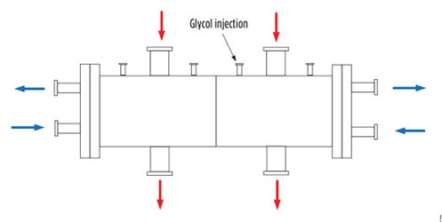
PSHE design for gas-gas exchanger. The authors’ recommended PSHE is shown in FIG. 5. Wet process gas (feed) is located on the shell side, and dry process gas (from the separator) is on the plate side. Glycol injection to the feed, which can be done in upstream pipe or directly inside the exchanger, helps prevent hydrate formation.
 |
|
FIG. 5. PSHE for a gas-gas exchanger. |
The authors offer several recommendations for designing a gas-gas exchanger as a PSHE:
- Maximum channel velocity is limited, as per Knight’s recommendation.
- Minimum channel velocity is of minor concern, since the chance of stratification is nil.
- Glycol injection can be performed within the exchanger or at the inlet piping prior to the exchanger. A CFD analysis might be needed as further study to ensure even distribution of glycol over the entire plate pack.
Recommendations. Compactness and reliability make PSHEs a suitable candidate for many non-severe fouling applications in onshore and offshore plants. It is a good fit in process and utility facilities, and can be used for debottlenecking and revamp by directly replacing an existing tube bundle with a plate pack.
Large, conventional S&T gas-gas exchangers in gas treatment facilities can be replaced with compact PSHEs, resulting in smaller footprint and a better economic and technical solution (Table 1). GP
LITERATURE CITED
- Mokhatab, S., A. Poe and J. Mak, Handbook of Natural Gas Transmission and Processing, 4th Ed., Gulf Professional Publishing, October 2018.
- Knight, W. P., “Plant operating data improve heat exchanger design,” Hydrocarbon Processing, Vol. 54, Iss. 5, 1975.
- Nangia, K. K., J. W. Palen and J. Taborek, “Field data and performance analysis for gas-gas exchanger with glycol injection,” HTRI Report STS-1, 1972.
- Farrell, K., “CFD simulation of plate and shell heat exchanger,” HTRI Report PHE-22, 2019.
 |
ROBERT BROAD is Business Development Manager–Systems at API Heat Transfer. He is a chartered chemical engineer, a Fellow of the Institution of Chemical Engineers and a member of both the International Register of Professional Engineers and the European Federation of National Engineering Associations. Mr. Broad has worked for more than
20 yr with compact heat exchangers, striving to use technology to reduce energy usage. He holds an MBA degree from Henley Management College in the UK.
 |
ABDOLLAH BAYATI is Heat Transfer Subject Matter Expert at McDermott. He has more than 20 yr of experience in fabrication, thermal and mechanical design of heat exchangers for the oil and gas industry, both onshore and offshore. His journey through fabrication to design, along with academic study, has strengthened and encouraged him to explore new opportunities for technical and economic improvement. He holds a BS degree in heat transfer and fluid dynamics and an MS degree in energy engineering.


Comments