
Obtain accurate NOX values for strategies to reduce emissions from combustion
In the process of developing low-nitrogen-oxide-emissions (NOX) combustion appliances, the request for the volume of NOX emissions from the tail flame is given in milligrams/kilowatt hour (mg/kWh) in almost all national and regional standards and related certifications. However, the instrument that measures NOX in the exhaust tail flame of the combustion reports only in ppm or mg/m3. This requires the calculation of the NOX in mg/kWh, based on the measured NOX in ppm or mg/m3 and related data for these specific combustion systems.
This article summarizes how the combustion industry presently converts ppm to mg/m3 and introduces a concept for measuring the emission rate of a combustion system. With this concept, a formula can be derived to calculate the NOX produced by combustion in mg/kWh. The combustion of methane and propane are used as examples in a demonstration of the measured ppm or mg/m3 concentration of NOX, along with the the CO2 or O2 concentration in the tail flame, to calculate the NOX emissions in mg/kWh.
This discussion explains how, when applying various methods to reduce NOX emissions from the combustion process, the traditional measurement results of NO2 content (accounting for 5%–10% of NOX) can give an estimated result. However, to obtain accurate NOX values, it is necessary to precisely measure NO value, as well as NO2 value. More accurate measurement of emissions values and amounts aids in emissions reductions for combustion, thereby helping control air pollution.
Incentives for accurate emissions measurement. Immense economic growth in China since the 1980s has resulted in significant air pollution in major cities, which poses a serious threat to public health. However, decades of hard work and investment by the municipal government have paid off, resulting in a dramatic reduction in air pollution.
The Beijing 2013–2017 Clean Air Action Plan1 is the most comprehensive and systematic pollution control program put into practice in Beijing to date. From 2013–2017, emissions of SO2, NOX, volatile organic compounds (VOCs) and particulate matter (PM2.5) decreased by 83%, 43%, 42% and 55%, respectively (FIG. 1, left). However, during the same time period, changes in major air pollutant emissions in the areas surrounding Beijing (including Tianjin, Hebei, Henan, Shandong, Shanxi and Inner Mongolia) were not as desirable (FIG. 1, right). Other areas in the country face the same problem. To clean China’s air supply, numerous issues must still be addressed; this article was written with this task in mind.
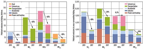 |
| FIG. 1. Changes in anthropogenic emissions of SO2, NOX, VOCs and PM2.5 in Beijing, 2013–2017 (left). Changes in major air pollutant emissions in the areas surrounding Beijing (including Tianjin, Hebei, Henan, Shandong, Shanxi and Inner Mongolia), 2013–20171 (right). |
NOX emissions caused by combustion are an important factor in the formation of air pollution and smog.2–5 NOX, which comprises mainly NO and NO2, is the general term for a group of highly reactive gases. Most nitrogen oxides are colorless and tasteless; however, in many cities or densely populated areas, the pollutant NO2 and other particles in the air often form a reddish-brown smog or haze.
When NO reacts with O2 in the air under sunlight, ozone is produced near the ground. Ground-level ozone has an adverse effect on the respiratory system, causing lung cancer and affecting agricultural production. NOX also reacts to form nitrate particles and acidic aerosols, which can cause respiratory problems. When NOX reacts with water to form nitric acid, it causes acid rain and deterioration of water quality. Additionally, acid gases and airborne particles can cause reduced visibility and reduced air quality.
Many standards, both at home and abroad, restrict NOX emissions and outline specific regulations—e.g., Beijing boiler air pollutant emissions standard DB11/139-2015,6 Chinese gas heater standard CJT113-2015,7 and European CE standard for infrared heaters BSEN 416-1.8 In all of these standards, the emissions reporting is given in mg/kWh. Many customers require manufacturers to provide NOX emissions data in mg/kWh when purchasing combustion-related appliances. For example, in Beijing, the NOX emissions from a newly built boiler cannot be greater than 100 mg/kWh.
However, almost all instruments that measure the tail flame of a burner offer a reading of NOX only in ppm or mg/m3.9 Using the measured NOX data (in ppm or mg/m3) to calculate the NOX produced by the combustion system (in mg/kWh) is an important calculation, but many relevant documents and standards offer complicated conversions or, conversely, very simple tables8,9 that do not explain the theoretical basis behind the conversions. Many standards simply do not mention the conversion method, causing confusion and difficulty for the engineering community. This article describes a simple, accurate calculation method that was derived in the process of developing low-NOX heaters.
Background on conversion of ppm to mg/m3. The engineering and academic communities have held recent discussions on the conversion of ppm to mg/m3.10 A brief overview of the conversion history follows for those readers seeking background information.
Ppm is often used to express concentration, such as mass ppm concentration or volume ppm concentration (i.e., ppmv). Ppmv is a common way of expressing gas phase concentration. Gas is miscible and, generally speaking, once equilibrium is reached the gas is homogeneous, meaning its components are evenly mixed together. In SI units, the volume for this gas is cubic meters (m3). If the gas mixture is divided into components and the concentration of one component in the gas mixture is assumed to be 1 ppm, and if the mixture is 106 m3, then the gas of this component should be 1 m3. This results in 1 m3 of a certain component, or 106 m3 for a mixture = 1 ppm.
Eqs. 1 and 2 are derived from the ideal gas law (for gases at lower pressures):11
PV = nRT (1)
PVi = niRT (2)
Here, P is the pressure (in pascal); V is the volume (m3); n is the number of moles (proportional to the number of molecules) of all components; R is a constant, called the universal gas constant, with a value of 8.3143 joules/K mole; T is the Kelvin (K) temperature; Vi is the partial volume of the gas component i; and ni is the molar number of gas component i.
Eqs. 1 and 2 can be rewritten, as shown in Eqs. 3 and 4:
V = nRT / P (3)
Vi = niRT / P (4)
Next, a certain trace gas in the mixed gas can be considered. Assuming that Vi is the volume of the trace gas and VT is the total volume of the mixed gas, both sides of the second equation are divided by VT, which gives the concentration of the trace gas that can be expressed as a volume ratio (Eq. 5):
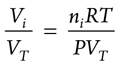 (5)
(5)
Then, xi can be used as the concentration of the trace gas component i in ppm (Eq. 6):
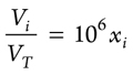 (6)
(6)
Using Xi as the mass concentration of component i in mg/m3 and assuming the molar weight of component i is Mi (g/mole) gives Eq. 7:
![]() (7)
(7)
When the low index i in these equations is neglected, Eqs. 8 and 9 result:
X = x(MP ÷ RT) × 103 mg/m3 (8)
x = X(RT ÷ MP) × 10–3 ppm (9)
Note that the concentration x is in ppm, the unit of concentration X is in mg/m3, and M is the molecular weight of the trace gas concerned (g/mole). Eqs. 8 and 9 have been generally accepted by the academic and engineering communities, and literature10 describes them at constant temperature.
Simple calculation procedures are also provided on relevant websites in America and Europe. For example, on some sites,12,13 the only required inputs are the value of the concentration x or X of a certain gas at atmospheric pressure and 25°C, along with the molecular weight of the gas. The program will immediately give the value of X or x under the corresponding conditions. In addition to the calculation,12,13 users can change the gas temperature and pressure inputs.14 The molecular weight of NO2 is 46.01 g, and the molecular weight of NO is 30.01 g; therefore, at a temperature of 20°C (293.15 K) and 1 atm, 1 ppm NO2 = 1.91 mg/m3, and 1 ppm NO = 1.25 mg/m3.
In the general combustion system, NO2 in tail flame accounts for approximately 5%–10% of NOX and NO accounts for about 90%–95%.15–18 When NO2 accounts for 10% of NOX, the average molecular weight of NOX can be calculated as M = 31.61. Under the same temperature and pressure conditions as the previous calculation, for NOX, 1 ppm = 1.29 mg/m3.
Calculation of NOX in mg/kWh for a combustion system. For a combustion system, the NOX concentration in the tail flame can be measured in ppm or mg/m3. However, the NOX emission in mg/kWh dictates how many mg of NOX are produced in a combustion system when it releases 1 kW in 1 hr. This means that NOX in mg/kWh is not only related to the NOX concentration in the tail flame, but also to the volume flowrate of the tail flame and the power produced by the combustion system.
The emission rate, E, of pollutants like NOX from a combustion system must first be defined. A combustion system is used to generate certain power or heat, thereby producing pollutants. The higher the power is generated by the system, the more pollutants are produced. Since all pollutants are discharged to air through the tail flame, the total mass flowrates of the pollutants can be calculated from the volume mass concentration of pollutants, mg/m3, and the volume flowrate of the tail flame.
E can be defined for a certain pollutant as the total mass flowrate for this pollutant in the tail flame, divided by the power generated by the combustion system. This E is listed in mg/kWh. In this article, E is used for emission of NOX, but it also can be used for emission of other pollutants, such as CO, SO2, SO3, etc.
Now the volume flowrate of the tail flame of a combustion system can be calculated. For the sake of simplicity, it is assumed that the concentrations of CO, NO, NO2, SO2, etc. in the combustion products are negligible compared to the concentrations of O2, CO2, H2O and N2. At the same time, it is assumed that there is no water vapor condensation, at least at the measurement point in the tail flame generated by the combustion system. Based on the authors’ many years of experience in the research and development of various types of heaters in the U.S. and China, these two assumptions should be valid for general combustion systems, such as infrared heaters, unitary heaters, home heaters, etc.
In air, the composition of O2 is 20.95%, while N2, Ar and other elements make up 79.05% in volume.16 If the volume flowrate of O2 is 1 for a combustion system, then the ratio of the volume flowrate of N2, Ar, etc. to the volume flowrate of O2 is 79.05 ÷ 20.95 = 3.77. Since gas components like Ar do not participate in the reaction, for the sake of brevity, only N2 is used to represent these components.
Consider the combustion of methane (Eq. 10):
CH4 + 2O2 = CO2 + 2H2O (10)
If the reaction or combustion occurs in air, then Eq. 11 can be used:
CH4 + 2(O2 + 3.77 N2) = CO2 + 2H2O + 7.54 N2 (11)
If Va represents the volume rate of CH4 consumption, then when the reaction product is cooled to normal temperature (assuming that the water vapor is not condensed at this time), the volume rate of the tail flame generated will be Va + 2Va + 7.54Va = 10.54Va. According to combustion theory,18 to avoid significant production of CO and carbon, there should be a certain excess of O2 in combustion systems. Considering this, the reaction formula in Eq. 11 can be written as shown in Eq. 12:
CH4 + (2 + y)(O2 + 3.77N2) = CO2 + 2H2O + 7.54N2 + y(O2 + 3.77N2) (12)
It is assumed that y(O2 + 3.77N2) is O2 and corresponding N2 in the excess air. If Va is the rate at which the volume of fuel gas CH4 is consumed, then the volume rate at which the reactants disappear and the volume rate of the products generated in the tail flame (when cooled to room temperature) can be calculated as shown in Eq. 13:
Va + 2(Va + 3.77Va) + y(Va + 3.77Va) and
Va + 2Va + 7.54Va + y(Va + 3.77Va) (13)
Therefore, the total flow of the tail flame produced by the combustion system will be (10.54 + 4.77y)Va.
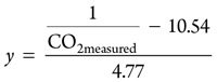
The y in Eqs. 12 and 13 can be obtained from the concentration of CO2 measured in the tail flame or the concentration of O2 measured. First, the measured CO2 concentration is measured, as shown in Eq. 14:
![]() (14)
(14)
The result is applied to Eq. 15:
 (15)
(15)
In this way, the volumetric flow of the tail flame can be represented as shown in Eq. 16:
Volume flowrate of the tail flame = 10.54Va + 4.77yVa = (1 / CO2measured)Va (16)
The power of the combustion system is generated by the consumption of CH4 at a specified flowrate (Va) and heat of combustion (HV), with the power of combustion = HV × Va. Since the mass emission rate of NOX is X, Eq. 17 is used to calculate E:
E = (Volume mass concentration of emission
of NOX × Volume flow of tail flame) /
Power of combustion system (17)
Substituting Eq. 16 and the power of combustion (HV × Va) into the formula results in Eq. 18:
E = X / (CO2measured × HV) (18)
Using the same procedure, from the measured O2 concentration (O2measured), E can be found, as shown in Eq. 19:
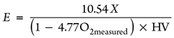 (19)
(19)
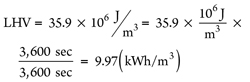
In Eq. 19, HV can be the low-combustion value (LHV) of CH4 or the high combustion value (HHV) of CH4, which is determined by the condensation of water vapor in the tail flame. The authors suggest using the LHV because it is assumed that the measurement is conducted before the water condensation,19 resulting in Eq. 20:
 (20)
(20)
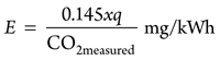
It is known that 1 hr = 3,600 sec, and 1 joule/sec = 1 W. If pressure is assumed at 1 atm and temperature is assumed at 20°C (293K), and if X = 1.25 qx mg/m3 is used, then Eqs. 21 and 22 can be calculated:
E = (0.125x)q ÷ CO2measured mg/kWh (21)![]() (22)
(22)
Here, q = MNOx ÷ MNO.
For propane (C3H8) combustion, the reaction shown in Eq. 23 occurs:
C3H8 + 5O2 = 3CO2 + 4H2O (23)
If the reaction or combustion occurs in air, then the reaction shown in Eq. 24 occurs:
C3H8 + 5(O2 + 3.77N2) = 3CO2 + 4H2O + 18.85N2 (24)
Using the same procedure as that for methane and taking the LHV of propane,19 LHV = 25.9kWh, Eqs. 25 and 26 are calculated as follows:
 (25)
(25)
E = 1.25xq[1 + 4.77O2measured / (1 – 4.77O2measured)] (26)
Here, q = MNOx ÷ MNO.
In recent years, to eliminate emissions of NOX to the environment, countries around the world have been developing low-NOX combustion technologies.4,5,20,21,22 NOX emissions reduction is important for decreasing the level of NOX released into the atmosphere by combustion activities. When NOX reduction strategies are used, the ratio of NO to NO2 may change, and so the traditional calculation of NO2 content accounting for 5% of NOX can no longer be used.
At present, the value of NO2 can be even greater than 50% of the total NOX emission. In this scenario, it is important not only to accurately measure the value of NO, but also to accurately measure the amount of NO2. Additionally, since NO2 is very soluble in water, if condensation of water vapor occurs in the exhaust smoke, as much as 50% of NO2 will be dissolved into the condensed water from the gas phase, which greatly affects the reading. Therefore, it is necessary to ensure that water vapor does not condense during the measurement.
Takeaway. This article summarizes the conversion method between ppm and mg/m3 presently used in the engineering world. It also explains the development of a method to calculate NOX in mg/kWh from combustion systems that use methane or propane as fuel. This method can be used to calculate emissions of other pollutants, such as CO and SO2. GP
LITERATURE CITED
- United Nations, “A review of 20 years’ air pollution control in Beijing,” UN Environment Programme, March 9, 2019, online: https://www.unenvironment.org/resources/report/review-20-years-air-pollution-control-beijing
- Topac Inc., “Combustion Information: Emissions,” 2006, online: http://www.topac.com/combustioninfo4.html
- “Nitrogen oxides formed during combustion,” online: http://fluid.wme.pwr.wroc.pl/~spalanie/dydaktyka/combustionen/NOX/NOX_formation.pdf
- Zonhoven, R. and P. Kalinin, “Control of pollutants in flue gases and fuel gases,” Technical Report, Helsinki University of Technology, Otaniemi, Finland, April 4, 2002.
- U.S. Environmental Protection Agency (EPA), Clean Air Technology Center, “Nitrogen oxide (NOX): Why and how they are controlled,” EPS Technical Bulletin, EPA-456/F-99-006R, November 1999.
- Provincial Standard/Beijing City Local Standard, “Emission standard of air pollutants for boilers,” DB11/139-2015, Beijing, China, May 2015.
- Ministry of Housing and Urban-Rural Development (MOHURD), Urban Construction Industry Standard of People’s Republic of China, “Gas bred space heaters,” CJ/T113-2015, January 2015.
- UK Standard, “Single burner gas-fired overhead radiant tube heaters for nondomestic use, Part 1: Safety,” BSEN 416-1:2009, April 2009; Updated version: BSEN 416:2019, “Gas-fired overhead radiant tube heaters and radiant tube heater systems for non-domestic use: Safety and energy efficiency,” November 2019.
- Testo, “Flue gas analysis in industry: Practical guide for emission and process measurements,” 2nd Ed., August 2004, online: http://dl.icdst.org/pdfs/files3/d3633ea5fcec7d6010dd38a8e5ef91fa.pdf
- Vincenti, W. G. and G. H. Kruger, Jr., Introduction to Physical Gas Dynamics, Wiley, June 1975.
- Chuan-Hong, L., Z. Wang-Xin, C. Wei-Tuan, L. Gui-Sheng and Z. Wen-Qiang, “Discussion on conversion between ppm and mg/m3,” Chinese Journal of Health Laboratory Technology, Vol. 13, No. 1, February 2003.
- aresok.org, “Conversion calculator: Conversion between ppm and mg/m3 at 1 atm and 25°C,” online: http://www.aresok.org/npg/nioshdbs/calc.htm
- Herramientasingenieria.com, “Engineering tools: Conversion between ppm and mg/m3 at 1 atm and 25°C,” online: http://www.herramientasingenieria.com/onlinecalc/ppm-mg_m3.php
- Markes International, “Conversion between ppm and mg/m3 at selected pressure and temperature,” online: https://markes.com/calculator
- U.S. National Council for Air and Stream Improvement, “A review of NOX emission control strategies for industrial boilers, Kraft recovery furnaces, and lime kilns,” Special Report 99-01, April 1999, online: https://p2infohouse.org/ref/51/50112.pdf
- TSI Inc., “Combustion analysis basics: An overview of measurements, methods and calculations used in combustion analysis,” 2004, online: https://tsi.com/getmedia/02417ee5-cccc-4dc7-80bc-f7f10924d20a/CA-basic-2980175?ext=.pdf
- Yang, X., X. Wang, Y. Cai and L. Wang, “NOX emission control technologies in sludge pyrolysis and combustion,” in Environmental Engineering III, Pawlowski, Dudzinska & Pawlowski, Eds., CRC Press, London, UK, 2010.
- Flagon, R. C. and J. H. Seinfeld, Fundamentals of Air Pollution Engineering, Prentice Hall, Upper Saddle River, New Jersey, 1988.
- North American Combustion Handbook, R. J. Reed, Ed., Vol. I, 3rd Ed., North American Manufacturing, September 1995.
- The Engineering ToolBox, “Gross and net heat values, common gases,” 2003, online: https://www.engineeringtoolbox.com/gross-net-heating-values-d_420.html
- Baukal, C. E., Jr., Industrial Combustion Pollution and Control, CRC Press, October 15, 2003.
- Baukal, C. E., Jr., The John Zink Hamworthy Combustion Handbook, Vols. 1–3, 2nd Ed., CRC Press, November 12, 2013.
 |
GY ZHAO was Technical Manager of Sunree Technology Development Co. Ltd. in Dalian, China from 2015–2020, responsible for the research and development of several heaters. He also conducted research and taught graduate courses at the Institute of Mechanics, Chinese Academy of Sciences, for 22 yr, and was awarded the Second Grade of Science Progress Award by the Academy. Dr. Zhao co-authored four books in Chinese before he relocated to the U.S. in 1988. He has published more than 30 papers in both English-language and Chinese-language scientific journals. He holds a BS degree in modern mechanics from the Chinese University of Science and Technology in Beijing and a PhD degree in chemical engineering from the State University of New York in Buffalo.
 |
LING LIU has 7 yr of working experience in combustion and mechanical design. She has participated in the research and development of negative-pressure gas infrared radiant heaters, positive-pressure gas infrared radiant heaters, indirect-fired gas heaters and direct-fired gas heaters at Sunree Technology Development Co. Ltd. in Dalian, China. She holds a BS degree in building environment and equipment engineering from Southwest Jiaotong University in China.
MAO-SONG LI has 11 yr of working experience in thermodynamics, combustion and mechanical design. He formerly supervised the laboratory of Dalian Jinsanwei Technology Co. Ltd. and managed the R&D department of Sunree Technology Development Co. Ltd. During his 7 yr at Sunree, he participated in the design and testing of negative-pressure gas infrared radiant heaters, positive-pressure gas infrared radiant heaters, indirect-fired gas heaters, and direct-fired gas heaters. Mr. Li holds a BS degree from Zhengzhou Institute of Light Industry in China and an MS degree in power engineering and engineering thermophysics from Xi’an Jiaotong University in China.


Comments