
Caustic treatment design, integration and waste disposal for gas plants
Gas processing plants offer a very different landscape than the typical oil refinery, and the methods used to treat sulfur (S) compounds in the liquids must be adjusted accordingly. When it comes to caustic treatment, one of the first configuration decisions is whether to treat the C3–C10+ NGL stream in a single unit or to fractionate prior to caustic treatment. Treating the entire hydrocarbon stream may result in less equipment, but fractionating can result in better selectivity for product specifications.
Depending on the hydrocarbon source, LPG streams will have a vastly different distribution and concentration of mercaptan molecules, which require more rigorous removal methods. Some contaminants, such as H2S, CO2, and mercaptan (RSH), can be removed from the LPG stream by caustic, referred to as extraction. Other contaminants, including COS, CS2 or dimethyl sulfide (DMS), cannot be extracted from the hydrocarbon with caustic alone.
Furthermore, the C5+ condensate streams also differ from typical refinery naphtha streams. These streams can contain very high levels of mercaptan that cannot be sufficiently removed by caustic treatment. In this case, the mercaptan species must be converted to disulfides in an alkaline environment over a fixed bed of catalyst to meet pipeline specifications. This process is referred to as “sweetening” because the mercaptans are converted and the S content of the hydrocarbon does not change. Other feed impurities will affect the design of the pretreatment and metallurgy of the unit.
This article covers the most common impurities found in caustic waste streams and how they affect the design and placement of treating units in the midstream gas processing flow scheme. These caustic treating systems also generate waste streams for disposal. As regulations on caustic disposal and S oxides (SOX) emissions tighten, it is worth considering alternative options for disposal of spent caustic, disulfide oil and spent air to meet ongoing and future changes in regulations.
Caustic treatment. Midstream gas processors historically have used different technologies to remove or treat acidic impurities in liquid hydrocarbon streams.
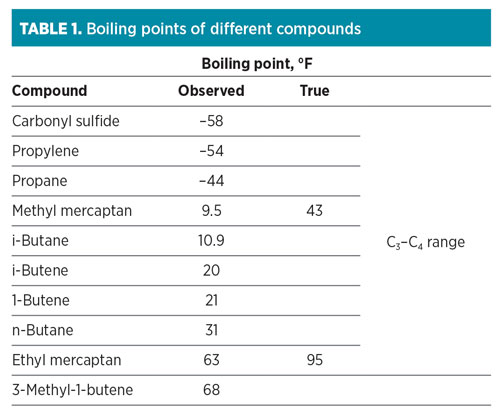
Caustic treatment remains the most economical process when removing mercaptans. Fractionation, which occurs prior to caustic treatment, cannot remove mercaptans efficiently from the hydrocarbon cuts because they form azeotropes with the hydrocarbon. TABLE 1 shows that mercaptans have higher boiling points than the hydrocarbon compounds with which they boil. As a result, the mercaptans will distribute throughout various lighter hydrocarbon fractions. Since the strong base, sodium hydroxide (NaOH or caustic), chemically reacts to remove acidic molecules H2S, CO2 and mercaptans, it can be used to remove the mercaptans or convert them, depending on the mercaptan type.
 |
Different methods of caustic treatment are used to remove contaminants from the liquid stream, meeting S specifications for pipeline mercaptan limits, downstream processing requirements, process unit feed requirements, and propylene specifications.
Alternatives in caustic treatment. Caustic treatment can be generalized into two different methods: extraction and sweetening. Extraction is where mercaptans are removed from the hydrocarbon to form low-S products. Fresh caustic can be used to remove H2S, CO2, and mercaptan from these streams with a once-through caustic contact scheme. However, once-through caustic extraction has a high fresh caustic cost and a high disposal cost. To offset this, most customers choose to catalytically regenerate the caustic, using air to convert and remove the extracted mercaptans while returning the caustic to the extractor with minimal S content. This regeneration method has a higher capital cost than once-through caustic usage but a much lower operational cost, due to the vast reduction in caustic consumption and disposal quantities.
The other type of caustic treatment is sweetening, which requires injection of air that dissolves into the hydrocarbon. The oxygen from the dissolved air and the mercaptan already present in the hydrocarbon react in the presence of the solid bed catalyst and create disulfide that remains in the liquid hydrocarbon stream. This disulfide present in the product is less corrosive than the mercaptan in the feed, despite no change in the total S. Caustic is easily separated from the hydrocarbon in the reactor vessel while spent air is separated from the hydrocarbon, either in a degassing vessel in the process or in downstream tankage, depending on the volume of spent air. Sweetening can be used to treat naphtha (C5–C12) and to produce jet fuel (C12–C20+) hydrocarbons.
Pros and cons to fractionation prior to caustic treatment. Treating the entire NGL stream without fractionation allows for minimum capital investment, but minimum efficiency.
Using one caustic concentration results in poor selectivity for mercaptan reaction or removal. In addition, contamination of caustic from pipeline chemicals can include interfering ions, acids, pipeline slip and flow enhancers, and upstream processing chemicals. Treating this variety of contaminants can increase fresh caustic consumption and spent caustic disposal. Entire-stream extraction preferentially removes light mercaptans as opposed to larger mercaptans. Heavy mercaptans remaining in the hydrocarbon would likely cause off-specification product (see FIG. 2).
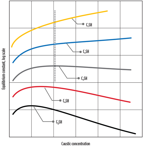 |
| FIG. 1. Mercaptan extraction curve. |
Conversely, entire-stream sweetening can better convert most of the heavy mercaptans to disulfide in the presence of lower-strength caustic. This will cause a loss of light hydrocarbon from spent air vented from the hydrocarbon. Additionally, this process would need to have large fixed-bed reactors to accommodate the liquid flow and required space velocity.
Fractionation and individual treatment of narrowly cut fractions maximizes treating efficiency. Using the most effective caustic concentration for each treating objective optimizes selectivity for mercaptan removal or conversion.
Extraction designs are extremely flexible and can be optimized for mercaptan removal from lighter feeds [C1 and C2 (gas phase) and C3 to C5 (liquid phase)] containing 2 wppm mercaptan S–20,000+ wppm mercaptan S in one or multiple tight cut extractors. This process can be designed to achieve minimum reentry of S, reducing the S to less than 5 wppm S in the product, and in some cases less than 1 wppm S. Since heavy mercaptans are not in this cut, stronger caustic can be used, which increases the efficiency of the extractor, reduces caustic circulation rates and reduces vessel sizes.
Heavier condensate feeds (C5–C20+) will contain heavier mercaptans with concentrations ranging from 20 wppm S to 2,000+ wppm S. These streams are more efficiently treated via sweetening with weaker caustic strengths to increase heavy mercaptan solubility. Since the treated hydrocarbon has low vapor pressure, minimum loss of hydrocarbon product occurs with the spent air vented from the hydrocarbon. Smaller-size fixed-bed reactors can accommodate the liquid flow at the required space velocity for the desired conversion. As a result, mercaptans are sweetened to disulfide to less than 5 wppm mercaptan S for naphtha and less than 20 wppm mercaptan S for jet fuel.
Additionally, the product naphtha can be fractionated to concentrate heavy disulfide S formed from sweetening the mercaptans in the heavy cut, leaving a sweet, saleable light cut of naphtha.
Typical and atypical impurities, and effect on design. Several common impurities, such as CO2, COS, H2S and RSR, can exist in the feed to the systems. Although it is expected that entire-stream amine treating and fractionating of the ethane cut would remove all the CO2 in the C3 and C4 cuts, CO2 has been observed in these cuts at midstream facilities to the concentration of 100 wppm–1,000 wppm. Caustic can be used to completely remove CO2 and H2S, but it is consumed irreversibly and would represent an operating cost in the range of millions of dollars.
The preferred method of treatment at these high concentrations is an amine absorber to reduce the concentration to less than 25 wppm, followed by a caustic prewash upstream of the caustic treater. COS can be removed to less than 1 wppm by pretreatment in a proprietary prewash design,a or during post-treatment with a modified caustic blend.b
Even though the typical impurities are present, atypical impurities can affect the design of a complex. These atypical impurities include oxygen, methanol, glycol, corrosion inhibitors, naphthenic acids and unusual mercaptan distributions. Various corrosion inhibitors and slip enhancers will initiate and stabilize emulsions between hydrocarbons and caustic. In addition, methanol can come from many upstream sources (e.g., dehydrators) and form emulsions with caustic. Excessive methanol quantities should be removed with a water wash prior to amine or caustic treating. Additionally, shared regeneration sections, discussed later in this article, transfer methanol from one segregated stream to another.
Glycol and other oxygenates also must be considered. These impurities can cause acid corrosion in sweetening units. Two options exist to minimize the occurrence of acid corrosion.c The first option is to construct the existing reactors from 316L stainless steel. The second option is to apply special epoxy to the carbon steel and concrete surfaces. This creates an epoxy layer to protect the carbon steel of the reactor. However, the epoxy will need to be replaced at every turnaround of the unit.
Integration of caustic treating with the complex. Different options exist to integrate caustic treating units into a grassroots or existing plant. One configuration may treat the entire LPG stream with caustic extraction for use as power plant fuel, low-S motor fuels, or sales to other processors.
One example, shown in FIG. 2, places a C3 extraction process unit just after the depropanizer, thereby producing low-S propane required by a dehydrogenation process to produce propylene. Butanes from the debutanizer are treated in the C4 extraction process unit, which creates a low-S C4 cut for further fractionation by the deisobutanizer to generate low-S isobutane and n-butane. The caustic is rich in mercaptides from both the C3 and C4 extraction systems and are sent to a common regeneration system to reduce capital cost.
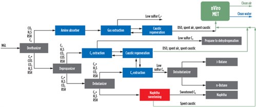 |
| FIG. 2. An example integration of caustic treatment into an existing plant. |
Ultra-low-S specifications of less than 2 wppm total S can be reached in the extraction products by installation of a newly designed disulfide scrubber to drastically reduce the disulfide present in the regenerated caustic. The disulfide scrubberd virtually eliminates reentry of S into the product streams by counter-currently contacting the caustic stream with a hydrocarbon stream, reducing the total product S by more than 95% over a design without it.
The bottoms of the debutanizer can be processed through a naphtha sweetening process.e This process treats C5–C12+ to less than 5 wppm mercaptan S with minimum alkalinity requirements, which can then be used to dilute bitumen when creating synthetic crudes.
Another option after sweetening is fractionating the naphtha to produce a low-S C5 and C6 material.f Fractionating out the light C5 and C6 material concentrates the heavy disulfides created during the sweetening process in the bottoms product.
Methods for disposal of waste caustic and spent air. Caustic prewashing is necessary to completely remove the residual H2S and CO2 from the feed hydrocarbon. It is used upstream of the extraction process so that the feed is free of H2S and CO2, which creates an S-laden caustic stream that must be disposed of.
During the extraction process, mercaptan transfers from oil to the aqueous caustic phase. The generated sodium mercaptide remains in the caustic, which is then separated from the hydrocarbon phase. The sodium mercaptide is then catalytically oxidized with injected air at almost ambient conditions to produce disulfide, which separates from the caustic. This regeneration process creates an S-laden spent air stream, caustic stream and disulfide oil stream that must be disposed of (FIG. 3). The naphtha sweetening process also makes use of caustic and will produce a waste caustic stream that must be disposed of.
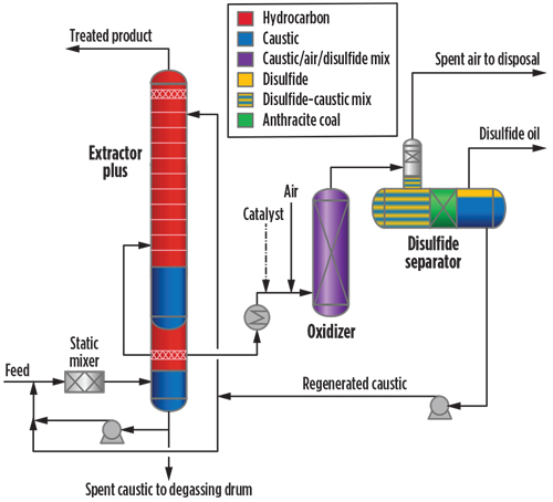 |
| FIG. 3. Sulfur streams are spent air to disposal, disposal oil and spent caustic to degassing drum. |
After the extraction and/or sweetening processes have been completed, several methods exist to dispose of the effluent waste caustic, disulfide oil and spent air from the treating units. Each of these effluent streams have different disposal methods, depending on acceptable environmental regulations. As emission regulations continue to tighten, the disposal of these effluent streams will come under greater scrutiny. Minimizing environmental impact through use of greener technology alternatives is becoming the best practice to process these streams.
Typical disposal methods for spent caustic include:
- Paper mills: These mills use sulfidic caustic in the manufacture of caustic. If the midstream facility is near a paper mill, a regeneration section may not even be necessary, since the paper mill will likely pay the fresh caustic cost to take the caustic.
- Deep well: The waste caustic is pumped back into a well belowground. This is the least expensive alternative; however, consent decrees allowing this practice are expiring, and environmental agencies are unlikely to renew them.
- Wet air oxidation methods: Sulfidic caustic catalytically converts to salts in a reactor while reducing chemical oxygen demand (COD) and biochemical oxygen demand (BOD) by 50%–95%. Various installation costs and recurring operating and catalyst costs are involved. Units are difficult to operate due to salting out and reactor bed plugging.
- Acid neutralization: A mineral or strong organic acid is used to neutralize the caustic. H2S, mercaptans and other acid gases evolved from the solution are either incinerated or captured by other technologies, creating more disposal issues.
- Waste hauler: A special waste hauler picks up the caustic from the site and disposes of it; the cost could exceed millions of dollars per year.
- Green disposal unit: Generates a 100% environmentally compliant liquid or solid streamg (FIG. 3).
The current disposal methods for disulfide oil include:
- Deep well: See previous section
- Combination with sweetened naphtha: The combined stream can be sold as bitumen diluent
- Waste hauler: See previous section
- Incineration in a combustor: SOX and other consent-decree gases are generated
- Green disposal unit: Generates a 100% environmentally compliant liquid or solid stream (FIG. 3).
The current disposal method for spent air includes:
- Vent to atmosphere: Typically needs activated carbon canisters or special consent decrees for the strong, objectionable disulfide and mercaptan smell
- Incineration in a combustor: See above
- Green disposal unit: Generates a 100% environmentally compliant liquid or solid stream (FIG. 3).
Takeaway. Caustic treatment is an important part of gas processing operations to combat impurities to prevent corrosion and to meet a variety of regulations. Many impurities need to be considered when designing a treatment plan, including the boiling points of different compounds, as well as chemical reactions.
Extraction and sweetening processes are solutions to caustic treatment that can be designed for greenfield installations and retrofitted into existing plants to maximize efficiency and provide a cleaner feed to further downstream processes. Each customer is faced with specific constraints, and licensors can provide guidance on the tradeoffs between entire-stream or partial-stream treating to meet CAPEX and OPEX objectives.
Additionally, these treating processes can be combined with the state-of-the-art effluent disposal technology to provide a greener, more-flexible effluent treatment solution to meet the processor’s needs and regulation requirements. GP
NOTES
a UOP’s Enhanced Prewash design
b UOP’s post-treatment COS removal section
c Observed and diagnosed by UOP at various midstream facilities
d UOP disulfide scrubber
e UOP Minalk sweetening unit
f UOP SweetFrac
g UOP Callidus’ nViro Met
 |
JESSY TRUCKO is Principal Technology Specialist in the Treating Technical Services Group at Honeywell UOP. He has been with Honeywell UOP for more than 20 yr. During his time in UOP’s Development Group, he advanced the company’s alkylene and FCC technologies. Mr. Trucko has been involved with Merox as a Project Engineer in the Gas Processing Engineering Department and as a Treating Technical Service Specialist for the past 13 yr. During this time, he designed individual units and complexes. He has also innovated multiple improvements to the Merox design, some of which are trade secrets and others which have been awarded patent. Mr. Trucko holds a BS degree from the University of Illinois at Chicago, is a Six Sigma Black Belt and holds seven patents.
 |
JON TERTEL is Senior Offering Manager for Alkylation and Merox at UOP LLC, a Honeywell Company. Over the past 29 yr, he has performed assignments with increasing scope of responsibility in field operating services, engineering, management, technology development and business associated with a range of key UOP refining, petrochemical and gas purification technologies. Mr. Tertel obtained his BS degree in chemical engineering from the University of Wisconsin at Madison and holds more than 25 U.S. patents.


Comments