
Safely design brazed aluminum heat exchangers to avoid thermal shock
Although brazed aluminum heat exchangers (BAHEs) are designed per American Society of Mechanical Engineers (ASME) Pressure Vessel Code Section 8, they are still very sensitive to temperature fluctuations. The corrugated aluminum plates are tightly brazed with one another, and they expand and contract together. This expansion/contraction between the corrugated plates or other parts of the BAHE can be disproportionate if the rate of temperature change is high, resulting in metal fatigue and possible cracks or leaks.
The material will be slightly deformed due to these external forces. If these forces are lower than its yield strength, then the material will return to its original shape as the forces are removed. However, if these low forces due to temperature changes are repeated regularly, then the material can be thermally fatigued and cause fatigue cracking. Process fluid can leak to atmosphere or adjacent layers from these cracks.
If the brazing joints between the fins and cap sheet fail due to thermal fatigue, it will increase the stresses on adjacent joints and cause a possible chain failure on the fin matrix. This chain reaction can result in sudden rupture at an operating pressure that is less than the design pressure. It means that the BAHE passes must be depressurized by removing the process fluid, which would help reduce the stresses.
Further dialogue between designers, manufacturers and operators is necessary to evaluate the impact of cyclic temperature fluctuations, which depend on the size and configuration of the BAHE.
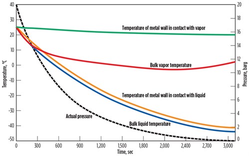
The Brazed Aluminum Plate Fin Heat Exchanger Manufacturers’ Association (ALPEMA) recommends not to exceed the rate of temperature change across any heat exchanger pass beyond 2°C/min or 60°C/hr, as high thermal stresses can damage the aluminum cores.1 If stream temperature changes are cyclic or recurring, then the allowable rate of temperature must be less than 1°C/min to prevent thermal fatigue.
Some operators do not strictly follow these limits during heating or cooling operations (e.g., startup, shutdown and emergency depressurizing). Generally, the ALPEMA members allow up to 5°C/min for these not-so-frequent-scenarios. If a BAHE experiences high-temperature changes for a longer period of time, then the manufacturer or maintenance experts should be consulted for inspection and possible leak tests or maintenance.
For example, on June 27, 2016, Enterprise Products’ gas plant in Pascagoula, Mississippi saw the failure of a BAHE, which resulted in a major loss of containment that shut down the plant for 6 mos. This article suggests how to safely design and operate BAHEs to avoid thermal shock and fatigue. This will also help remove the “black box” tag from these heat exchangers.
Should BAHEs be depressurized? Two practices are mostly followed for depressurizing of BAHE passes in case of an emergency situation, e.g., fire and gas detection:
- Provide shutdown valves at the inlet/outlet of each pass and keep the exchanger under pressure
- Depressurize in a controlled manner to remove the inventory.
Some companies decide not to depressurize the BAHE and leave the liquid/vapor inventory inside the cores in case of emergency, including confirmed fire and gas detection. With this approach, automatic emergency shutdown valves are provided at the inlet and outlet of all passes and are forced closed in case of external fire or manual shutdown by an operator. These valves should have a tight shutoff and be fireproof to sustain heat for at least 4 hr.
After the emergency is over and the main equipment has been depressurized, opening the isolation valve to restart the passes can be challenging, as it will mix the warm and cold fluids at either side of the valve. This will result in a high rate of temperature change. It may be advisable to depressurize the passes at a slow pace, using a vent connection equipped with a restriction orifice. The main isolation valves can be opened when both upstream and downstream fluids achieve similar temperatures. Placing a fast-closing shutdown valve downstream of the cold box can result in a sudden surge on the BAHE pass. Surge analysis will be required to ensure the mechanical integrity.
The other, preferred option is to depressurize all the passes in case of a confirmed fire, as a large fire can damage the external carbon steel box and reach the ASME Section 8 designed BAHE cores. Following this philosophy will bring each pass under a particular “depressurizing section” between the isolation valves equipped with a blowdown valve and a restriction orifice. Detailed dynamic simulations are needed for this option to ensure that the rate of temperature change during depressurizing remains within the allowable limit.
Temperature sensitivity of liquids. Liquid passes of a BAHE are more sensitive to temperature changes due to their higher heat capacity than vapors. Although not clearly specified by ALPEMA, API 662 or other standards/practices, the 2°C/min criteria could be applied on the bulk fluid or the actual metal temperatures, although these are entirely different approaches. Misconception can result in sub-optimal design of BAHE facilities.
In an ideal world considering isentropic depressurizing, lighter gaseous components cool down to lower temperatures, compared to liquids, due to the lower heat capacity of vapor. For example, pure C2, C3 and C4 are isentropically depressurized from 60 barg and 30°C to atmospheric pressure, and the final temperatures are found to be –89°C, –42°C and –12°C, respectively. If the pressure of these pure components is reduced in fixed time (e.g., 15 min), then the dT/dt of bulk C2 would be greater than the heavier hydrocarbons.
This approach, however, is not conservative for BAHE metal, as the metal mass in direct contact with liquid cools to a lower temperature than the metal mass in direct contact with vapors. This makes liquid handling of BAHE passes more sensitive and fragile than those handling vapors. This approach was demonstrated for pressure vessels2,3 and is elaborated in this article for BAHE. Recording the actual metal temperature provides actual effect for the aluminum metal, particularly for the liquid streams at the lower end of the BAHE.
As a case study for this understanding, a gas mixture (80 mol% methane, 10 mol% ethane, 10 mol% propane) is depressurized from 60 barg and 30°C to atmospheric pressure. The actual temperatures of bulk fluids and metal are presented in FIG. 1. The rate of temperature change is presented in TABLE 1. The wall temperature in direct contact with liquids was found to be much lower compared to the wall temperature in direct contact with vapors.
 |
| FIG. 1. Effect of pressure reduction on a gas of 80 mol% methane, 10 mol% ethane, 10 mol% propane. |
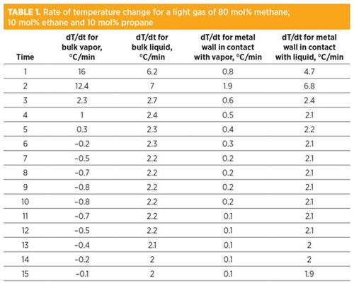 |
As the heat capacity of the gases is lower than that of the liquids, the temperature of the gases is reduced faster than the temperature of the liquids at the beginning of the depressurizing process, which means that the dT/dt for gases is higher than that of the liquids. After a short time, the temperature of the gases starts to increase due to heat intake from metal mass. The temperature of metal in contact with gas is slightly reduced. As the thermal conductivity of gas is low, the metal in direct contact with gas does not cool down to match the gas temperature. The temperature difference between the metal and bulk gas is found to be quite high (> 20°C).
Liquid temperature is consistently reduced during the depressurizing process. Liquid also takes in heat from metal; however, due to the higher heat capacity of liquids, the temperature of metal in direct contact with liquid is also reduced and liquid temperature does not increase. As thermal conductivity of liquid is higher than gas, the liquid portion of fluid extracts heat from vessel walls and cools the metal. The temperature difference between the metal and bulk liquid is quite low (< 5°C). The overall temperature of the liquids is lower than that of the gases because gases will regain temperature from metal walls during depressurizing, resulting in higher final temperatures.
As previously explained, the rate of temperature change (dT/dt) for the bulk gas is higher than for the bulk liquid due to a difference in heat capacity. The rate of temperature change of the metal is much higher for the metal wall in direct contact with liquid, in comparison with the metal wall in direct contact with vapor, due to a difference in thermal conductivity and heat capacity. Note: The rate of temperature change of the metal should be compared with the maximum allowable 2°C/min criteria instead of bulk fluid temperatures, as quick changes in metal temperature can cause thermal stresses and permanent physical damage to a BAHE.
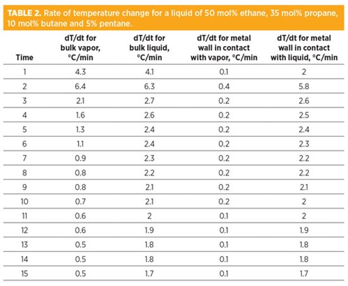
FIG. 2 shows the results of another sensitivity analysis for a heavier liquid of 50 mol% ethane, 35 mol% propane, 10 mol% butane and 5% pentane. Similar to the analysis for the light gas, the metal temperature in direct contact with the liquid experienced a higher temperature drop compared to the metal in direct contact with the gas.
 |
| FIG. 2. Effect of pressure reduction on liquid of 50 mol% ethane, 35 mol% propane, 10 mol% butane and 5% pentane. |
Similar to the analysis for the light gas, the rate of temperature change for metal in direct contact with the liquid is higher than the metal in direct contact with the gas (TABLE 2). The startup, shutdown and depressurizing of the liquid systems must be analyzed very carefully to avoid high thermal stresses.
 |
The vapor–liquid ratio in the BAHE passes can change during an upset condition due to the boiling or condensation process, leading to variable and localized temperature changes. The variable vapor–liquid fraction in the BAHE can also thermally stress the BAHE, even when temperature differences at the inlet and outlet remain low. If slugs form in the vertical BAHE passes, then the heat transfer will vary due to different heat capacity/thermal conductivity of liquid and vapors. This can result in higher temperature changes and oscillation of metal particles. The operator may wish to drain liquid from some passes of the BAHE during upset conditions such as startup or shutdown, in an effort to control the heat transfer. This will help remove the liquid from the cold box quickly.
Depressurizing valve at cooler end. It is also important to provide a depressurizing valve at the cooler end of the BAHE pass so that the cold stream can be further cooled with respect to pressure reduction, which means the rate of temperature change across the BAHE will be lower. Conversely, if a depressurizing valve is provided at the hot side, then opening of the valve will push cold liquid toward it through the cold box pass, resulting in high temperature change across the cold box pass.
The location of the depressurizing valve can allow the use of carbon steel material instead of stainless steel, resulting in considerable cost reduction in piping, valves and fittings. For example, the piping at the cold side of the BAHE pass is stainless steel, and the warm side of the same pass is carbon steel. If tapping of the depressurizing valve happens at the cold, stainless steel side, then the low temperature during depressurizing may not require a change from carbon steel to stainless steel, as the warm fluid will migrate through the blowdown valve during depressurizing and the temperature at the warm side can remain within the carbon steel temperature limit.
In another case, if the tapping of the depressurizing valve is placed on the warm carbon steel side, then the temperature of this side will be reduced during depressurizing. If the depressurizing temperature is less than the carbon steel limit, then the stainless steel material should be used.
The settle-out temperature of the entire section at the upstream and downstream of the BAHE pass should also be checked for pressurized shutdown (without depressurizing) to ensure the use of the carbon steel material.
Depressurize slowly. Equipment designed as per ASME Section 8 are depressurized in case of external fire. Internal pressure is quickly reduced to keep the stresses below the rupture stress.
These equipment, including BAHE passes, are depressurized within 15 min to either 6.9 barg or to 50% of design pressure. For a high-design-pressure BAHE, it can be challenging to depressurize the passes to 6.9 barg while keeping a maximum temperature change criterion of 5°C/min.
TABLE 3 show data for a case study for the depressurization of two BAHEs comprising high and low design pressure passes. It compares the rate of temperature change (dT/dt) with regard to the design pressure and whether the pass should be depressurized to 6.9 barg or to 50% of design pressure.
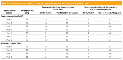 |
Once the restriction orifice is sized for the external fire case, as per TABLE 3, the rate of depressurizing for spurious depressurizing (due to false fire and gas detection or operator error) is also impacted. Note that the non-fire case (spurious depressurizing) has no time criteria.
TABLE 4 presents the rate of temperature change for spurious depressurizing from operating pressure to 6.9 barg and to 50% design pressure to reduce the temperature fluctuations. As can be seen in TABLE 4, the rate of temperature change is significantly higher than the allowable limit if the pass is depressurized very quickly—i.e., from design pressure to 6.9 barg within 15 min. This will result in higher stresses that can accumulate in the case of frequent depressurization, leading to possible leakage. Risk levels in this case are medium to high.
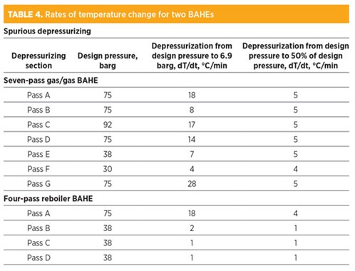 |
In the other case, the depressurizing system is designed so that the pressure is reduced from design pressure to 50% design pressure. This way, the temperature changes are within allowable stress limits and the risk level is low.
Temperature changes are also higher for high-design-pressure passes (75 barg and 92 barg) because significant moles of fluid are quickly released from high pressure due to high pressure drop across the restriction orifice.
Control valves sizing. Control valves with a larger size than required or quick response time can result in high temperature fluctuations, particularly for the high-pressure-drop valves commonly used in cryogenic plants. Inadvertent fail-open for these control valves can lead to a major upset condition for BAHE operating temperatures. Frequent failure of any of these control valves might result in accumulation of thermal stresses, which may reduce the BAHE life and cause integrity issues.
In case of very critical service, a small restriction orifice or needle valve with a removed handle can be added at the air supply/return line to restrict the fast movement of sensitive control valves. The function and location of these orifices/valves must be logged in the safety register.
Case study for control valve fail opening at BAHE. The dynamic simulation results of a sudden control valve failure at an NGL extraction facility are shown in FIG. 3. The control valve response time is 10 sec from normal 76% opening to 100%, resulting in high dT/dt across all seven passes of the BAHE under consideration. This temperature fluctuation is very high across the passes soon after the control valve failure and is as high as 23°C/min in Pass D. The impact will be diluted in time, as the other equipment and control system around the BAHE respond to reduce the impact.
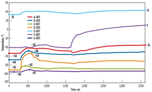 |
| FIG. 3. Temperature fluctuations across the BAHE due to control valve failure. |
If opening of FV-01 is limited to 10% above the normal opening via mechanical stopper or soft stopper in the distributed control system (DCS), then temperature fluctuations will be significantly reduced. The result of sudden control valve opening from normal 76% to a maximum of 86% is shown in FIG. 4.
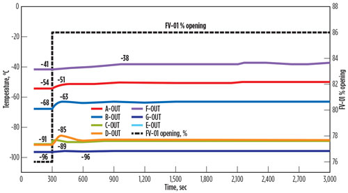 |
| FIG. 4. Temperature fluctuations across the BAHE if opening is capped. |
An inadvertent operator error can also force the control valve to a higher opening/closing percentage, resulting in high dT/dt. To avoid this issue, a slow response time can be built into the control valve’s logic.
A reverse calculation is performed to limit the dT/dt to 2°C/min by reducing the control valve response time in the DCS/programmable logic controller (PLC) control system. This slow response time will avoid quick opening of the control valve, even if the operator forces the control valve to an open position in manual control.
If the ramp-up function is slowed via DCS function, it will take 25 min to open from 76% to 100% while avoiding high dT/dt across the gas/gas heat exchanger (FIG. 5). For this sensitivity analysis, the opening time of 25 min is back-calculated by maintaining dT/dt within the limit of 2°C/min.
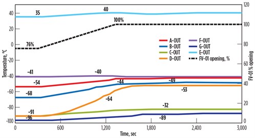 |
| FIG. 5. Temperature fluctuations across the BAHE for slow response time of control valve. |
Failure at Pascagoula plant. On June 27, 2016, Enterprise Products’ gas plant in Pascagoula, Mississippi saw the failure of a BAHE that resulted in a major loss of containment and a 6-month plant shutdown. The U.S. Chemical Safety and Hazard Investigation Board (CSB) published a case study4 of the incident that highlights some of the design and operation flaws.
The CSB investigation found that the most likely initial event was the failure of a BAHE cap sheet (a side cover plate and portions of several layers; see FIG. 6) and that this was most likely caused by thermal fatigue cracking (crack growth due to thermal cycling and excursions outside the recommended limit of 2°C/min) resulting in “accumulated thermal fatigue.”
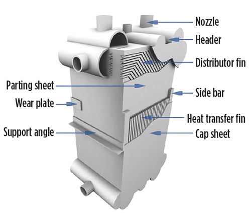 |
| FIG. 6. BAHE diagram showing cap sheet. |
Although not discussed in the report for the Pascagoula gas facility, the photographs contained in report show the following design faults:
- The BAHEs do not appear to have been installed in cold boxes/casing, which would have been filled with perlite insulation and continuously purged with nitrogen.
- Structural steel within the vicinity of the fire does not appear to have been fireproofed, and deformation is visible. The report states that the site experienced 13 different ruptures of piping and equipment during the incident.
- General insulation inside the plant does not appear to have stainless steel cladding.
The CBS has eliminated other possible causes, including over-pressurization, ice formation, thermal shock, corrosion and mercury embrittlement.
The Pascagoula plant’s BAHE failed as a result of process fluids leaking into outer layers of the exchanger due to thermal fatigue damage. These outer layers were blocked, with no relief venting, after a previous repair for thermal fatigue-induced cracking. They became over-pressurized and catastrophically ruptured. The failure of the cap sheet occurred due to several factors:
- The existence of blocked layers within the exchanger
- The development of thermal fatigue cracks in the parting sheet adjacent to the blocked layers
- The separation of at least one layer from the core of the exchanger
- The expansion of the accumulated fluid in the blocked layer due to heating
- The absence of venting or draining to allow the accumulated fluid to readily escape from the blocked layer.
Predicting thermal fatigues. ALPEMA and API 662 guidelines of 2°C/min during startup/shutdown and 1°C during cyclic operation do not provide any comparison among these temperature fluctuations, their resulting theoretical thermal stresses and actual historical conditions on BAHEs in the real world to calculate potential leakages. No guidelines are available to describe how much time above 2°C/min is allowed, or when an inspection or leak test is warranted if the exchanger has been exposed to a number of cycles above this dT/dt guideline.
Repeat thermal fatigue will eventually result in leaks. No reliable way exists to directly measure fatigue damage before it results in a leak. This is mainly due to complexities involved with the causes, such as frequency of temperature fluctuations, the duration of each cycle and the extent of temperature variations. Nevertheless, the majority of BAHEs that experience thermal stress cracking, either from high-cycle fatigue or from low-cycle thermal shock events, exhibit small leaks that can be detected and repaired in the field.5
As per API 572,6 “It is important for the owner-user and the inspector to understand that fatigue cracking is likely to cause vessel failure before detection with any non-destructive methods. Of the fatigue cycles required to produce failure, the vast majority are required to initiate cracking, and relatively few cycles are required to propagate the crack to failure.”
After the failure of the BAHE at the Pascagoula facility, the CSB calculated historical temperature fluctuations for the inlet and outlet streams.6,7,8 The data is plotted in FIG. 7. Meanwhile, FIG. 8 shows the time period for high-temperature fluctuations per unit time. Temperature fluctuations (dT/dt) are categorized into five temperature ranges, split between two graphs, to illustrate the magnitude of stream temperature changes.
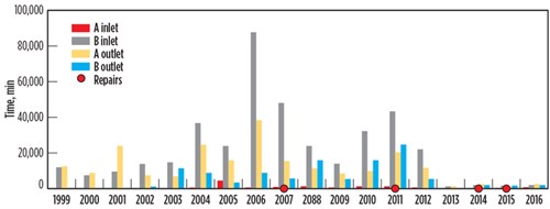 |
| FIG. 7. Historical data for the Pascagoula gas plant showing total min/yr that the temperature changes were higher than 1°C/min. The red dots indicate years of actual leakage; the leaks were later repaired.4 |
Note: The Y axis scale is different for the graphs in FIG. 7 and FIG. 8. The CSB compiled the data without filtering the startup, shutdown or upset conditions. It is also possible that these numbers were very high, as the full data is not available.4
The plot in FIG. 8 demonstrates that high dT/dt lasted a long time—sometimes even several days. This happened every year from 1999–2006, which did not result in immediate leakage; however, accumulated thermal fatigue during this time resulted in leakages in 2007, 2011, 2014 and 2015. Although these leaks were repaired, the localized repairs could not reverse the thermal fatigue accumulated on other parts of the exchanger that had not yet resulted in a leak. Literature suggests that “there is no way to reverse damage accumulation due to thermal fatigue.”5
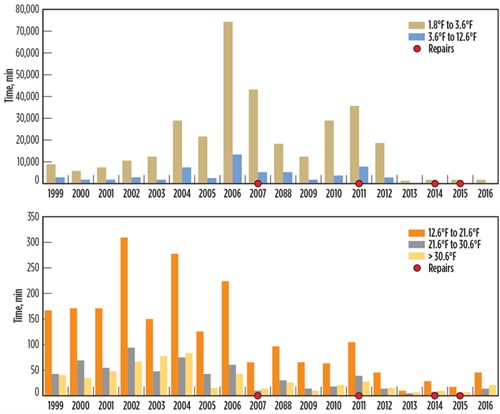 |
| FIG. 8. Historical data for the Pascagoula gas facility. |
It appears that operators were more vigilant in reducing the temperature variations after the first leak in 2007. However, the accumulated thermal stresses had already damaged various sections of the BAHE. Even small variations in temperature or pressure swings resulted in regular leaks, which resulted in the major accident in 2016. GP
LITERATURE CITED
- “The Standards Of The Brazed Aluminum Plate-Fin Heat Exchanger Manufacturers’ Association (ALPEMA),” ALPEMA, 3rd Ed., May 2012.
- Haque, M. A., et al. “Rapid depressurization of pressure vessels,” J. Loss Prev. Process Ind., Vol. 3, Iss. 1, January 1990.
- Haque, M. A., et al. “Blowdown of pressure vessels: Experimental validation of computer model and case studies,” Trans IChemE, Vol. 70, Part B.
- U.S. Chemical Safety and Hazard Investigation Board, “Case study: Loss of containments, fires, and explosions at Enterprise Products Midstream Gas Plant,” February 13, 2019, online: https://www.csb.gov/assets/1/6/final_case_study_-_enterprise.pdf
- Chart Energy & Chemicals Inc., “BAHX product bulletin,” Iss. 1, April 2016.
- API, “API Recommended Practice 572: Inspection of pressure vessels.”
- API, “API Standard 662: Plate heat exchangers for general refinery service.”
- API, “API Recommended Practice 579-1: Fitness for service,” June 2016.
 |
IRFAN HUSSAIN is Lead Process Engineer at OQ Oman. He is a Chartered Engineer (CEng), a member of MIChemE-UK and a Chartered Professional Engineer (CPEng) of MIEAust-Australia. Mr. Hussain has been working is the upstream and downstream oil and gas industries for 19 yr. He has worked with various operating and design engineering companies in the UK, Oman, Australia and Pakistan.


Comments