
Increase turbine availability and efficiency with real-world-tested filters
Gas turbines used in the onshore oil and gas industry require protection from contaminants within the inlet flow. Particles allowed to pass into the turbine can cause damage to turbine parts, reduce efficiency and even cause catastrophic failures. The challenge for operators is to find an optimum filtration solution that will handle the site conditions, which vary from installation to installation. If selection is solely based on data from tests carried out in a laboratory setting, then the filter will not necessarily perform the same way when installed in the real world.
Significant gains in turbine availability and efficiency can be achieved through the correct use of improved-efficiency air filters. The more contaminants that are allowed through to the turbine, the quicker its aerodynamic efficiency will decrease and the greater the risk of damage to the machine. Ultimately, this reduction in performance will result in reduced power output, lower system availability and reliability, and higher maintenance costs. This means the selection of filter(s) is a vital part of ensuring overall process performance. The cost of shutting down a major facility, such as an LNG train or a gas compressor station, can run into the tens of millions of dollars per day.
Environmental factors to consider: Dust and sand. If the turbine is in a dusty location, such as a desert or near a cement works, the filters must be able to handle the large volumes of airborne dust and sand without becoming blocked in a matter of days. They must also provide predictable performance and prevent sudden blockages, which would lead to an unexpected spike in differential pressure across the system and turbine shutdown.
Large volumes of dust or sand can create multiple challenges for the operator. While high-efficiency filtration media offers greater protection for the turbine, excessive volumes of dust can cause filters to block very quickly, creating a maintenance nightmare and reduced system availability. In such locations, a self-cleaning pulse system is often advised. This system periodically fires a reverse jet of air through the filters to remove dust cakes from their surfaces. The intervals for these “pulses” can be configured either by a fixed time period or based on the differential pressure (dP) across the filter. Once the dP reaches a setpoint, the system pulses until the dP drops below a set hysteresis band. This helps with long-term efficiency and reduces the amount of downtime required for filter replacement.
Moisture. If an installation is in a coastal location or in an area prone to fog or mist, the filters must be able to handle moisture along with dry contaminants. If mishandled, dust will mix with moisture to form mud that will block the filters and eventually lead to an unplanned outage of the turbine. The moisture itself can also cause problems in some types of high-efficiency filter, as the mist or fog contains tiny particles of moisture that can work their way into the media and become stuck, thereby blocking pathways for the air to pass through.
Rainfall is not an issue because the water droplets are too large to enter the filter media. Coalescers can be used to collect the tiny moisture droplets from mist or fog, bringing them together to form large water droplets that fall out of the air flow. Care should be taken with the technology selection here because, if the system captures sand and dust along with moisture, it too will become blocked. If operating in an area with high volumes of dust, a coalescer should be designed to capture moisture but deliberately allow dust to pass freely through, where it then can be handled by the media in subsequent stages of the filtration system.
Where moisture droplets or fine hydrocarbon mists are present, media selection is also a critical choice. High-efficiency expanded polytetrafluoroethylene (ePTFE) type filters use thin layers of media. This means that moisture trapped within them can lead to blockages in relatively short periods of time. A fiberglass media, on the other hand, is typically around 10 times thicker and, while still offering excellent filtration efficiency for sub-micron particles, it may be considered a better option as its thickness means that it has more pores to let air pass through, and moisture droplets will not quickly block the filter.
Salt. Particularly perilous to a gas turbine is salt, as the sodium within it can mix with the sulfur in the fuel to create an effect known as sulfidation. A chemical reaction between the sodium sulfate and high-temperature turbine metal attacks the base metal of the turbine blades, quickly eating away at the clean, smooth surfaces of the compressor turbine blades and eventually leading to catastrophic failure. If sour fuels are used, the high level of sulfur within them will further increase the rate of sulfidation.
One of the challenges with handling salt is its highly hygroscopic (affinity for water) properties. It can quickly turn to a liquid state and migrate through the filter and the engine of the turbine. Inside the turbine, it can create a film of sticky salt on compressor blades, which, as well as causing corrosion, increases the likelihood of fouling by fine particulate that have passed through the filters. Dust filters will capture dry salt particles. Water removal stages and hydrophobic filters prevent salt from attacking the turbine internals in liquid form.
One filter does not meet all needs. A gas turbine filtration system will nearly always comprise multiple stages, with either two, three or four levels of filtration. A first stage is often some form of weather protector. A second stage may be a low-efficiency pre-filter or a self-cleaning pulse filter designed to increase the life of the final-stage filter. The final-stage filter is usually a high-efficiency, EPA-grade filter.
Each stage of filtration must consider the environmental challenges presented at installation. On paper, a high-efficiency filter media may look like a good option, but different environmental situations may mean it becomes blocked too easily and can cause significant operational issues, as discussed previously.
Alongside filter efficiency ratings, the construction of a filter must also be considered. Installation in oil and gas applications are often in harsh environments. This means filters need to be designed to cope with such environments. For example, robust sealing is needed, as any damage to this part of the filter will create a bypass for the air flow, effectively rendering the filter useless.
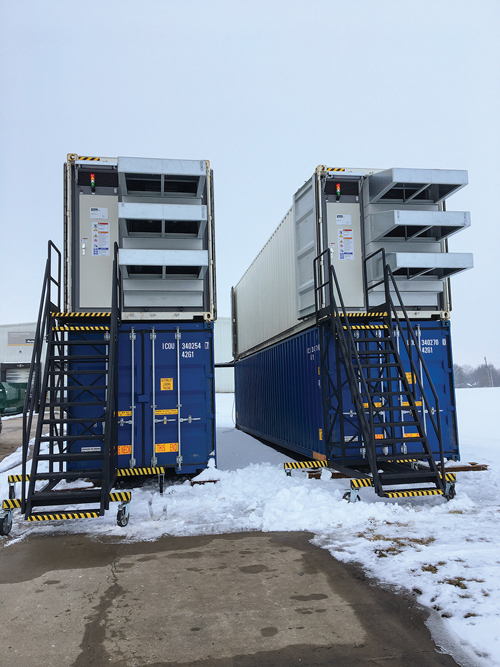
Although laboratory testing gives a guide to the performance of a filter, it should not be taken in isolation. Testing in real-world conditions is the only way to be sure that a filter will perform as expected, once installed. For this reason, testing rigs are used in remote locations throughout the world (FIG. 1). These rigs are situated to combine different environmental factors to test the real performance of filtration systems and to determine where and how improvements can be made.
 |
|
FIG. 1. Remote mobile test rig. |
Recommendations. Many considerations must be acknowledged when selecting a filtration system that can handle different components of a given installation. In a dry area with high volumes of dust, a self-cleaning pulse filter (FIG. 2) is a good option. If moisture is present, the use of coalescers will help.
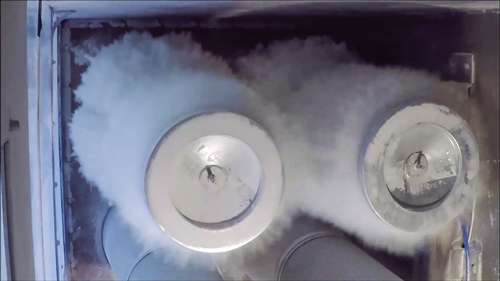 |
| FIG. 2. Cartridge filter during self-cleaning dust removal cycle. |
The selection of media also impacts how quickly a filter becomes blocked when mist or fog is present and, as general rule, glass fiber media is less prone to sudden blockages than ePTFE media in these locations. In coastal areas, salt must be considered in all its physical forms, requiring water removal stages and hydrophobic filters, as well as high-efficiency media to capture dry particles.
Ultimately, the true test of a filter’s performance is the resulting performance of the turbine. Compressor degradation, plant output, heat rate and differential pressure are all key performance indicators. Testing should be based on real-world environments and put every aspect of a filter, including media efficiency and physical aspects of its design (FIG. 3), to the test.
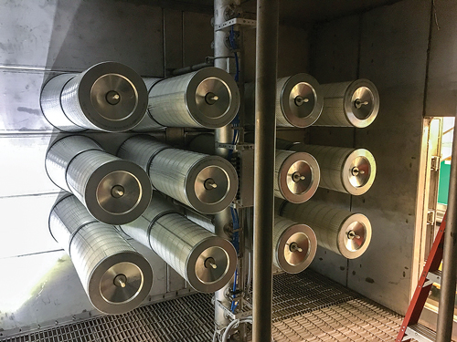 |
| FIG. 3. Self-cleaning testing equipment. |
At the end of the day, no filter is 100% efficient, and every filter will eventually become blocked. Alongside the protection of the turbine from contaminants in the air flow, the goal is to ensure long life and predictable performance, even toward end of life. This will reduce maintenance overheads, increase system availability and avoid sudden pressure spikes and unscheduled shutdowns. GP
 |
TIMOTHY AJAYI is a Specialist in developing new products and technology for commercialization, with more than 20 yr of experience in product innovation and engineering management. Mr. Ajayi is Division Engineering Manager for the Gas Turbine Filtration Group of Parker Hannifin. He has responsibility for leading, managing and providing technical direction to the product development engineering team and wider division engineering team for all new product introduction products, systems and programs.
 |
LUKE SCOTT hold a BSc (hons) degree in engineering and has more than 12 yr of experience in the gas turbine inlet filtration industry. As Lead Development Engineer at the Gas Turbine Inlet Filtration division of Parker Hannifin, Mr. Scott is responsible for the development and testing of new filtration products.


Comments