
Understanding gas sweetening processes
Natural gas produced in gas fields is a mixture of hydrocarbons, mostly C₁ through C₆+, inert gases (N₂, He, H₂, Ar, O₂), acidic gases (CO₂ and/or H₂S), organic sulfur species (RSH, RSR, RSSR) and other impurities. The H₂S content in soura natural gas spans 0.1 vol%–5 vol%, depending on the location of fields and the ages of wells, while the concentration of carbon dioxide (CO₂) ranges from 0.6 vol% to more than 15 vol%.
The acidic gases contained in natural gas must be removed in a sweetening unit to meet sales gas specifications or to match the feedstock quality requirements of LNG facilities. H₂S is toxic; it has an odor similar to that of rotten eggs when its concentration falls to 0.01 ppm–1.5 ppm. At 100 ppm–150 ppm it causes the loss of smell, and at concentrations higher than 1,000 ppm it causes nearly instantaneous death with a single breath. Sales gas specifications typically require that H₂S content be less than 4 ppm in volume.
CO₂ is non-toxic; however, if present at high concentrations it may lower the natural gas high heating value (HHV). To achieve salable gas, CO₂ content must be kept in the range of 1 vol%–4 vol%. In cryogenic units CO₂ can freeze out, causing operational problems; therefore, LNG feedstock cannot contain more than 50 ppm of CO₂.
Since the inception of the gas processing industry, dozens of sweetening technologies have been developed. This article discusses the most commonly used acid gas removal technologies, with a focus on gas absorption in alkanolamines.
Chemistry of acid gases. H₂S is a proton donator, according to the Brønsted acid definition, while CO₂ is an electron acceptor, or a Lewis acid. Both are weak acids, with CO₂ being slightly stronger than H₂S. The equilibrium solubility of CO₂ under absorber conditions is, therefore, higher than that of H₂S. However, when H₂S dissolves in water, it swiftly protonates water with one or two protons, depending on the pH of the aqueous solution, as shown in Eqs. 1–2:
H₂S + H₂O ↔ HS– + H₃O+ (1)
HS- + H₂O ↔ S2– + H₃O+ (2)
CO₂ reacts slowly with water to form carbonic acid, which successively dissociates into bicarbonate/carbonate ions, as shown in Eqs. 3–4:
CO2 + 2H2O ↔ HCO3– + H3O+ (3)
HCO3– + H2O ↔ CO3²– + H3O+ (4)
In the range of 8–10, which is the typical pH operating condition for alkanolamines, the first ionization reactions (Eqs. 1 and 3) are the predominant reactions. Therefore, the concentrations of S²– and, to a lesser extent, CO3²–, are negligible. Moreover, the absorption of H₂S is controlled by the diffusion rate through the gas film at the liquid-gas interface. Conversely, the absorption of CO₂ is controlled by mass transfer through the liquid phase, which is the controlling step of the CO₂ transport phenomenon. Overall, the absorption of H₂S is faster than that of CO₂. Under industrial absorption conditions, this results in a greater-than-expected H₂S absorption, on the sole basis of the chemical equilibrium.
The kinetics of CO₂ absorption can be improved by adding an activator to the aqueous solution. The effect is similar to that of a homogeneous catalysis. FIG. 1 shows a streamlined mechanism of an activated MDEA aqueous solution.
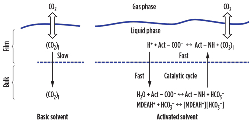 |
| FIG. 1. Mechanism of CO2 absorption with activated solvent. |
The key points of this catalysis are the high rate of reaction of the activator with CO₂, the high transfer rate of the CO₂– activator reaction product from the film to the liquid bulk, and the fast hydrolysis reaction of the formed organic acid into the activator and bicarbonate ions. In principle, the activator NH operates as a “fast shuttle,” carrying CO₂ from the film to the liquid bulk and enhancing the diffusion rate of CO₂ into the aqueous solution. The result is that, by adding a small volume of activators, a high rate of CO₂ absorption can be attained while limiting the energy required for the solvent regeneration.
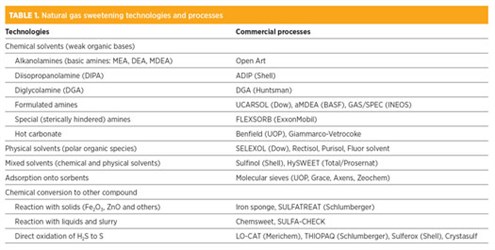
Categories of gas sweetening processes. The main categories for gas sweetening are shown in TABLE 1. Regenerative absorption into a liquid agent is the most common approach. The liquid agents can be grouped into chemical solvents, physical solvents, and mixed or hybrid solvents.
 |
The choice of solvent to be used for a specific application must consider the speciation of natural gas, along with key solvent properties: toxicity, flammability, volatility, chemical stability, reactivity, corrosivity, market availability and price.
The selection of a technology is the result of a trade-off of a number of variables, such as the gas pressure, temperature, composition, quantity of sulfur species (H₂S, COS and CS₂ and mercaptans) and CO₂ to be removed, the economic framework and the location of gas fields.
Chemical solvents. Alkanolamines are the most-used absorption media for sweetening or acid gas removal operations. These chemicals are organic bases derived from ammonia by replacing one, two or three of the hydrogen atoms with an alkyl, hydroxyalkyl or aryl group.
The alkanolamines can be classified as primary (monoethanolamine, MEA), secondary (diethanolamine, DEA and diisopropylamine, DIPA) and tertiary (methyl diethanolamine, MDEA and morpholine derivatives), depending on the number of dislodged hydrogen atoms in the amino functional group. The alkalinity of amines decreases from primary to tertiary amines. The reduction of alkalinity entails a reduction of the heat of reaction; therefore, MDEA requires less regeneration energy than MEA.
Primary and secondary amines react quickly and directly with CO₂ to form carbamate salts (R₁R₂NCOO–), which are relatively stable since their hydrolysis reaction to bicarbonate is very slow. MDEA, a tertiary amine, does not form carbamate at all, and CO₂ absorption goes through only bicarbonate ion formations. The latter mechanism is a very slow process, which explains why MDEA is more selective in the adsorption of H₂S relative to MEA and DEA.
The hydroxyl groups (–OH) of alkanolamines make the solvent soluble in water and with a high boiling point (low vapor pressure); in doing so, they help reduce solvent losses and sweetening costs.
The basic amines are often blended with various additives—activators, promoters, buffers, corrosion inhibitors and foam depressants—for specific applications, as deep CO₂ removal in the gas treatment section of an LNG plant. The additives used for the formulation can be grouped into acids (phosphoric, citric and others) and organic species carrying the –NH functional group (piperazine, MEA, DEA and others).
The composition of these formulated amines are generally considered proprietary. Process flow diagrams based on these solvents are usually provided by the solvent supplier; however, the physical/chemical properties of some formulated amines have been embedded into commercial process simulators for public use. The trademarks of some formulated amines are listed in TABLE 1.
Sterically hindered amines, a further subset of alkanolamines, are molecules specifically designed to mitigate the alkalinity of primary and secondary amines through shielding the nitrogen atom with large aliphatic groups. This supresses the fast reaction leading to the formation of carbamate. Hampering the carbamate formation slows the CO₂ absorption, thereby ensuring high CO₂ rejection at the top of the absorber column without affecting the rate of H₂S removal. High CO₂ rejection is desirable when the CO₂/H₂S ratio in the feed gas is too high for processing in a Claus unit.
These proprietary amines offer greater selectivity toward H₂S and, therefore, higher H₂S loading compared to basic amines. Their perceived high price has kept them from being generally accepted by the natural gas industry, despite the energy savings in the regeneration section; however, these amines can largely offset their initial high supply cost.
Generally, alkanolamines are subject to both thermal and chemical degradation. The former takes place in the reboiler of the regeneration tower and results in the formation of soluble and insoluble, corrosive, heat-stable salts. The chemical degradation is brought about by the contaminants contained in natural gas: O₂, SO₂, COS, CS₂, RSH and HCN. Primary and secondary amines are more vulnerable to degradation than tertiary amines.
In time, the degradation products adversely affect the performance of the process, not only because they reduce the solvent concentration and are the root cause of foaming, but also because they alter the ionic equilibrium of the aqueous chemical environment. The insoluble degradation products are typically removed from the process stream by means of mechanical and activated carbon filters installed on the cold end of the lean solvent circuit. When the concentration of soluble degradation builds up beyond a guard limit, the solvent must be reclaimed.
Physical solvents. Physical solvents are generally aqueous solutions of polar species in which acid gases preferentially dissolve. These solvents are preferred over chemical solvents when H₂S and CO₂ make up a sizeable fraction of the total sour gas; that is, when the acid gases have relatively high partial pressure. During the absorption with chemical reactions, the acid gas load (moles of acid gases/moles of solvent) is limited by the stoichiometry. In physical absorption, the acid gas load is affected only by the gas partial pressure; the higher the acid gas partial pressure, the higher the concentration of acid gas in the liquid phase.
Since gas solubility is a key driver for physical absorption, the absorption process is carried out at relatively high pressure, while the regeneration of the solvent can be achieved by stripping H₂S and CO₂ with inert gas (typically fuel gas or N₂) at a nearly atmospheric pressure, or by merely reducing the pressure in single or multistage flashing. However, when H₂S is present in the sour gas at a significant concentration, thermal regeneration (stripping) is needed to achieve the required H₂S purity.
The regeneration heat is significantly less for a physical solvent than for a chemical solvent because no chemical bond must be loosened. Moreover, as the acid gas loads are not constrained by stoichiometry, the circulation of a physical solvent is less (with other conditions remaining constant).
In addition to H₂S, physical solvents can co-absorb organic sulfur species (COS, CS₂ and RSH) and heavy hydrocarbons, notably aromatics. The latter not only may result in a possibly significant loss of production, but also in operational problems in downstream sulfur recovery units.
SELEXOL (Dow), Purisol (Lurgi/Air Liquide), Fluor solvent, Morphysorb (Uhde) and Rectisol (Lurgi/Air Liquide) are the most-used physical solvents in gas field applications. Since Rectisol operates at lower-than-ambient temperature and is a fairly complex process, its application in the natural gas industry is limited.
Hybrid solvents. These solvents are aqueous mixtures of chemical solvents (amines) and physical solvents. The hybrid solvents combine the bulk removal capability of physical solvents with the trimming capability of chemical solvents. The deeper driving force for absorption of chemical solvents due to chemical reactions allows for enhanced gas specifications.
In addition to acid gas removal, the mixed solvent can be used for the co-absorption of organic sulfur species. However, hybrid solvents, which adsorb sizable quantities of hydrocarbons, bear the same disadvantages as physical solvents.
The formulations of hybrid solvents can be tailored to the needs of specific applications—for example, to remove H₂S, CO₂, COS and CS₂, or to selectively remove H₂S in the presence of CO₂ with partial removal of COS.
Sulfinol is a well-known mixed solvent. It is a mixture of water, MDEA or DIPA, and sulfolane [(CH₂)₄SO₂]—a cyclic organic species having a higher affinity toward H₂S and CO₂ relative to water. HySWEET, a solvent suitable for H₂S/CO₂ and mercaptans (RSH) removal with low hydrocarbons co-absorption, is a hybrid solvent developed by Total.
Process flow schemes. The generalized process setup for sweetening operations combines an absorption unit and a regeneration unit operation, as shown in FIG. 2. The raw natural gas is contacted by the aqueous solvent (lean solvent) in the absorption tower, where it picks up the CO₂ and H₂S contained in the gas. The rich solvent, loaded with acid gases, is extracted from the bottom of the absorber and regenerated in the stripping tower by heating, after being flashed in the flash drum. The lean solvent withdrawn from the regeneration column, generally operated at P < 2 barg and around 125°C, is cooled and recycled in the absorber. The sweet gas extracted from the top of the absorber is routed to the dehydration unit, while the acid gas stream exiting the regenerator overhead KOD is delivered to a sulfur recovery unit.
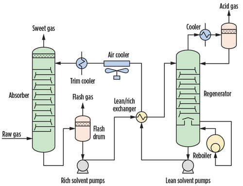 |
| FIG. 2. Regenerative acid gases removal process. |
The presence of a flash drum in the rich solvent circuit depends on the solubility of hydrocarbons in the solvent. Chemical solvents (MEA, DEA, MDEA) normally do not require a flash drum, while the physical and hybrid solvents do require it. As mentioned previously, the process schemes for physical solvents may feature multiple flash drums between the absorber and the stripper column.
The technology outlined in FIG. 2 is used in relatively large gas processing operations for removing at least 20 tpd of sulfur from natural gas. However, for smaller quantities of H₂S and when deep removal of acid gases is required, this process may prove uneconomical. In such cases, adsorption onto solid material (sorbent), chemical conversion and membrane processes may be considered.
Adsorption onto solid sorbent. In this process, the surface of a substrate attracts and captures the acid gases (adsorbates). The main mechanism though which the impurities adhere to the surface of sorbates is the van der Waals interactions.
The adsorption onto solid sorbent is a batchwise process. When the sorbent becomes exhausted, it must be regenerated through a temperature-swing process or a pressure-swing operation. The sorbents most commonly used are zeolites (molecular sieves). These adsorbent materials remove water, mercaptans and other sulfur species, in addition to H₂S and CO₂.
To achieve continuous operation, the commercial plants typically require at least two fixed-bed reactors: one in operation and the other in regeneration. Process schemes for this category will be discussed at length in the next “Back to basics” article on gas dehydration, as these schemes are similar to those used for drying natural gas in the front-end section of LNG plants.
Chemical conversion to other compound. In these processes, H₂S reacts with iron oxide (iron sponge), zinc oxide or proprietary oxides formulation (e.g., PURASPEC) to form metal sulfide species. The iron sponge, when exhausted, can be regenerated to convert Fe₂S₃ back to Fe₂O₃ and elemental sulfur, with a strictly controlled flowrate of air. The regeneration step is dangerous due the high heat of the oxidation reaction; for this reason, the oxidant injection into the system must be carefully controlled. The use of the zinc oxide process is in decline due to the difficulty of disposing of exhausted beds.
The reactants are typically loaded into fixed-bed reactors, often arranged according to a lead-lag configuration. In other technology, the metal oxide (ZnO) is kept in suspension, by a dispersant, in an aqueous solution of zinc acetate (e.g., Chemsweet).
Direct oxidation to other compound. This group includes wet oxidation processes, represented by LO-CAT and THIOPAQ. In the former, hydrogen sulfide is absorbed into an alkaline aqueous solution followed by the oxidation reaction to elemental sulfur with the redox pair Fe2+/Fe3+. The oxidizing capability of the solution is restored by blowing air through the solution.
FIG. 3 shows a typical LO-CAT process. In this scheme, the sour gas enters at the bottom of the absorber vessel, where H₂S is directly oxidized to S, and Fe3+ is converted to Fe2+. The sweet gas is extracted from the top of the vessel. The sulfur-laden solution withdrawn from the absorber bottom is routed to the oxidizer vessel, where the oxidizing property of the solution is restored, thereby converting ferrous ions back to ferric ions by bubbling air through the solution.
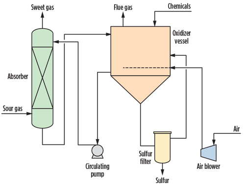 |
| FIG. 3. LO-CAT process flowsheet. |
In the oxidizer vessel, the solution is added with chelates (to keep iron in the solution), a biocide and a surfactant to ensure that the produced elemental sulfur settles to the bottom of the vessel. The elemental sulfur is withdrawn and recovered with a proprietary filter.
In the THIOPAQ process, circulating water with pH > 7 is used to absorb H₂S. The sodium sulfides that form following the absorption in water is then oxidized in the regeneration section of the unit, in part to elemental sulfur and in part to sulfate by aerobic microorganisms (Thiobacillus). Nutrients and NaOH are added to the recirculating liquid while air is blown from the bottom of the vessel. The “bio-sulfur” is recovered with a decanter centrifuge.
The sulfur recovery efficiency of these technologies can be as high as 99.9%. However, since both LO-CAT and THIOPAQ make use of an alkaline solution to absorb H₂S, they are vulnerable to the presence of CO₂ in the sour gas. Moreover, elemental sulfur produced with LO-CAT and THIOPAQ cannot meet the purity generally required for saleable elemental sulfur due to the presence of chemicals and microorganisms in the chemical environment where sulfur forms. GP
NOTES
a The origin of the term “sour gas” goes back to the earliest days of the oil and gas industry, when oil was tasted to verify whether or not it contained H₂S, which is said to taste “sour.” The removal of H₂S was designated as a “sweetening” operation, and by extension the broader removal of acid gases.
 |
LORENZO MICUCCI is a Senior Director at Siirtec Nigi SpA. He has more than 30 yr of experience in the engineering and contracting industry, most of which have been spent in the natural gas sector. In 2001, he joined Siirtec Nigi in Milan, where he directed the process design and operations department and the research and development department. During his time as R&D head, three patents have been granted to Siirtec Nigi, two of which have been implemented on an industrial scale. At present, he is the Senior Director of the technology and marketing departments. Mr. Micucci also worked for Saipem (Snamprogetti) as a Plant Designer for integrated gasification combined cycle and gas-to-liquids plants. He holds an MS degree in chemical engineering from the University of Bologna in Italy and is enrolled as a Qualified Engineer in the Register of Milan Order of Engineers.


Comments