
Calculate LNG vaporization rate during cooling of container metal
Use of the same fluid for liquefaction startup and cooling of the metal vessel and interconnected piping that contain the cold LNG may cause the fluid temperature to increase up to the boiling point and then flash into the vapor phase. During the flow of cold LNG into the system, the metal temperature gradually decreases to the fluid temperature. When the fluid and metal are in thermal equilibrium, the fluid and metal temperatures are assumed to be the same. The heat transfer rate between the metal and fluid varies over time. Initially, the heat transfer rate is at maximum, which results in the greatest vaporization rate.1
Calculating LNG vessel/piping metal temperature. The metal temperature profile over time can be obtained as per the lumped capacitance method. The lumped analysis assumes a uniform temperature distribution throughout the body, which implies that the conduction heat resistance is zero. Therefore, the lumped system results are acceptable when the Biot number ≤ 0.1, as shown in Eq. 1:
(1)
If the system containing the LNG is made of metal with high thermal conductivity and has a large heat transfer area, then the Biot number is expected to be less than 0.1. This means that the temperature of the metal is spatially uniform at any instant during the transient process—i.e., the gradient temperatures within the entire system are negligible.
In a lumped system, the fluid temperature passing through the vessel and piping assumes a constant temperature (T∞) in contact with the metal surface during the cooling process. If the cold fluid at the reference temperature flashes with no temperature change, this means that sensible heat is not considered and a higher rate of vaporization is expected; otherwise, the fluid temperature increases to the boiling point at a corresponding inlet pressure. This will be the final metal temperature at the end of the metal cooling process.
The metal temperature at any instant during the transient cooling can be estimated, using Eqs. 2 and 3:
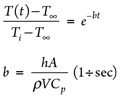 |
(2)
(3)
Here, the convection heat transfer coefficient (h) of the fluid within the vessel and interconnected piping, as per the flow regime type (laminar or turbulent) can be estimated as follows:
- For laminar flow at constant surface temperature, NuD = 3.66
- For turbulent flow at constant surface temperature while the metal is being cooled, NuD = 0.023 ReD4/5 Pr0.3
NuD and ReD can be estimated as shown in Eqs. 4 and 5:
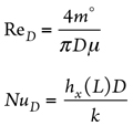 |
(4)
(5)
where:
m° = Fluid flowrate, kg/sec
D = Piping/vessel inside diameter, m
µf = Fluid dynamic viscosity, Pascal sec (Pas)
h = Fluid convection heat transfer coefficient, W/m2K
kf = Fluid thermal conductivity, W/m2K
Pr = Cp,f (J/kgK) × µ Pas ÷ kf , W/m2K
Heat transfer area (A) assumes the total geometrical inside surface area of the vessel/piping:
- Cylinder /piping inside surface area = πDiL
- Vessel head inside surface area = 0.345 πDi2 (2:1 elliptical)
= πDi2 ÷ 2 (Hemispherical)
= 0.2956 πDi2 (ASME flanged/dished)
= πDi2 ÷ 4 (Flat) - Vessel material volume (V) assumes π (Do2 – Di2) L ÷
4 + π (Do3 – Di3) ÷ 12 (2:1 elliptical)
+ π (Do3 – Di3) ÷ 6 (Hemispherical)
+ 0.0847 (Do3 – Di3) (ASME flanged/dished)
+ πDi2 × Thickness ÷ 4 (Flat) - Density (ρ) and heat capacity (Cp) are the properties of the vessel/piping material.
The total time required to cool the vessel/piping metal to the temperature of the cold liquid passing through the system (i.e., when the system reaches thermal equilibrium with the cold fluid) can be calculated, using Eq. 6:
(6)
Thermal time constant (τ) can be defined, using Eq. 7:
(7)
LNG flow temperature may increase to boiling temperature, corresponding with the inlet pressure during startup when the system is being filled with cold LNG. If LNG temperature change is not considered, then fluid flashing happens at the fluid flow temperature. However, in a rigorous design, LNG may flash at temperatures higher than the inlet fluid temperature, corresponding with the inlet pressure. This boiling temperature is the final metal temperature when the body metal and the LNG reach thermal equilibrium.
If a time range from the starting point (t0) of the cooling process to the final time (tT) (i.e., the total time obtained from Eq. 6) is divided into “n” sections, then the time stages are defined as follows: t0 = t1 – tT ÷ (n – 1); t1 = t2 – tT ÷ (n – 1); t2 = t3 – tT ÷ (n – 1) … tn – 1 = tn – tT ÷ (n – 1); tn = tT.
The metal temperatures at any given time can be obtained, using Eq. 2, at the specified corresponding time. Similarly, the heat transfer rate from warm metal and LNG flow at any given time interval can be determined, using Eq. 8:
(8)
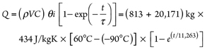
Eventually, the vaporized rates of LNG during the cooling process (as per calculated heat transfer rates) at any instance during the specified period can be determined, using Eq. 9:
m°v = Q ÷ λ (9)
Here, λ is the latent heat of LNG at inlet pressure (kJ/kg). The latent heat depends on the LNG flow pressure. The pressure change over the cooling process is assumed to be negligible; therefore, the latent heat calculation considers no change in the estimated vaporization rate.
To estimate the practical total time for the cooling process (considering estimated metal temperatures at any instant), the time intervals in which the metal temperature changes are less than 0.3°C are not considered. Since the metal temperature profile increases over time, the lowest temperature occurs at the end of the cooling process. The metal temperature approaches the fluid temperature very slowly.
The total mass of the LNG flow from the vessel into the flare system is acquired by the summation of exit flowrates for each time interval multiplied by the corresponding time intervals, as shown in Eq. 10:
(10)
where mi° = exit mass rate and Δti = time interval.
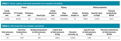
Example calculation case. For an LNG container that includes a vessel and piping, LNG enters at a temperature of –100°C and a flowrate of 20,000 kg/hr to cool the metal temperature from 60°C to the LNG flow temperature.
The vaporized rate of LNG flow into the flare header during the cooling process is determined by applying the data in TABLES 1 and 2 to Eqs. 11–17:
 |
Reynolds number within vessel = 4m° ÷ πDµ =
4 (20,000 ÷ 3,600) ÷ [π × 2.5 × (0.065 ÷ (11)
1,000)] = 43,530
Reynolds number within pipe = 4m° ÷ πDµ =
4 (20,000 ÷ 3,600) ÷ [π × (336.55 ÷ 1,000) × (12)
0.065 ÷ 1,000)] = 323,351
The Reynolds number is more than 2,300; therefore, the flow regime is turbulent.
NuD within vessel = 0.023 ReD4/5 Pr0.3 = 0.023 ×
43,5304/5 × 2.290.3 = 152; therefore, (13)
h = k × NuD = 0.11 × 152 ÷ 2.5 = 6.67 W/m2K
NuD within pipe = 0.023 ReD4/5 Pr0.3 = 0.023 ×
323,3514/5 × 2.290.3 = 755; therefore, (14)
h = k × NuD = 0.11 × 755 ÷ 0.336 = 246.7 W/m2K
Vessel surface area = πDL + 2 × Vessel head area =
π × 2.5 × 8 + 2 × π × 2.52 ÷ 2 = 82.5 m2 (15)
Pipe surface area = πDL = π × 0.336 × 10 = 10.5 m2 (16)
Thermal time constant (τ) = ρVC ÷ hA =
[(ρV ÷ hA)vessel + (ρV ÷ hA)pipe] Cp = (17)
[(20,171 ÷ 786.7) + (813 ÷ 2,609)] × 434 =
11,263 sec
The total time required for the cooling of the entire metal container to fluid temperature can be calculated, using Eq. 18:
(18)
When a time range from the initial time (t0 = 0) = to the final stage (tT = 23 hr) is divided into “n” sections, the heat transfer rates and consequent vaporized mass rates are obtained for any time interval, using Eqs. 19–20:
 |
(19)
(20)
The time intervals in which the calculated metal temperature changes are less than 0.1°C can be ignored. The required time for cooling is calculated as 16.7 hr. The total vaporized mass of LNG flow from the vessel is 1,759 kg, and the LNG vaporization peak rate of 144 kg/hr occurs at the initial time.
Takeaway. Cooling of LNG container metal by utilizing the LNG flow may lead to vaporization. The vaporized LNG rate during a transient process can be determined at any instant by using the lumped capacitance method. This method is reliable when the resistance to conduction within the metal is lower than the resistance to convection across the fluid boundary layer. This means that Biot number < 1 and, consequently, the temperature gradients within the metal are negligible.
This transient method shows that the vaporized LNG rates change dramatically over time, with most vaporization occurring at the start of LNG flow. Therefore, the total time required for cooling (FIG. 1) and the total vaporized exit mass from the LNG container into the flare system (FIG. 2) can be estimated precisely, rather than assuming a constant average rate of LNG vaporization over the cooling process.
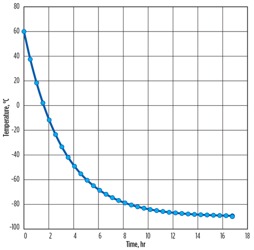 |
| FIG. 1. Total time required for LNG metal container cooling. |
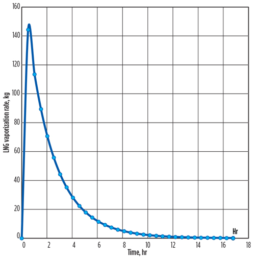 |
| FIG. 2. Total vaporized exit mass from the LNG container into the flare system over time. |
The transient process is a rigorous method to estimate lower vaporization peak rate and, consequently, lower total vaporized mass of LNG from the vessel/piping in comparison with the constant average ΔT (oC)/δt (sec) assumption.
Assuming a fixed ΔT/δt over the cooling process brings a conservative amount of vaporized peak rate into the flare header, which causes overestimation of the flare sizing. However, the transient process results in a lower total vaporized mass of LNG into the flare header system, as per a specified rate of inlet cold LNG into the container.
It should be noted that in the current transient method, no credit for convection heat transfer between the LNG container vessel/piping metal and the surrounding environment is to be taken into account. All heat (with no loss) transfers from the LNG container metal toward the cold LNG flow.
Therefore, in a conservative view, the initial metal temperature can be assumed to be the maximum design ambient temperature, which defines the maximum vaporized mass of LNG into the flare header. GP
LITERATURE CITED
- Incropera, F. P. and D. P. Dewitt, Introduction to Heat Transfer, Ch. 5 and 8, 5th Ed., April 7, 2006.
 |
HOOMAN TABARAEI is a UK-based Process Engineer working for a global engineering and construction company. He has experience in petroleum refining, petrochemicals, and offshore oil and gas platforms. He holds a BS degree in chemical engineering from the University of Tehran.


Comments