
Achieve superior LPG dispersion in LNG feed pipelines with an injection mixer
New injection mixing technology can generate superior LPG dispersion and vaporization in LNG natural gas pipelines over more traditional and conventional methods, driving evaluation of the technology in other LNG applications. A reference installation of a mixer systema has been operational since early December 2019, and the site is evaluating an increase of the injection volume by another 50%.
More traditional methods of LPG injection include atomizers, quills and static mixers, which are often fraught with plugging nozzles, uneven LPG distribution and high pressure drop. In other LNG processes, relatively large reflux columns or separator drums are utilized to separate heavy hydrocarbons.
Building on the mixer performance on feed gas conditioning, this article presents other LNG unit processes where process simulations have been performed and compared to existing process unit operations. The results presented highlight the potential for significant beneficial improvements and reduced capital expense for LNG operations.
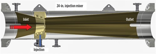
Mixer system overview. The mixer systema consists of a pipe spool with an inlet-convergent cone containing injection ports around the perimeter near the apex, and an outlet-divergent cone with a more gradual slope, shown in FIG. 1.
 |
|
FIG. 1. Mixer systema cross-section with key components. |
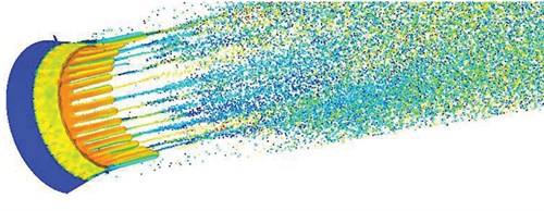
As the process flow enters the mixer, the reduction in cross-sectional area increases the velocity. The injected phase enters the process stream through channels where the feed process fluid momentum is transferred to the injected phase. This energy propels the liquid downstream to a step between the two cones, where the injected fluid is initially broken into droplets, as shown in FIG. 2.
 |
|
FIG. 2. CFD film thickness and droplet size. |
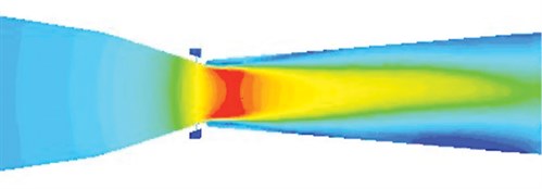
As the process continues to flow downstream, the liquid droplets intersect the “vena contracta,” and secondary breakup occurs (FIG. 3). This results in the injected liquid phase being dispersed into micron-sized droplets, maximizing the surface area for latent heat to convert the liquid droplets to vapor. By varying the injection mixer geometry to optimize the Weber number characteristics, the mixer can be designed to generate droplet dispersions best suited for the specific process requirements.
 |
|
FIG. 3. CFD velocity simulation. |
LNG natural gas feed preconditioning. Offshore production facilities often produce both a natural gas LNG feed stream and a stabilized condensate stream.
Depending on the operating temperature and pressure, the LPG components can be separated from the C5+ components, generating a stabilized liquid condensate stream and a liquid LPG stream. The LPG fraction is then injected into the natural gas pipeline for transportation to the LNG facility.
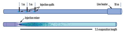
The injection mixer provides a low-pressure-drop mechanism to reinject the LPG liquid fraction into the natural gas stream to create a homogeneous, dispersed stream while avoiding the potential for liquid pooling from occurring. In one application, due to the broad turndown ratio of LPG injected and the high pressure drop, the conventional approach required three injection quills, a heat exchanger and double the flow length for complete vaporization to occur and to cover the flow range required for the system, as shown in FIG. 4.
 |
|
FIG. 4. Sketch of injection quill vs. mixer. |
Hydrocarbon dewpoint control. It is increasingly common for many LNG facilities to receive lean natural gas feed streams as sources derived from unconventional production—e.g., shale gas, coalbed methane, tight shale, etc. This often results in methane-rich feedstock that has uncharacteristically heavy hydrocarbon fractions with higher freezing temperatures than methane, which can cause operational issues with freezing and plugging process LNG liquefaction processes.
These heavy hydrocarbon components—benzene, ethylbenzene, octane and nonane—are particularly problematic and must be removed to ensure LNG liquefaction circuit reliability. NGL, including ethane (C2), propane (C3), butane (C4) and pentane (C5), are instrumental in conventional heavy hydrocarbon separator drums or scrub columns to remove the heavy hydrocarbons in a counter-current reflux stream.
As a result of the quenching performance demonstrated for conditioning LNG feed natural gas, the injection mixera was evaluated for heavy hydrocarbon stripping. Using the existing heavy hydrocarbon drum performance as a base inline, the simulation results indicate one theoretical stage for heavy hydrocarbon stripping and removal. This result equals the performance of the separator drum and suggests it can be replaced by an injection mixer and scrubber, thereby reducing the size and weight of the equipment.
In the case studied, the separator drum is 3.3 m in diameter × 6.7 m and weighs 51.6 metric t vs. the scrubber, which is less than half the size and one third of the weight. A comparison of the two solutions is shown in FIG. 5.
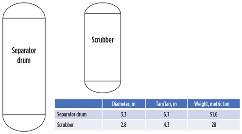 |
| FIG. 5. Sketch of separator drum and scrubber. |
Boiloff gas recovery/reliquification. All LNG facilities and terminals must deal with boil-off gas (BOG). As the name implies, BOG is LNG that has “boiled off” from its cryogenic liquid state. BOG is produced during all operational activities that require processing to avoid flaring or venting and to ensure sound environmental stewardship.
Several BOG recondenser methods and designs are available, with selection depending on the facility’s energy requirements and economic factors. The most common approach is to recondense the BOG in a BOG recondenser. In the BOG recondenser, the BOG is brought into direct contact with the cryogenic LNG liquids in a co-current downward flow for recondensation of the BOG. Recondensation efficiency is enhanced using a packed bed, where the BOG and LNG are intimately mixed and the BOG is cooled and condensed as LNG. BOG recondensers typically have a holdup section to ensure that the high-pressure LNG pumps have sufficient suction head.
Similar to the LPG quenching process, the injection mixer has the potential to replace large, bulky and costly BOG recondenser vessels by injecting compressed BOG into the cryogenic LNG flow—similar in effect to the packed-bed sections of conventional BOG recondensers. The demonstrated high turndown capability of the mixer is ideally suited for handling the fluctuating demands of BOG recondensation service.
Compressor recycle temperature control. Refrigeration systems are a key element in LNG operations. These systems have several components in common: a condenser, a compressor and evaporators. The refrigeration process is often achieved in steps to optimize the thermodynamic efficiency, with cooling of the gas at each of the compression stages.
Compressors typically recycle gas under low-flow conditions for protection. Due to the energy input of the compression, the recycle gases are hot. To prevent overheating, liquids are sprayed into the recycle stream, and the recycle stream is cooled through evaporation. The rate of cooling liquid injection is controlled by the temperature of the gas at the suction side of the compressor.
In an effort to optimize this quenching process, the injection mixer is evaluated to improve the dispersion of the injected liquid more uniformly, thereby reducing overdosing and improving the suction temperature more accurately and effectively.
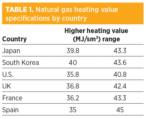
Regasification—vaporization and Btu adjustment. Natural gas comprises methane, LPG and heavier hydrocarbons, and inert components, all of which affect the heating value. As a result of the shift of LNG feedstocks to leaner gas, the heat content of vaporized LNG may need to be boosted, particularly for Asia’s markets, as shown in TABLE 1. This is often accomplished using LPG liquids (particularly propane and butane, which have higher heating value) for injection and vaporization in the LNG-sourced natural gas.
 |
A key consideration in the process of injecting LPG into natural gas to ensure uniformity of the gas composition is the mechanism of injection and dispersion. It is critical to ensure that complete vaporization of the liquid hydrocarbons occurs within a specified distance. Additionally, as with most utilities, the system must perform over a broad range of operating conditions for both natural gas and LPG flows, as industrial and consumer demand varies.
The injection mixer has demonstrated excellent performance in injecting, dispersing and vaporizing LPG in a natural gas stream with turndown ratios of 6:1 for natural gas and 80:1 for LPG. Further technology development has increased the natural gas turndown capability with equal vaporization performance.
Takeaway. The injection mixera has demonstrated excellent performance in quenching LPG in natural gas and LNG applications over a broad range of operating conditions—flow, pressure and temperature. As a result of this success, process technology companies, EPCs and LNG producers are evaluating application of the injection mixer technology across a broad range of additional natural gas and LNG processes.
Based on the initial results of these evaluation studies, it is evident that a number of process applications can benefit from significant improvements in efficiency, simplification and economic benefit. As these applications progress from evaluation to implementation, case study results will be shared with the industry. GP
NOTES
a Annular Injection Mixer (AIM)
 |
John Sabey is Chief Technical Officer of ProSep Inc. He has a strong technical background with more than 26 yr of experience in the upstream oil and gas industry. Mr. Sabey has held management and executive positions at Kvaerner Process Systems, Baker Hughes and ProSep, prior to its acquisition. He holds MS and BS degrees in mining and mineral engineering from Virginia Polytechnic Institute and State University.
 |
Yuecun (Terry) Lou is a Senior Process Engineer at ProSep Inc. He is an oil and gas processing specialist with significant experience spanning over a decade, including process design, simulation and optimization, project execution, onsite operation support and performance evaluation of commercial midstream natural gas treatment systems and inline mixing systems. Dr. Lou has a strong technical background in advanced membrane separation technologies and research and development experience for projects sponsored by the U.S. Department of Energy. He holds a PhD in chemical engineering from the University of Toledo in Ohio and a BS degree in polymer materials science and technology from Beijing University of Chemical Technology in China.


Comments