
Sectionalizing valve location on an onshore buried gas pipeline
In onshore buried natural gas pipelines, sectionalizing valves are used to divide the pipeline into smaller segments that can be isolated in an emergency case or when needed to allow for operation, inspection and maintenance activities. When appropriately located on the pipeline and properly maintained and operated, sectionalizing valves can reduce the volume of product released in the event of a buried gas pipeline failure or rupture. These valves are an important element of the reliable and safe operation of the pipeline system. When determining the placement of such valves, primary consideration must be given to the location mode (i.e., aboveground or underground) to provide continuous accessibility to the valves.1
Generally, no single option for valve location mode is correct for every application. A detailed study is needed based on project constraints (i.e., cost, schedule, etc.), pipeline terrain, risks, client preference, etc.
Valve location for onshore buried natural gas pipelines (long-distance/cross-country) has a significant impact on project cost when the number and size of the valves are increased. It also impacts the project construction timeline. This article reviews and compares American and Canadian pipeline codes for sectionalizing valve location. Also, a general comparison is made between aboveground and underground installation of sectionalizing valves on buried natural gas pipelines, based on the author’s experience in the field.
Note: It is important to remember that a detailed study must be conducted for each project. The contents of this article are based on personal lessons learned and are unrelated to any company.
Pipeline incidents and valve role. The risk of gas pipeline failure is constant and common, and many experiences and causes can lead to pipeline incidents. Prevention of pipeline failures is the primary concern of the pipeline owner, and is planned in the conceptual and feasibility phases of the project and realized during operation by considering a pipeline integrity program.
As shown in Fig. 1, pipeline valves do not prevent pipeline failures, and valves alone cannot fully mitigate the consequences of a failure. Valves only play a control role and minimize consequences in the event of a significant pipeline failure. They are part of the response, rather than prevention.2 Incorrect selection of a valve location mode in a sensitive area may incorrectly create a risk that could outweigh the benefit. Many factors must be considered in selecting the proper mode for pipeline sectionalizing valves on an onshore buried gas pipeline.
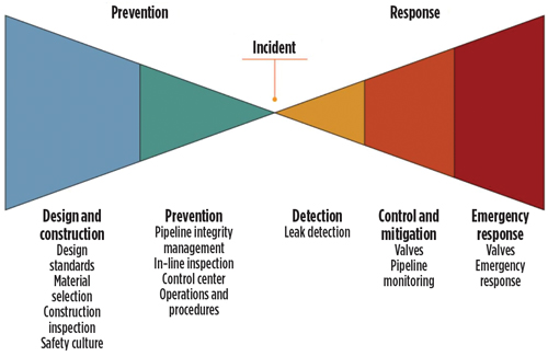 |
| Fig. 1. Pipeline incident prevention and response strategy.2 |
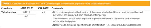
Pipeline codes in the U.S. and Canada. Natural gas pipeline regulation in the U.S. is carried out through the American Society of Mechanical Engineers’ standard ASME B31.8 “Gas transmission and distribution piping systems.”1 In Canada, pipeline codes are dictated by Canadian Standards Association standard Z662 “Oil and gas pipeline systems.”3 Both codes incorporate similar approaches regarding valve location mode for onshore buried natural gas pipelines.
Table 1 provides a tabulated version of the comparisons between U.S. and Canadian gas transmission pipeline design in terms of valve location mode.
 |
Essential factors. All codes and standards consider limited factors and minimum requirements in valve location mode. The engineering company and the owner have the responsibility of determining supplemental factors based on specific loadings, site location, known risks, level of uncertainty, geohazards, sound engineering practice, lessons learned, etc. Also, the engineer must provide the necessary protection and risk reduction mechanisms for each potential risk.
The essential factors and parameters that must be considered by the engineer for the pipeline sectionalizing valve location mode (i.e., aboveground and underground) are explained in the following subsections.
Applicable codes, standards and specifications. The first step in the selection of the valve location mode is selecting the applicable codes, standards and specifications. Many codes, standards, specifications and regulations exist for pipeline design, and each code and standard may use different criteria and limitations.
Accessibility for maintenance, operation and inspection. Proper and safe access for operation, inspection and maintenance of the valve assembly (i.e., valve body, actuator, instrumentation and stems) are important and necessary.
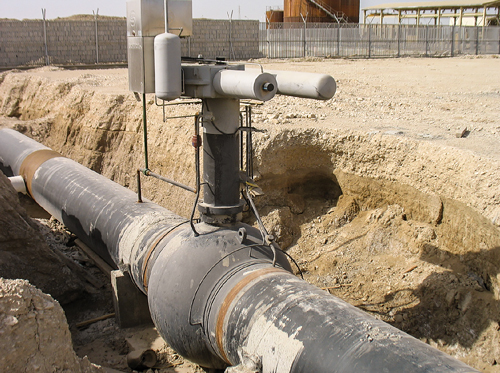
The aboveground valve installation will provide ease of access for operation, inspection and maintenance to the valve body by a proper piping design around the valve, compared to underground installation. In underground installation, the valve body is buried and is not accessible for inspection and/or maintenance. However, manufacturers normally design small-bore pipes to allow operators to lubricate, drain and vent the valve from aboveground (Fig. 2).
 |
|
Fig. 2. Small-bore pipes for lubrication, drainage and venting of the underground valve. |
Access to the valve actuator is easier with an underground valve compared to an aboveground valve, as the need for an access platform may not be necessary. If the underground valve requires major maintenance (e.g., replacing seats or repairing the ball), then the time needed for repair and/or maintenance is longer compared to an aboveground installation, due to the need to excavate, clean, remove the coating, etc.
Risk of differential settlement and movement. Buried pipelines and valves are fully restrained by the soil, and they do not typically have overbends or sag bends upstream or downstream of the valve. Consequently, they do not generally experience the axial displacements that significantly occur in aboveground valve installation. Buried pipeline valves are normally well supported by footings placed on undisturbed soil, or a precast foundation or piles, depending on the soil characteristics of the valve station. The lateral displacements to the valve are restrained by backfilled and compacted soil (Fig. 3).
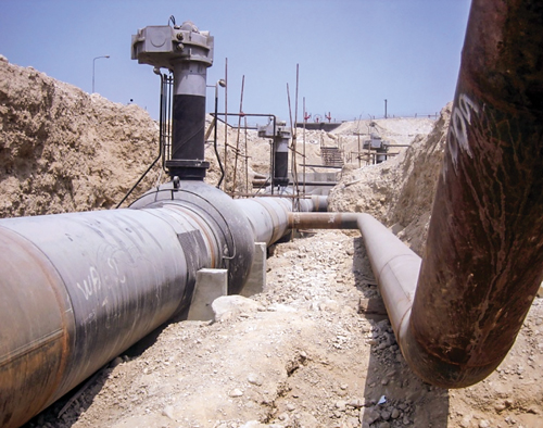 |
| Fig. 3. Installation of a 56-in. buried valve on a natural gas pipeline. |
Wind load and lightning risks. Buried valves are protected from lightning risk compared to aboveground valve installation. The effect of wind load on valve and structure around the valve must be considered during the design of the aboveground installation, especially in locations with high elevation and/or high wind velocity.
Geohazards. A geohazard is a subset of natural hazards and is an event “caused by geological contribution factors and processes that present severe threats to humans, property and natural and built environments.”4 In the context of this article, geohazards may include hydrotechnical (e.g., debris flow/flood, avulsion, scour, lateral erosion and outburst-type flood), rock slope geohazard (e.g., rockfall, rapid rockslide, rapid rock avalanche), soil slope geohazards (e.g., debris slide and avalanche, earth landslide) or seismic hazards (e.g., lateral spreading and fault rupture). These geohazards have the potential to impact the pipeline system, including the valve, and result in a pipeline failure mode (i.e., exposed or impacted pipeline, dent, buckle, leak or rupture).
Vulnerability, V(i), is an estimate of the likelihood of the pipeline failure after the geohazard has occurred, reached the right of way, and touched the pipeline or valve. The vulnerability is expressed as a conditional probability that typically ranges from 0.1 (low likelihood of failure) to 1 (high likelihood of failure).5
For a given potential of a geohazard to occur at a location, (i) along the pipeline (i.e., the occurrence factor) and the same value of annual geohazard frequency (i.e., estimated number of events of a certain size occurring each year at a specific location) and the same spatial probability of impact (i.e., the probability that a geohazard will reach the pipeline right-of-way and then touch the pipeline), the V(i) of the aboveground valve installation is much higher than the underground valve installation.
Water table. Risk of water table fluctuation and interference with the valve should be considered in underground installation. Coating for a valve body up to 300 mm–500 mm of the extension stem cover should be considered at minimum.
Coatings must have the highest possible moisture resistance to maintain their properties and be effective over a long period time. The best corrosion-resistant valve coating generally has the lowest water absorption. Also, the valve coating should have a strong resistance to the ionic passage from the exterior of a coating to the valve substrate.
The risk of coating disbanding due to cathodic protection or catching a sharp corner of the valve surface must be addressed during engineering, and proper mitigation actions should be considered. The coating must have a low moisture vapor transfer rate and very high adhesion to resist cathodic disbanding. Aboveground installation of the valves does not carry the risk of water table fluctuation or cathodic disbanding of the coating.
Overbend and sag bend. Underground installation of the valves on the buried gas pipeline do not require any overbend and sag bend combinations upstream or downstream of the valve, compared to aboveground valve installation. Those bends induce axial displacement, mainly during transient events such as operation temperature changes (e.g., weather change, startup and shutdown), which may require mitigation for displacement.
Wildfires. If the risk of wildfires exists in a specific area of the pipeline route, the aboveground installation of the valve may make the valve more vulnerable, compared to underground installation.
Environmental impact. The installation of a valve will create an impact on the environment, and the valve itself can have issues related to reliability, leakage and susceptibility to accidental damage or vandalism.4 Both underground and aboveground valve installations impact the environment, particularly sensitive areas such as national parks, protected areas, wildlife areas, archaeological and heritage sites, and other environmentally sensitive areas.
Cost and time of installation. Belowground installation of valves on a buried pipeline requires less cost and time for procurement, shop inspection, installation and construction due to the omission of unnecessary accessories, such as an access platform, S-bends, insulating joint/gasket and installation, etc., compared to aboveground valve installation. Time and cost of trenching may not be significant; however, if the size and number of the valve stations are higher, then associated costs must be considered. Both installation modes require valve stations with fences and gates, blowdowns and valves, gas detectors, remote terminal units, lighting, etc.
Corrosion protection. Aboveground installation of valves for a buried pipeline requires installation of additional insulating joints/gaskets to prevent leakage of the rectifier supply current from the underground pipeline system to the aboveground structure/piping. The underground valves will require coating and cathodic protection.
Noise. Noise will be greater in aboveground valve installation compared to underground installation. Local noise regulations must be considered during the selection of the location mode.
Risk of vandalism and external interference. Aboveground installation of a valve brings higher visibility and makes the valve more susceptible to vandalism, sabotage and external interference, compared to underground valve installation. These risks are addressed in Annex H of CSA Z662 and ASME B31.8 and must be considered during the selection of the location mode. For class locations of 2, 3 and 4, underground installation has fewer external interfaces and less risk of vandalism.
End connection. For both aboveground and underground installation of pipeline sectionalizing valves, welded end connections are recommended. It is not good engineering practice to bury the flanges, as the gasket may leak and require replacement. In addition, an aboveground valve with flange connections is not recommended for “off-plot” and unmanned installation (e.g., outside the facility fence) due to the risk of gas leakage from the flange gasket.
Valve type and dimension. The valve type and specifications are similar in both aboveground and underground installations, except for the length of the valve stem extension and the coupling between the valve and actuator, the latter of which is higher in underground installation compared to aboveground installation. No significant difference is seen in valve dimension between aboveground and underground installation of valves.
Thickness of connected pipeline. Thickness of the aboveground pipeline may be less than the thickness of the buried pipeline for the same design conditions, and may be calculated based on the same applicable codes and standards. Aboveground pipeline wall thickness is calculated based on the hoop stress. For buried pipelines with soil-pipe interaction, maximum combined stress (Hoop stress – Longitude stress) must be less than 0.9 × SMYS × Design temperature.6
Transportation and storage. The valve assembly height is greater in underground installation compared to aboveground installation; however, transportation and storage of the valves are not significantly changed nor impacted by valve location mode.
Valve spacing and class change. Valve spacing is not dependent on the mode of valve installation. Clause 4.4 of CSA Z662 states that in absence of an engineering assessment conducted in accordance with Clause 4.4.3, the spacing of valves in the pipeline shall be:
- Class 1 location: Not required
- Class 2 location: 25 km
- Class 3 location: 13 km
- Class 4 location: 8 km.
The spacing may be adjusted by up to 25% based on operational, maintenance, access and system design factors.
If there is a risk of pipeline class change in the future, additional valve(s) may be required. Underground installation is easier and less costly compared to aboveground installation. Pipeline service life is normally 50 yr or more, so the long-term development plans of cities, towns, districts, etc. should be studied with regard to the pipeline route.
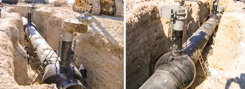
Safety and space requirements. Aboveground installation may impact public and personnel safety due to the increased noise level and the higher risk of leakage due to external interferences. In addition, aboveground valves will require more land, which can be a challenge for the owner to purchase or authorize through the municipality or landowners, the public and regulatory agencies. Installation and welding work of the buried valves has higher safety risks due to working inside the valve trench (Fig. 4).
 |
|
Fig. 4. Two views of a 56-in. buried valve welding inside the trench of a natural gas pipeline. |
Effect of weather condition. The effects of weather conditions and changes, such as direct sunshine temperature, freezing, snow load, etc., must be considered for aboveground installation. Underground valves are less impacted by weather effects and changes; however, the frost line may be a concern. The frost depth or freezing line is the maximum depth within the soil where groundwater is expected to freeze. The frost depth depends on many parameters, such as outside temperature, the amount of insulating snow cover, the heat transfer properties of the ground material, etc. Knowing the depth of the frost line in the area where the underground valve is intended to be installed is important for the design and materials selection of the small-bore pipeline.
Minimum design metal temperature (MDMT). The MDMT may change the material and impact the test requirements of the valve parts, especially the valve body. The MDMT should be decided based on the lowest operating temperature or the lowest reported ambient temperature—whichever is more severe. The engineer should use suitable MDMT considering the lowest installation temperature and the soil temperature.6
Underground installation of valves has the advantage of lower MDMT compared to aboveground installation of the valves. The valve material must meet the fracture energy and shear area requirements at the minimum design temperature. The valve body welds and the heat-affected zone (HAZ) toughness values must be validated at the MDMT. The MDMT at a specific location for aboveground valves can be assumed at –45°C; however, for underground installation, the MDMT may be decreased to –29°C, which could lead to significant cost savings for the project, especially with a high number and size of sectionalizing valves.
Takeaway. Two proven pipeline codes are generally used to design natural gas pipelines—CSA Z662 and ASME B31.8. Neither addresses detailed criteria for the installation of sectionalizing valves (i.e., aboveground or underground) on a buried gas pipeline. As such, many factors and risks must be considered for the selection of the mode of installation of the pipeline sectionalizing valves, and not just cost or ease of operation.
The author’s conclusion is that the mode of installation for the pipeline sectionalizing valves can, in some circumstances, interact to threaten the integrity of pipelines/valves and create more risk. Valve integrity, along with pipeline integrity, is of prime importance to pipeline operators, as well as to those who live and work close to the pipeline. Pipeline valves need their own inspection programs, regardless of whether they are installed aboveground or underground. Valve maintenance, inspection and integrity must be considered during installation mode selection. Incorrect valve installation mode in a sensitive area may create a risk that could outweigh the benefit. GP
Acknowledgment
The author is grateful to his daughter for assistance in editing this article.
Literature cited
1 American Society of Mechanical Engineers (ASME) B31.8, “Gas transmission and distribution piping systems,” 2018.
2 National Energy Board Website, “Fact sheet: Valves on a pipeline.”
3 Canadian Standards Association (CSA) Z662, “Oil and gas pipeline system,” 2015.
4 Nadim, F., “Introduction to the proceedings of ECI geohazards—Technical, economic and social risk evaluation,” Lillehammer, Norway, 2006.
5 Baumgard, A., “Implementing a quantitative geohazard frequency analysis framework as a component of risk assessment of new pipelines,” 2016.
6 Zardynezhad, S., “Consider key factors in pipeline wall thickness calculation and selection,” Gas Processing, February 2015.
Shahab Zardynezhad is a registered senior mechanical/pipeline engineer in Alberta and British Columbia with more than 27 yr of experience working in the world’s largest oil, gas and petrochemical projects. He has experience in many cross-country, long-distance pipeline projects including buried, aboveground, thermal, high-pressure, NGL and sour gas pipelines. He holds a BS degree in mechanical engineering from the University of Petroleum of Iran, an MS degree in industrial engineering from IUST Iran and an MS degree in mechanical engineering (pipeline specialization) from the University of Calgary in Canada.


Comments