
Manage contaminants in LNG feed gas and cryogenic processing—Part 2
The process of treating and liquefying natural gas into LNG is a complex and often delicate operation. LNG production is growing rapidly to meet demand, and processing facilities are highly profitable when designed and operated correctly. The profitability of a plant depends on throughput, which is maximized by maintaining stable operation, consistently meeting product specifications and identifying and managing contamination. These goals must be met in several systems throughout the LNG process.
Part 1 of this article reviewed requirements for contamination management, common issues in LNG processing and feed gas contamination. Part 2 presents a case study to demonstrate how proactive contamination sampling and onsite testing prevented a plant shutdown and revealed a solution to avert further problems.
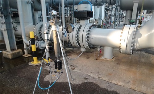 |
| Fig. 4. Sampling unit as assembled for feed gas contamination testing and sampling. |
Case study. A North American LNG plant was experiencing difficulties with fouling in the main cryogenic heat exchanger (MCHE). The heat exchanger was an aluminum, spiral-wound design that operated at low temperature as part of the liquefaction process. Small amounts of contamination were suspected to have been deposited in the gas stream in the exchanger. This contamination was thought to be acting as a seed point for further fouling and/or freezing of other contaminants. It was further suspected that contaminants could be leaching from the molecular sieve beds, where buildup and potential formation of contaminants were theorized to have been occurring.
In the spring of 2018, an analysis of liquid contamination from the mixed refrigerant system revealed C5–C14 hydrocarbons that were suspected to be coming from the feed gas. A decrease in heat transfer in the exchanger over time was determined to be taking place, and fouling was postulated as the most likely cause. The LNG facility also began having problems with amine solvent foaming, predominantly in one of its two contactor towers. The reason why only one contactor experienced more frequent and potent foaming events was unknown. The LNG facility began commercial operations in early 2018 and, after some initial challenges with amine foaming and other complications, was operating with relative stability. Foaming episodes were not a major concern until the summer of 2018, when liquids carryover from the amine contactor began to occur with increasing frequency.
It was suspected that surfactant contamination in the feed gas stream was not being removed effectively by the feed gas coalescers and, therefore, entered the amine contactor and contaminated the amine solvent. The feed gas coalescers had not been observed to collect and remove any liquids during operation, and it was unknown whether liquid contamination was present or was carrying over past the coalescer. To determine whether the feed gas coalescers were operating efficiently and identify potential options to improve their performance, the facility requested an inspection of the vessels and assistance with turnaround maintenance.
The facility processed pipeline-quality natural gas to produce LNG. The main process began with compression, then gas flowed to two amine contactors, where predominately CO2 was removed. The treated gas was then dehydrated with molecular sieve beds. Once the water was completely removed, the gas flowed to a liquefaction plant, where heavy hydrocarbons were removed. The gas was then liquefied for storage and further transport.
Onsite testing and troubleshooting. To identify contamination in the feed gas, three locations were chosen for sampling and testing—one immediately upstream of the MCHE and two farther upstream—to attempt to locate the source of the contaminants. The objectives of testing were to isolate and quantify any contaminants present throughout the process, determine their potential relation to fouling issues at the MCHE, and identify solutions to mitigate fouling. Testing was also performed at the outlet of the molsieve bed dust filter to determine if any contaminants from the molsieve bed were carrying over downstream. Testing was also performed upstream of the amine unit contactor to determine if any contaminants from the feed gas were affecting the liquefaction process.
To help determine the source of foaming, the coalescer, carbon bed and amine filters were inspected and evaluated. Antifoam usage, amine solvent quality, historical data, several operational parameters and equipment designs were also evaluated.
Gas testing. To properly assess contamination levels and contamination breakthrough or carryover in a gas stream, effective removal and quantification of all liquids in the stream are necessary. This was accomplished by using the authors’ company’s proprietary testing and sampling system.a The system uses a high-pressure housing equipped with a high-efficiency gas coalescing element designed for the capture and separation of liquid contaminants and aerosols in the gas stream. The testing and sampling system also has instrumentation to measure flow, pressure, differential pressure and liquid buildup levels. Fig. 5 shows a similar system assembled for gas testing.
The farthest upstream system, Unit 1, was devised at the inlet to the amine contactor. In addition to gas testing, Unit 1 was set up to operate a water wash injection and recirculation system to intimately contact the gas stream with water and extract any water-soluble contaminants for further analysis. The next system, Unit 2, was set up at the inlet of one of the dust filters downstream of the molecular sieve beds. The farthest downstream system, Unit 3, was set up at the inlet to the MCHE. The locations for gas testing are illustrated in Fig. 5.
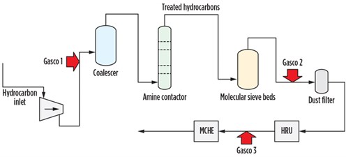 |
| Fig. 5. Gas testing connection points throughout the LNG process. |
The injection water recirculated through Unit 1 at the inlet to the amine contactors was analyzed by a number of methods to determine the presence of any gas-phase contaminants extracted. Most parameters analyzed were not of concern, but some evidence of contamination was found. Total nitrogen and carbon were quantified to determine if nitrogen-based additives, such as corrosion inhibitors and other surface-active components (surfactants), were present. The results strongly suggested that a large number of organic additives were present. The injection water sample was found to have lower surface tension compared to pure water, which further suggested that surfactants were present in the feed gas.
To characterize contaminants present in the injection water, a portion of the sample was extracted and tested using infrared (IR) analysis. The IR spectrum indicated the presence of a hydrocarbon-based component(s), similar to lubrication oil-based contaminants from a compressor. Lubrication oils and other similar oil-based additives may have been used upstream of the facility, and many of these products contain amphiphilic surfactants that can cause amine foaming and other effects.
Accumulation of liquids was observed only once, at the MCHE inlet location, upon arrival at the plant on the morning of day two. Visible accumulation of 70 ml of clear liquids with no observed haze or solids was drained from the Unit 1 sight glass into a pressurized gas sampling cylinder and sent for further analysis. It is important to note that a leak at the unit the previous night forced the plant to shut down from normal operations and recirculate gas until the plant was at steady state, and all temperatures were adjusted back to normal operations. Due to the low temperatures needed to liquefy LNG, the startup process that took place thereafter required several hours. The liquefaction process was run in a recirculation mode, until temperatures decreased enough to produce LNG.
No liquid accumulation was observed at any time other than the morning of day two at the MCHE inlet Unit 1. These results suggested that the ingression of liquid contamination with the feed gas was minimal or, at worst, rare and intermittent. The presence of liquids at the MCHE inlet only after a change in operation suggested that the ingression of liquid contamination was due to the change in operation that occurred and was present in the gas only during the recirculation mode operated the previous night.
The liquid sample from Unit 1 at the MCHE inlet was analyzed to determine its origin and characteristics. Due to the low temperatures needed to liquefy LNG, the startup process that took place thereafter required several hours. The liquefaction process was run in a recirculation mode, until temperatures decreased enough to produce LNG. The sample was found to contain a significant amount of C1–C4 mercaptans. The mercaptans contamination was suspected to have been caused by carryover from the molecular sieve bed, where cycling up of the contaminants can occur. Other components detected encompassed heavier hydrocarbons, including benzene and toluene, as well as minor amounts of dimethyl ether and acetaldehyde. The analyzed sample also included some of the feed gas components—mostly methane, ethane and propane.
At the low process temperature, heavier hydrocarbons and mercaptans may have contributed to fouling in the MCHE. The presence of heavier hydrocarbons also suggested that the upstream heavies recovery unit (HRU) was not operating effectively. In fact, this small sample of liquids was identified only once during testing, and its composition was the strongest evidence of the root cause of MCHE fouling. This cascaded a series of activities directed at verifying the HRU operation.
Foam testing. Several samples were taken from the amine system and from Unit 1 at the amine contactor inlet for foam testing to determine relative foam tendency and stability. The results, shown in Table 3, revealed the degree of amine foaming at the unit. The treatment of samples, followed by foam testing, revealed potential solutions to eliminate or reduce foaming.
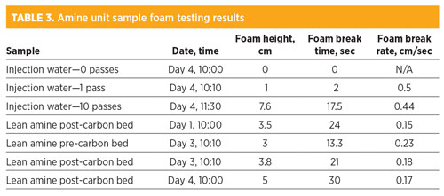 |
The results showed a number of patterns and important observations. The injection water sample cycled 10 times through Unit 1 was found to have medium foam tendency and stability relative to samples from other plants. This result showed that some surfactants were entering the amine contactor with the feed gas and likely contributed to amine foaming. Among the amine samples tested, the results were similar for all samples in terms of low-to-medium foam tendency, which showed that, while surfactant contamination was present in the amine, the degree of foaming was not very high.
It should be noted that in the spring of 2018, antifoam chemical was used continuously at the plant, or periodically on a consistent basis every day. It was unknown whether the amine contactors could run effectively without antifoam injection. It is possible that an overdose of antifoam actually made foaming increase in severity and caused other process upsets. Lower dosages of antifoam could actually improve amine foam tendency and stability. Some antifoams have a small operational window for treating, and excess product could revert it to a foaming promoter. Other antifoam products were tested with the lean amine samples to determine if a more effective product could be used at lower dosages. It was found that although the plant antifoam did reduce foam, it was much less effective than other formulations.
The authors’ company returned to the site for troubleshooting and testing when foaming issues were occurring. Samples were taken from the lean amine, reflux water and flash tank skim. The results shown in Table 4 revealed a number of patterns and important observations. The reflux water had a relatively high foam tendency for a water sample. This is unusual and indicated that surfactants had entered the amine unit and dissolved in the amine solvent, and that those surfactants were volatile or water-soluble enough that they could go overhead in the regenerator into the reflux loop. Based on the physical characteristics of the flash tank top layer and the foam tendency of the sample, it seemed likely that the sample contained injected antifoam that had accumulated in the flash tank. The lean amine sample had a foam tendency and stability that was twice as high as the samples taken in the spring of 2018. This indicated that surfactants had entered the lean amine solvent and increased the potential for foaming in the amine unit since the previous visit to the plant.
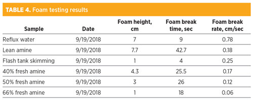 |
The other samples analyzed were makeup amine diluted to varying concentrations of water to determine the effect in terms of foaming. The results indicated that higher amine concentration reduced foam tendency. This effect has been observed at other plants and with other amine solvents. The phenomenon is not fully understood, but it is believed that the effect is caused by the reduction in surface tension inherent from the diluted amine samples.
Vessel inspections and evaluation. During the second visit to the plant, the inlet coalescer to the amine unit was inspected and evaluated to determine if the vessels showed any signs of carryover or low efficiency. Upon opening, all coalescing elements were found to be in place and installed securely inside the vessel. The elements were observed to be clean on the exterior, which suggested that solids or liquids carryover through the element media was not occurring. Additionally, the absence of staining or liquids on the element endcaps, exterior or vessel wall suggested that liquids carryover was not occurring. No evidence was found to suggest that any liquid level had been present in the upper section of the coalescer vessel. The inlet gas coalescer designs were also evaluated to determine if the vessels were adequate for the gas throughput.
The vessel sizing was first evaluated by determining critical design values for the system at the current operating conditions. Nozzle sizing and clean pressure drop was found to be within guidelines. Annular velocity—i.e., the speed of the gas flow in the void space between the elements—was just below the maximum guideline at normal operating flowrates. This is a critical parameter, since a high exit gas velocity from the coalescing elements will usually produce liquids carryover into the effluent gas stream. Carryover is common in undersized gas coalescer vessels or in vessels with deficient internal flow geometry. The effective media face velocity—i.e., the speed of gas moving through the coalescing media—was also just below the maximum guideline necessary for effective liquids interception and coalescence. Undersized vessels with an insufficient number of elements or the use of elements with low media surface area often perform poorly in terms of liquids coalescence due to high media face velocity.
The lean amine carbon bed was evaluated to determine if it was sized appropriately for the normal operating conditions for which it was in service. Key performance indicators for a carbon bed include the effective contact time and the cross-sectional velocity through the bed. Effective contact time is the amount of time that the amine stream is in contact with the activated carbon in the bed. At normal flowrates, the effective contact time in the vessel was only 13.1 min—just below the minimum recommendation of 15 min. A decrease in amine flowrate to the bed was suggested. The cross-sectional velocity through the bed is the velocity at which the fluid passes through the bed. At normal flowrates, the cross-sectional velocity in the vessel was 3.3 gal/min/ft2, below the recommended maximum of 5 gal/min/ft2.
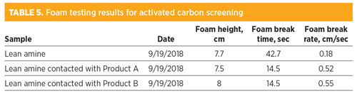
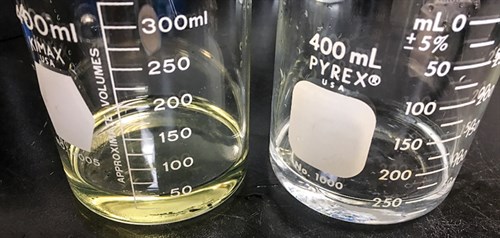
Several activated carbon products were screened for their ability to reduce foam tendency and stability in a lean amine sample taken at the plant. The amine was passed through the column at a low flowrate to achieve a contact time of 15 min. Table 5 shows the results from the activated carbon screening. The results indicated that both carbon products were effective in reducing foam stability in the amine solvent. The foam tendency, however, was not affected significantly by either carbon product. Based on the reduction in foam break time, both products were determined to be effective solutions for foam reduction, and Product A was chosen for implementation at the amine unit. Fig. 6 shows the results of the activated carbon testing.
 |
 |
|
Fig. 6. Amine solvent before (left) and after (right) activated carbon product screening. |
However, activated carbon treatment will not perform effectively if certain contaminants are allowed to enter the bed. Hydrocarbons and hydrocarbon-based additives that are insoluble in the amine solution will physically coat the carbon grains in the bed, preventing actual adsorption. It is commonly believed that a carbon bed can be used to remove hydrocarbons, but it is only actually effective at removing dissolved hydrocarbons. Free or emulsified liquids will clog the carbon grain pores and quickly deactivate the bed. Antifoam products often have the same effect, leading to a challenge where the “cure” (contaminant removal via activated carbon treatment) is prevented by the “symptom relief” (antifoam treatment to reduce foaming).
Mitigation strategies and process improvements. The central problems that triggered the onsite work and troubleshooting investigation at the LNG facility were fouling in the MCHE and foaming in the amine unit contactor. The findings relevant to each issue and the solutions developed based on those findings resolved the MCHE fouling issue and mitigated amine unit foaming to an adequate level.
MCHE fouling. Feed gas testing at each of the three locations resulted in little to no liquids accumulation except at the MCHE inlet location, where 70 ml were collected over the course of one night. This liquids accumulation may have been caused by process upset. The contaminants, identified as heavy hydrocarbons and mercaptans, likely contributed to fouling and freezing at the MCHE.
The mercaptans were determined to be coming from the molecular sieve beds. The molecular sieve beds appeared to have accumulated mercaptans that desorbed in the regeneration gas. Small concentrations of mercaptans in the feed gas to the molecular sieve beds likely built up slowly over time, until the sieves were saturated and began to release contaminants downstream. Due to the closed system design, it takes the fuel gas longer to remove the mercaptans, which can only be released in the treated gas over time.
The heavy hydrocarbons found in the liquid sample collected at the feed to the MCHE were present due to inefficiencies at the upstream HRU. This problem was identified only because of the contamination found during gas testing at the MCHE inlet. The HRU was found to be having difficulty removing heavy hydrocarbons in the past due to a leaner-than-expected feedstock. The lean feed resulted in less liquid hydrocarbon solvent available to effectively scrub the gas. This issue was remedied in the past, but it was discovered as a result of onsite testing that the issue was recurring during startup operations. Necessary changes were made to the startup procedure to prevent heavy hydrocarbon carryover. Also, operations were adjusted to prevent reduced efficiency at the HRU after an upset. This prevented further fouling of the MCHE.
Feed gas conditioning. Several observations made during the inspections suggested that liquids carryover was not occurring from the feed gas coalescers. Determination of critical design values for the feed gas coalescer revealed that the vessels were operating on the edge of guideline conditions, so any increase in flowrate could have caused liquids carryover to occur.
One option to improve critical design values for the feed gas coalescers was to operate both coalescing vessels in parallel with split flow. This would improve critical design values to within guidelines for optimal operation and would ensure that the coalescers perform as well as possible to prevent liquids carryover. This dual mode of operation was recommended to the facility.
The water injection and recirculation testing conducted at the amine contactor inlet showed that water-soluble contaminants in the feed gas were entering the amine unit and likely affecting the foaming tendency of the amine solvent. The installation of an effective water wash injection upstream of the amine unit gas coalescers to remove surfactants was demonstrated to be a potentially effective solution for reducing surfactants entering the unit in the gas phase. Water wash systems are often used as a “catch-all” tool to remove many contaminants from the feed. In addition to gas phase contaminants that are soluble, water washes help remove liquid water and hydrocarbons by improving coalescing.
Amine conditioning. The lean amine sample had a relatively high foaming tendency for an amine solvent sample, as well as a high foam stability, indicating that surfactants were present in the lean amine solvent that increased the potential for foaming in the amine unit. The foam tendency increased over time since the first visit. Surface tension and rheology results supported these findings.
Foam testing results also showed that increased amine solvent concentration reduced foaming tendency. Increasing the amine solvent concentration was not feasible at the time of onsite testing, but if foaming issues became unstable or persistent, then the option would be considered.
Antifoam testing using lean amine samples from the plant showed that the plant antifoam was moderately effective, but only at relatively high dosages. Other antifoam products were tested and observed to work more effectively at lower dosages. A specific product (AF-12) was recommended for use at the amine unit.
The reflux water at the regenerator section had a relatively high foaming tendency for a water sample, which indicated that (1) surfactants had entered the amine system and dissolved in the amine, and that (2) those surfactants were volatile or water-soluble to go overhead in the amine unit regenerator. It was recommended that the reflux water be discarded over certain periods of time to help reduce contaminants. Discarding the reflux water can be an effective mode of removing surfactants from the process, instead of returning them to the unit and potentially exacerbating foaming issues.
The lean amine activated carbon bed design and key performance indicators were evaluated. The effective contact time was determined to be below the recommended minimum of 15 min. It was recommended that the amine flowrate into the bed be reduced slightly to achieve a minimum 15-min contact time. Analysis of the spent activated carbon sample revealed that the carbon was coated with plant antifoam, amine and possibly hydrocarbon contaminants. Hydrocarbons and antifoam will reduce carbon bed capacity and lifetime. The activated carbon was also found to not be the most effective available, and another activated carbon with reduced foam stability was chosen for implementation at the facility.
Hydrocarbon ingression to the carbon bed should be kept to a minimum, primarily by preventing ingression with the feed gas to the contactor. Hydrocarbon ingression was reduced by following all of the previously indicated recommendations for the gas coalescers. Hydrocarbon ingression was also minimized by increasing the flash tank residence time and by regularly skimming the flash tank to remove hydrocarbons and antifoam buildup. Antifoam ingression into the lean amine stream will invariably deactivate the activated carbon bed and reduce its lifetime. Reducing antifoam injection by using a more efficient antifoam will also increase activated carbon bed run time.
Concluding remarks. After addressing the root causes of fouling at the MCHE and foaming in the amine unit contactor, solutions were established considering all evidence, data and careful observations. These solutions were developed based on extensive onsite testing, detailed data analysis and thorough process evaluations and simulations.
As observed in this and other LNG facilities, a multitude of factors often lead to process performance difficulties. One of the most relevant factors in foam and fouling promotion was found to be the presence of inlet contaminants. Contamination sampling, testing, and further separation and control strategies for any process unit is and will continue to be a critical step for ensuring stable and reliable plant performance. The majority of the plants that do not consider this important step are often challenged against foaming and fouling episodes in addition to high operating costs, low reliability of equipment and other adverse situations that can have direct impacts on overall plant economics. GP
NOTE
aGASCO (GAs Super COalescer) system
David Engel has more than 25 yr of industrial experience in a variety of chemical engineering and chemistry areas. He is the inventor in 22 U.S. patents and the author of a number of technical and scientific papers. Dr. Engel has developed business and technology for Eastman Kodak, Eli Lilly, Pentair, General Electric and Sulphur Experts worldwide. He has specialized in chemical engineering, process chemistry, optimization and contaminant removal technologies. Dr. Engel is the Managing Director of Nexo Solutions and the Technology Leader for Exion Systems. He holds a BS degree in industrial chemistry, an MS degree in chemistry and a PhD in organic chemistry. He is also Six Sigma and Project Management certified. Dr. Engel is President of the American Filtration Society, Southwest Region; and a member of the Gas Processors Association Technical Section M, as well as a member of the boards of directors at several companies.
Cody Ridge is a Lead Process Engineer at Amine Optimization Company and a Chemical Engineer from Texas Tech University in Lubbock, Texas. He is responsible for field engineering and technology development with Amine Optimization. Mr. Ridge has worked as an operator and process engineer in the Permian Basin.
Scott Williams is a Process Engineer at Amine Optimization. He has industry experience in a number of projects in oil and gas, petrochemical, chemical and water treatment applications. As part of the Amine Optimization engineering group, Mr. Williams is responsible for technical design and solutions development in engineering and technology applications. He also provides support for analytical and specialized service projects. His recent work has been focused on amine unit contamination control, process stability and energy reduction. Mr. Williams holds a BS degree in chemical and biological engineering from the University of Colorado at Boulder.


Comments