
Opportunities for increasing efficiency in small- to mid-scale LNG plants—Part 2
R. Galavotti, Consulting Engineer, Milan, Italy
Several factors are incentivizing lifecycle cost (LCC)-focused production capacity for mid-scale LNG. These factors include the dramatic increase in cost experienced for projects after 2008, the risks of investments related to market uncertainties, the debut of floating LNG (FLNG) and the possibility to access open-art technologies for LNG liquefaction.
Small-scale LNG plants (i.e., those with capacities of less than 1 metric MMtpy) can minimize the investment required by reducing capacity, thereby reducing risks for investors. However, efficiency is a significant driver in design when owner-operated plants are based on a tolling model. This article assesses opportunities in small- and mid-scale LNG plant design. The consistent selection of cooling medium, compressor drivers and power generation can bring value to such projects, particularly FLNG and brownfield plants. Reducing annual production, exporting thermal and electrical power, or using renewable power for operation are a few ways to achieve more efficient and sustainable designs for LNG plants.
LNG seasonal production profile. To better understand the impact of cooling medium and temperature selection for design, a qualitative cross-comparison was performed on a study8 of a simulated, air-cooled, mixed-refrigerant (MR) LNG process and a power augmentation study9 by RasGas of an installed, water-cooled MR process for three parallel trains.
The cases considered in the two studies are comparable in terms of refrigeration process (MR), climate (Middle East location) and gas turbines (heavy duty). The main differences are that the first study used a simplified simulation model for a plant designeda to deliver 4.64 MMtpy of LNG at an air temperature of 28°C and 4.49 MMtpy of LNG at an air temperature of 36°C, while the second study examines a water-cooled, 4.7-MMtpy plant already in operation.
 |
|
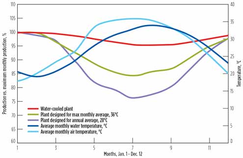
FIG. 5. Seasonal production variation for air-cooled, MR LNG process designed for different air temperatures and water-cooled, MR LNG process. Data are inferred by the author based on plotted diagrams.8 |
Note: Exchanger cooling in the second study was performed by indirect cooling. This means that the process exchangers were cooled by an inner cooling water closed loop, where the water temperature was at least 3°C–4°C higher than seawater temperature and, therefore, was comparable or slightly exceeded air temperature in the warmest month.
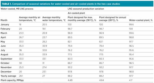 |
Table 1 and Fig. 5 show that the LNG monthly production is reported as a percentage of the maximum monthly production for the air-cooled plant designed for the highest monthly average air temperature (36°C), the air-cooled plant designed for the average annual air temperature (28°C) and the water-cooled plant. Based on the comparisons in Table 1, the associated diagram in Fig. 5 and the data from the first study, the following information can be inferred:
- Maximum production will occur in the coldest month, as long as no bottlenecking is present in the equipment design. The last statement means that even if a cooler-temperature scenario is an off-design point, overall production will increase due to the higher cooling duty available and the improved performance of the gas turbines. The increase in production can be achieved in the case of no limitations on handling a production surplus in either the equipment or process.
- The lower temperature of the cooling medium decreases the propane condensing pressure, thereby reducing the specific power demand. Gas turbine efficiency improves at lower temperature, delivering the same amount of power with lower fuel gas consumption. Both behaviors work to decrease the specific power consumption or, better, to produce more LNG than in cooler weather. However, limitations to this effect can come from:
- Stonewall margin on propane compressor can limit the circulated flow
- Gas turbines have mechanical limitations (with lower temperature, power can increase up to certain limits)
- Propane must always be kept above atmospheric pressure in a propane loop
- This physical limit set a limitation on precooling duty; in addition, a decrease in the cooling medium temperature means that the need for precooling is also reduced, causing the propane compressor to work in recycle mode and waste power.
- The water-cooled plant has a limited seasonal variation for production, with a gap of 2.3% between the average and maximum production volumes and a gap of 4.6% between the minimum and maximum production volumes, mainly due to limits on the available power from the gas turbines (limits are due to ambient air temperature, hot air recirculation and other issues). It was concluded that summer production loss could be fully recovered by the installation of gas turbine inlet air cooling.
- The air-cooled plant delivers maximum yearly production when it is designed for average annual temperature; however, the gap between the average production rate (530 tph) and the maximum production rate (602 tph) is approximately 14%. This difference can be considered as an equipment overdesign that is needed to achieve increased production during the coolest month to offset decreased production in warmer months.
- If the air-cooled plant is designed for the highest monthly average temperature, it delivers a smaller yearly production volume than in the case of average yearly temperature design; however, the gap between the average production rate (512 tph) and the maximum production rate (557 tph) is only 8%.
Based on the outlined considerations, swings in cooling medium temperature are an opportunity to consider during the design phase; however, plant CAPEX is not well allocated if the plant is designed to produce less LNG in warmer months. Flattening LNG production allows for better utilization of equipment capacity, potentially decreasing the ratio between CAPEX and LNG production.
 |
|
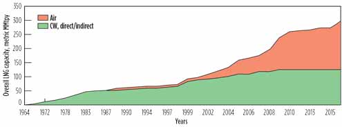
FIG. 6. Cooling medium trends in the LNG industry.10 |
Cooling medium selection. Air cooling is the preferred cooling medium in industry for onshore LNG plants, largely due to its “plug-and-play” installation concept (Fig. 6). Air cooling was first used in the North West Shelf project to accommodate environmental constraints.2
While air coolers can be installed on pipe racks, with significant advantages for modularization, the use of seawater requires extensive study (direct/indirect configuration, material selection, water intake, treatment and discharge, underground layout, piping, etc.) and construction activities (excavation and concrete bulk works).
In addition, the type of cooling medium to be used must be decided in the pre-FEED phase, when plot plan and site information can be limited; there is high potential for an increase in CAPEX related to the cooling water system during FEED execution, as well as a higher compliance risk.
The use of seawater is subject to a public authority permit. Environmental regulations are becoming stricter, with the risk of loss of containment posing a significant risk to company reputation. Water chemistry management requires skills to avoid fouling, while corrosion from seawater can be prevented using expensive materials, such as titanium, for exchangers.
The use of air has risks, too. Heat recirculation is a higher concern for an air-cooled plant than a water-cooled plant, and air temperature can drop suddenly during a storm. The resulting step change in cooling duty can lead to a pressure decrease for the compressor discharge, potentially affecting the stability of the process. Finally, yearly average air temperature is showing an increasing trend within the range of 0.5°C–1.3°C over 30 yr (the expected lifetime of an LNG plant) due to climate change.
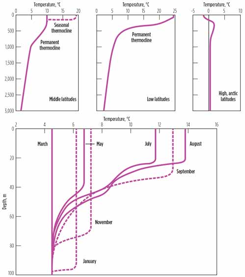
Cooling water is used on LNG floaters. Pumping the water from the border of the epipelagic zone with the thermocline allows it to remain cool and steady during the year. The upper layer—the so-called epipelagic zone or mixed layer from where cooling water is normally taken for onshore plants—is the illuminated zone at the surface of the sea, so its temperature is affected by solar radiation (Fig. 7) and is constant with the mixed layer. Below the mixed layer, at the border with the thermocline, the water temperature is cooler and steadier along the year. The border of the thermocline changes with latitude and, in mid-latitude, with the seasons; but it is not deeper than 200 m.
 |
|
FIG. 7. Typical mean temperature profiles for different latitude belts in the open oceans (A–C), with the detail of succession of temperature profiles to show the growth (solid lines) and decay (broken lines) of a seasonal thermocline in the Northern Hemisphere (D).11 |
Another significant difference is that, for floating plants, there is no risk of heat recirculation. Warm water is discharged onto the surface of the mixing level; whereas with onshore plants, there is a slight possibility for the warm water hot plume to be recirculated into the suction.
Compressor drivers selection. If water is selected as the cooling medium to flatten LNG production along the year, then the power still available for refrigerant compressors will be limited in warm periods if the plant is driven by gas turbines. This can cause fluctuations in production, albeit within a narrower range.
Steam turbines were used as refrigerant compressor drivers in the early development of the LNG industry, but they were gradually abandoned for gas turbines, which do not require boilers or water treatment. However, steam turbines were resurrected for the Tangguh LNG plant’s combined-cycle power generation and for the compressor drivers for Prelude FLNG.12,13
Steam turbine performance is not sensitive to air temperature when backpressure steam turbines or condensing steam turbines use cooling water for the condensers. Although they are less common today, steam turbines have significant advantages:
- Simpler operation and less required maintenance than gas turbines
- Steam can be produced by waste heat recovered by a steam generation unit or by boilers using low-pressure fuel gas, which reduces the energy required to compress end flash gas for fuel gas and is safer
- Boilers are less sensitive than gas turbines to fuel gas composition changes over time
- Combustion takes place far from the gas liquefaction area
- Within acceptable limitations allowed by the compressors, steam turbine speed can be adjusted.
Performance enhancementb allows gas turbines to mitigate the power losses associated with increased air temperature. This is achieved by cooling combustion air with systems typically installed downstream of the air intake filters. These coolers or chillers introduce additional equipment, utility and electrical users, as well as a reduction in intake pressure; however, they also allow for efficiency recovery and an increase in motive fluid mass flow.
Two systems are used to decrease gas turbine inlet air temperature:
- Systems based on water cooling. Air is cooled using the latent heat of water that can be sprayed or dripped into the air stream. With this system, air can be cooled to the wet bulb temperature—i.e., typically a few degrees, depending on the humidity of air upstream of the cooler. The power recovery is on the order of a few percentage points. Water must have proper composition, not only for the smooth operation of the system but also to avoid damaging the gas turbine. A drainage system (if water is sprayed) or a mist eliminator (if water is dripped) is required because drops can also damage the gas turbine. Fogging water (i.e., atomizing water in drops of less than 40 μm in diameter) does not require a liquid removal system because water will be finely dispersed; however, in this case the use of demineralized water is mandatory.
- Systems based on chilling. In this case, a fluid cooler than saturated air is circulated in a closed loop or once through. If a refrigerant is used, it will be circulated through a closed loop with a refrigeration package. This increases the cost and plot space demand. However, the use of a refrigerant allows for a decrease in air temperature below the wet bulb temperature, thereby decreasing the temperature on the order of 10°C–20°C, with an output recovery rate of approximately 10%. Water condensate will be produced, so a downstream demister is also needed in this case, and water freezing must be avoided.
On floating plants, where water is available at a much lower temperature than air, a refrigeration package is not needed. This scenario provides another opportunity. Even when equipped with air cooling/chilling, gas turbines remain vulnerable to air temperature; in the case of temperature variation due to air chill or wind shift, a sudden variation in power can occur, affecting the stability of gas turbine operation.
Electrical motors are another option for drivers that are not sensitive to air temperature, as discussed in the following section.
Improving electrical and thermal power balance. Traditionally, LNG plants have been powered by electrical generation. It is usually more convenient for operators to produce their own electricity than to buy it. Electrical power is also a key utility that some owners prefer not to externalize. Plant efficiency can be broken down into three main parts:
- Refrigeration efficiency, expressed by the specific mechanical power for LNG production
- Refrigerant compressor driver efficiency
- The balance of plant efficiency.
Typical values for different liquefaction processes and drivers are shown in Table 2.
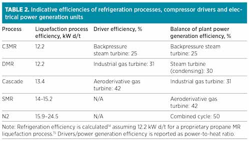 |
The balance of plant efficiency relies on electrical power and includes the heat duty recovered by gas turbine flue gases or generated by burning boiloff gas, so its efficiency relies on the efficiency of the electrical power generation system.
Major electrical power users in an LNG plant are refrigerant compressors (if motor-driven), LNG loading pumps, boiloff gas and end-flash gas compressors, amine circulation pumps, air cooler fan motors and cooling water pumps (if used).
During cooler periods, the refrigeration duty increases if the propane air coolers are kept in operation. Electrical power demand will increase due to higher air density; available power generation capacity will also increase if gas turbines are used, allowing the plant to produce more LNG.
Electrical power consumption for equipment other than refrigerant compressors is around 10 MWe–20 MWe per 1 MMtpy of LNG production. Assuming general electrical power consumption of 15 MWe/MMtpy, a 2-MMtpy plant with compressors (12.2 kW × 5,479 tpd, assuming 100% availability) and electrical generators driven by aeroderivative gas turbines (42% efficiency) will need approximately 233 MWt of fuel input. Of this amount, only 30% is used for electrical power generation, with the rest determined by refrigeration. Fuel input of 233 MWt are equivalent to a fuel gas consumption of 16.8 tph (7% of inlet gas).
However, at least half of the 30 MWe can be produced by recovering steam from the compressor gas turbine flue gases and feeding the backpressure gas turbines to produce electrical power. This combined-cycle concept integrates the process with electrical power generation, thereby reducing the plant gas autoconsumption to less than 6% (maximum). Fuel gas autoconsumption is also related to specific CO2 emissions or other combustion pollutant loads. More and more limitations are being placed on such emissions.
As an example, the Freeport LNG terminal, which is undergoing commissioning for its first train, will consist of three trains based on a proprietary propane MR liquefaction process. Each train will have a nominal capacity of 4.64 MMtpy. The plant will use electrical motors for the MR compressors (75-MWe synchronous variable-speed electric motors, the largest ever supplied for an LNG facility), and it will be the first LNG plant to rely on imported electrical power only, due to Houston, Texas-area emissions restrictions.
In fact, electric motors produce no local emissions and have energy-efficient operating characteristics over a wide range of weather and load conditions. To calculate plant consumption of external power supply, or the CO2 specific emissions rate, the CO2 emissions rate must be multiplied per kW of electric power (including the losses in electric power transmission lines). These parameters are generally not under the control of plant designers. However, designers of onshore brownfield plants may be able to select an electrical power provider with a low CO2 emissions rate per kW.
For instance, Woodfibre LNG, for which an FID is expected to be taken this year, would also source its electrical power supply externally. The power supplier, BC Hydro, produces 90% of its electricity through hydroelectric stations, which would give a significant benefit for the specific CO2 emissions rate of Woodfibre LNG.
Energy efficiency opportunities for small-scale LNG. Recent years have seen the development of several initiatives related to small-scale and mid-scale LNG export plants converted from import facilities. Small-scale LNG requires less onsite infrastructure, which partially compensates for the lower economy of scale, making the production cost attractive when coupled with the reduced investment cost.16
However, LNG plants integrated in an industrial context have significant potential to improve energy efficiency—e.g., through heat export, which has not been explored by industry. A 1-MMtpy plant will need approximately 55 MWt of cooling duty.
Water can be used to transfer heat from the plant to other possible users in the surrounding area, if the plant is located at an industrial complex or close to a community. This would allow a savings of 3.9 tph of fuel gas consumption, if used for district heating or preheating in a nearby power generation plant.
An LNG plant provided with its own power generation unit will have significant benefits if it is connected to an external grid for power export. In island mode, however, power generation must follow plant demand, meaning that the plant will not always operate at its best efficiency point.
Small-scale LNG plants have a limited need for electrical power. The possibility to access power generated by renewable sources, such as wind turbines and solar panels (now also available as floating installations), could bring advantages in terms of greenhouse gas (GHG) emissions, safety and use of plot space.
Takeaway. In the LNG market, investments are moving toward small- and mid-scale brownfield LNG plants and floating plants. Objectives are shifting from maximizing production to allocating investments in the most efficient way, not only reducing the specific CAPEX but also the entire specific LCC.
Air temperature swings, which increase with increasing site latitude, bring underutilization of plant capacity in warmer seasons; this is considered an inefficient way to allocate CAPEX. Flattening the production curve by making plant output insensitive to air temperature, as well as connecting the plant to an external power grid for export of electricity, can have significant benefits for the investment. These decisions may help stabilize the plant operation point at the maximum efficiency point, thereby limiting the offset operating scenario; however, it may also minimize the specific production of CO2.
Environmental policies will play a major role in driving sustainable designs for LNG plants. So, too, will the successful integration of competencies between the oil and gas industry and the renewable energy sector, and between process engineers and utilities and offsites designers. GP
Literature cited
8Bukowski, J. D., A. O. Weist, C. M. Ott and J. L. Trimpi, “Selecting design criteria for natural gas liquefaction facilities,” LNG 18, 2016.
9White, N. and D. Master, “Mitigation of seasonal production loss for three parallel 4.7 MTPA trains,” LNG 17, 2013.
10Source data inferred by author based on open-source articles.
11Brown, E., A. Colling, D. Park, J. Phillips, D. Rothery and J. Wright, “Seawater: Its composition, properties and behaviour,” Elsevier, The Open University, January 1, 1989.
12Prelude Floating LNG Project Draft Environmental Impact Statement, October 2009.
13Prelude Floating LNG Project EIS Supplement Response to Submissions, January 2010.
14Schmidt, W. P. and M. C. Holstine, “LNG liquefaction—’uncommon knowledge’ leads to innovation,” LNG 18, 2016.
15Vink, K. J. and R. K. Nagelvoort, “Comparison of baseload liquefaction processes,” LNG 12, 1998.
16International Gas Union, “2012–2015 triennium work report small scale LNG,” 2015.
Notes
aThe design point corresponds to maximization of LNG production at rated air temperature, achieved by the proper selection of refrigerant compressors (using polytropic efficiencies of 83%) with full utilization of the available gas turbine driver power at that temperature.
bGas turbine performance enhancement and power augmentation are often synonymous; however, some gas turbine vendors refer specifically to air cooling/chilling as power enhancement.
 |
Roberto Galavotti is a consulting engineer who helps companies develop FEED capabilities, with particular focus on LNG, energy efficiency and renewable energy. He holds a degree in civil engineering from the Polytechnic University of Milan in Italy. Mr. Galavotti has worked with engineering companies, such as Saipem, Samsung Engineering and Chiyoda, for LNG FEED acquisition, development and optimization. His main research interests include clean energy, the environment and sustainability.


Comments