
Manage contaminants in LNG feed gas and cryogenic processing—Part 1
D. Engel, C. Ridge and S. Williams, Nexo Solutions, Amine Optimization Division, The Woodlands, Texas
The process of treating and liquefying natural gas into LNG is a complex and often delicate operation. LNG facilities are highly profitable when designed and operated correctly. The profitability of a plant depends on throughput, which is maximized by maintaining stable operation, consistently meeting product specifications and identifying and managing contamination. These goals must be met in several systems throughout the LNG process.
Requirements for contamination management. Many LNG plants use a mercury removal system at the front end of the plant when any mercury is present in the feed gas. Mercury must be removed almost completely because it can cause liquid metal embrittlement with aluminum materials, namely the main cryogenic heat exchanger (MCHE) in the liquefaction process. Specialized activated carbon products, as well as transition metal oxides and sulfides, are often used as non-regenerable adsorbents for mercury removal in beds at the inlet to the plant.
Downstream of the mercury removal beds, LNG plants are fairly similar to conventional gas plants at the front end, as acid gases and water must be removed in both cases. Acid gases are almost always removed using amine units, and water is removed using either triethylene glycol (TEG) units or molecular sieve beds. The LNG feed, however, has lower specifications for acid gases and water compared to natural gas plants, so each unit must be designed for more efficient hydrogen sulfide (H2S), CO2 and water removal performance.
In some cases, a system for removing hydrocarbons heavier than methane is used to meet product specifications. Feed gas cannot be liquefied until ethane and heavier components are removed, to an extent. This is often done by contacting the feed gas with a liquid propane (or heavier hydrocarbon) stream in a column to extract any heavy hydrocarbons. Turboexpander processes are also sometimes used for this purpose, and adsorption technologies are used for lean feed gases.
The liquefaction process is the back end of the LNG plant and is directly downstream of the dehydration unit or heavy hydrocarbon removal unit. In the most common process, the gas stream is cooled by propane and then further cooled and liquefied by mixed refrigerant in the MCHE, a spiral-wound exchanger. Heavy hydrocarbon removal is sometimes implemented between the propane and mixed-refrigerant cooling stages.
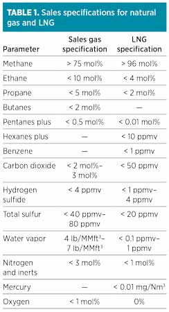
The requirements and specifications involved in LNG production are stringent and often difficult to meet and maintain. Conventional natural gas plants, by comparison, can have more lenient product specifications, as shown in Table 1. The gas purity required for liquefaction is higher than that for sales gas in several respects, such as heavy hydrocarbon content, CO2, O2 and water. Additional restrictions are present for mercury and benzene that are not of major concern in conventional gas plants.
 |
The tighter restrictions on LNG product quality result in process designs that require tighter operational ranges. Consistent operation within these ranges can be difficult at times, so significant resources must be devoted to maintaining optimal performance. Contamination control technology, testing and monitoring, and continuous operational evaluation are required to maximize and sustain long-term LNG production.
Common LNG processing issues. The rigor of LNG specifications and the large scale of production result in plant designs that can be more sensitive to process and inlet contamination with a stronger impact on unit upsets and downtime. Processing units at an LNG plant are generally operated close to their design capacities, and there is less room for excursions in process conditions at higher flowrates. The tighter specifications for LNG production stress the limits of the process’ capabilities, so additional care and attention must be taken to ensure that key operational setpoints are optimized and maintained.
Plant upsets that lead to shutdowns or reduced throughput can usually be remedied quickly in conventional natural gas plants, and the plant can be started up and returned to normal flowrates shortly thereafter. LNG facilities, however, cannot recover quickly from plant upsets. Due to the design of liquefaction units, startup can take several hours (and sometimes days) to return to the low process temperatures required to liquefy natural gas. In a conventional natural gas plant, problems such as foaming upsets in the amine unit contactor can often be resolved, and the unit can be restarted in a few hours, while a similar incident at an LNG facility can result in downtimes as long as 36 hr.
LNG facilities frequently encounter many of the same process issues observed at conventional natural gas plants, but some challenges are unique to plants with liquefaction units. Several obstacles experienced exclusively at LNG plants include:
- Variations in feed gas composition can have a significant effect on the liquefaction process. The amount of heavy hydrocarbons separated from the feed gas and used at a heavy hydrocarbons removal unit can affect the overall removal efficiency of the unit. A feed that is leaner than the anticipated design can actually result in more heavy hydrocarbons entering the liquefaction stage and causing a series of fouling problems. Ingression of mercaptans and other sulfur species can also cause fouling in the cold plant section, affecting the specification for total sulfur.
- Emissions and discharge are often limited or prohibited at LNG plants due to local laws and standards. Many plants utilize closed-loop systems for regeneration gases and effluent liquid streams that must be conditioned before reuse or disposal, and some contaminants can cycle up in these streams when reused. Makeup water streams and gas recycle lines can, therefore, direct contaminants back to the front end of the process.
- Meeting a 50-ppm CO2 specification for LNG is more difficult than the 2% specification for sales gas, and minor amounts of foaming can affect removal efficiency enough to cause missed specifications.
- Lower specifications for water content in LNG dictate that molecular sieve beds be used in most or all LNG plants. The lower water content required also dictates larger beds with tighter pores, which are more susceptible to deactivation by feed contaminants, such as amine carryover. Liquids condensation and channeling also reduce removal capacity and efficiency. Even a small upset in operational conditions can result in missed specifications for water in LNG, so proper bed operation and maintenance are imperative.
- Amine unit foaming can lead to liquids carryover and contamination of the downstream molecular sieve beds. Removing the amine solvent when present as a liquid in the molecular sieve bed can be difficult, if not virtually impossible, and can cause sieve bead mechanical fracture.
- Even minute amounts of liquids contamination or condensables in the cold plant can cause fouling or freezing in the MCHE, leading to reduced heat transfer and eventual plant shutdown. The potential for hydrocarbon condensation must be considered carefully, and removal of any free or aerosolized liquids in the gas must be carried out at very high efficiency.
Types of contaminants. A variety of contaminants with a diverse set of characteristics are encountered at every gas processing plant. LNG plants are no different in this respect, even though both the feed gas and product streams generally contain lower levels of contamination. While dealing with a cleaner feed stream is always beneficial, removing contaminants to lower levels becomes exponentially more difficult. Analysis and detection of contaminants also becomes more difficult.
Contaminants are most usefully classified according to their source, as the source is the best location to implement a solution for removal or mitigation. The knowledge and resources to identify contamination and determine its source are essential for proper process and contamination control. The most common sources of contamination in LNG facilities are the feed gases discussed in this paper. Other contaminants, such as solvents, process materials and additives, and process-generated contaminants, are important but not discussed in this article.
Feed gas contamination levels are generally lower in LNG feedstock than in conventional natural gas plant feedstock because of the pipeline-quality gas used, but this gas can still significantly affect LNG plants. In fact, feed gas to LNG plants is often the product sales gas from conventional natural gas plants. LNG feedstock has been treated in most cases, but contaminants carried over from upstream processes and transmission pipelines may still be present. Contracts for feed gas supply to LNG facilities often have stricter requirements for gas quality and composition, but not all contaminants have specifications or are even considered. In some respects, the feed gas to LNG facilities can be just as contaminated as raw natural gas. Table 2 shows some of the most commonly observed contaminants in gas feeds to LNG plants.
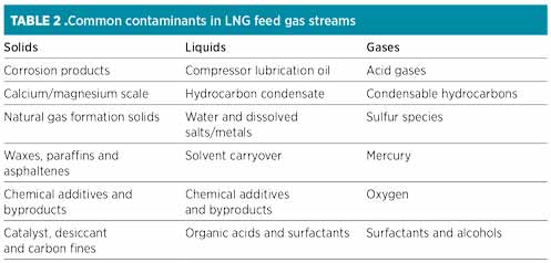 |
Some of the contaminants in Table 2, such as acid gases and mercury, are addressed with process technologies at each plant. Other contaminants, such as surfactants and chemical additives, have no dedicated solution for their removal or mitigation, so special precautions must be taken to prevent their ingression and mitigate any detrimental effects.
Feed gas contamination control. The majority of LNG process contamination originates from feed gas; therefore, proper contamination separation at the front end of the plant is one of the most important factors for the amine unit and overall plant stability. Feed gas contamination separation and control involves two main stages: (1) bulk separation and (2) polishing separation. Bulk separation involves the removal of periodic slugs and free liquids, large solid particles and large liquid droplets. Polishing separation involves the removal of low levels of contaminants, including small solid particles, liquid aerosols and extractable gas-phase contaminants. However, these low-level contaminants can affect the process significantly.
A major component of feed gas contamination separation and control is testing and monitoring. The characteristics and levels of contaminants in the feed gas must be known with some degree of accuracy to implement the correct separation solutions. The variabilities in feed gas contamination must be understood and considered in the design and operation of any contaminant removal technology. Feed gas slipstream testing is a good tool for quantifying and characterizing contaminants in both solid and liquid phases. Examples are described in the case study presented in this article.
Bulk inlet separation. In most gas plants, bulk separation is accomplished using a slug catcher and/or an inlet separator to handle large slugs and remove large solid and liquid particles. A slug catcher handles large volumes of liquids (hydrocarbon and/or water) and prevents them from overwhelming the separators downstream. An inlet separator allows the liquids to be removed from the gas by gravity settling with residence time. In some cases, oil and water are separated from each other inside the vessel. Horizontal vessels will have more liquid accommodation space and larger residence times compared to their vertical analogs.
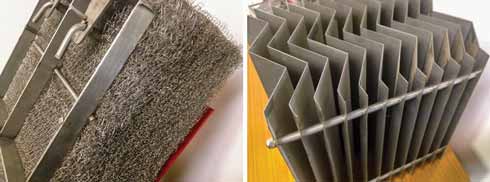
A demister pad is frequently used at the outlet of these vessels, mostly for large aerosolized liquids removal. A demister pad separates large liquid droplets (50 microns and higher, on average) from the feed gas using a tortuous wire mesh structure. If high solids are present in the gas stream, then a vane pack is used rather than a mesh pad to avoid solids plugging (Fig. 1). The vane pack has lower aerosol removal performance, but it will be less sensitive to solids and more capable of handling large liquid contents because it is less prone to flooding. Inlet devices include open pipe (sometimes with a baffle or flow distributor) and cyclonic or helical components.
 |
|
FIG. 1. Demisting devices: mesh pad (left); vane pack (right). |
Bulk separator systems are not always present at LNG plants when the expected feedstock is preprocessed gas. A small demister vessel is often the only bulk separation vessel in place. Facilities that receive sales gas directly from a conventional natural gas plant may not always require bulk separation, but feedstock sources can change or vary over time, so having proper bulk separation systems in place is always advised. A temporary or permanent change in gas supply or gradual changes in the same supply over time can result in unexpected levels of contamination that overwhelm polishing equipment and downstream systems. The decision to incorporate bulk separation for LNG feed gas should be made with consideration for any potential changes in feed gas sources, composition or transmission modes.
Fine inlet contaminant separation. Feed gas filtration should be the first contaminant removal system in place after bulk separation, as it is advantageous for several reasons—predominantly to remove solid particulates prior to polishing separation stages, such as microfiber gas coalescers for liquid removal. Filtration is critical for LNG plants because solids will foul downstream equipment, reduce the efficiency and lifetime of gas coalescers, and contaminate the amine solvent.
 |
|
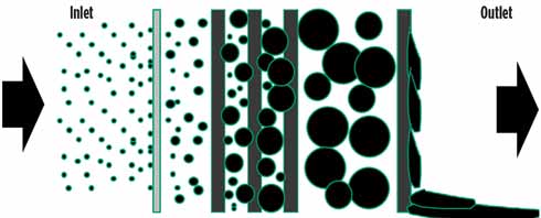
FIG. 2. Media coalescence mechanism showing interception (left), coalescence (middle) and drainage (right). |
Solid contaminants in feed gas are generally inert chemically (sand, silt, corrosion products, metal residues and solid hydrocarbons), but can vary in physical characteristics. Corrosion products are generally small, non-adhesive particles that are easy to remove economically with filtration. Waxes and paraffins, by contrast, adhere to filter media and create thin films that resist flow and require frequent filter replacement. Surface filtration elements with maximized effective surface area are ideal for feed gas filtration and more effective compared to depth filtration.
Key factors for effective gas filtration include correct materials, adequate sealing mechanisms, appropriate media pore size and rating, high effective surface area, low initial differential pressure (dP) and proper vessel design. Filtration of the feed gas to processing units is uncommon and often overlooked. Gas coalescers often act as filters when filters are not available, leading to higher operational costs and more frequent element replacements. If properly protected with a prefilter, gas coalescer elements can last 12 mos, on average.
Removal of small liquid droplets, or aerosols, as well as gas-phase contaminants that are soluble in water, is best accomplished using gas-liquid coalescing systems equipped with a water wash injection upstream. These steps can be critical for LNG plants, as aerosols and gas-phase contaminants will generally produce significant detrimental effects on amine units, molecular sieve bed operation, liquefaction plant stability and heat transfer processes.
Properly designed gas coalescing systems use a complex layering of different media materials to intercept aerosols, coalesce them into large liquid droplets, and then drain the liquids from the element’s inner structure to the bottom of the vessel. Unlike filtration media, high-efficiency gas coalescing media is an advanced technology that is difficult to manufacture correctly. The actual performances of gas coalescing elements vary considerably among different vendors and product lines. Several suppliers actually advertise high-efficiency aerosol liquid removal, only to determine after onsite testing that the performance is inconsistent with the claims. Correctly designed gas coalescer elements incorporate a suite of different materials, different layering arrangements, specific media pack densities, pleat count, pore size and flow dynamics.
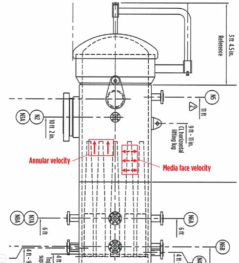
The vessel design is just as critical as the gas coalescer element design, and the coalescing process performance will suffer if both aspects are not fully addressed. Correct gas coalescer vessel designs consider a vertically designed, dual-stage system sizing for free liquids handling, proper nozzle positioning and correct instrumentation. The aerosol liquids are removed in the upper section. A number of aspects for upper-stage sizing are used and are often part of proprietary calculations. The design for the upper section of the vessel should be optimized for maximum element count and correct spacing, resulting in low annular velocities between elements, media face velocity through elements, initial dP, and flow distribution within specific design guidelines. The upper stage also has additional details, such as disengagement space, instrumentation and considerations for maintenance/ergonomic aspects. Fig. 3 shows a drawing of a gas coalescer vessel with the upper stage only and some critical parameters.
 |
|
FIG. 3. Gas coalescer design drawing depicting annular and media face velocities in vessel. |
Water wash strategies use a small water injection upstream of the gas coalescer to scrub the feed gas of water-soluble contaminants. The liquid water is then removed in the gas coalescer. Contaminants in the gas phase cannot be removed by filtration or coalescence, and water-soluble contaminants will dissolve in process solvents downstream if not removed, causing foaming, corrosion and other issues. A water wash of the feed gas is often one of the only feasible methods to remove gas-phase contaminants and can be the last line of defense against contaminants including volatile surfactants, acids and some sulfur species. Liquefaction units cannot process gas with these contaminants present. The contaminants will condense from the gas phase, causing issues in the MCHE.
Liquefaction process contamination control. The liquefaction process itself usually does not include contaminants removal, as LNG plants are designed to remove all contamination upstream. Heavy recovery units (HRUs) remove heavier hydrocarbon fractions, while molecular sieve beds and other systems remove water content from the gas. Amine units remove acid gases, and mercury beds remove mercury. Trace contaminants are removed throughout the pretreatment process via separators, filters and coalescers. Additional pretreatment systems may be in place, but are always upstream of the liquefaction process. Molecular sieve beds can also remove some mercaptans present in the feed gas. This usually poses a challenge to the facility because of the foul odor associated with mercaptans.
Several types of contaminants can impact a liquefaction process when pretreatment systems are not completely effective. Water, heavy hydrocarbons, sulfur species, solids and other contaminants have varying characteristics and effects. Due to the super-cooled temperatures, the process has virtually no tolerance for contamination. When contaminated, fouling and plugging will quickly follow, leading to decreased efficiencies and possible damage to equipment.
The only effective ways to address contamination in a liquefaction unit are to prevent it, modify operational conditions or shut down the plant to remove the contamination. Modifying operational conditions usually involves reducing throughput and results in lost revenue. Furthermore, operational conditions may need to be continually modified if the contamination issue is not resolved, which could result in a further reduction in throughput and lost revenue until a shutdown becomes necessary.
A shutdown allows the plant to remove contamination and clean process equipment, but a full investigation of the root cause of the problems is just as important. Analysis of contaminants and evaluation of the surrounding processes can reveal the source of contamination and allow for upstream solutions to prevent future upsets. Proactive contamination testing in the liquefaction unit is a valuable tool for identifying and resolving contamination ingression before reduced throughput or shutdown becomes necessary. Testing at the liquefaction unit requires a sophisticated approach and proper equipment, but it can allow contamination breakthrough to be monitored and diagnosed.
The case study presented in Part 2 will demonstrate how proactive contamination sampling and onsite testing prevented a plant shutdown and revealed a solution to avert further problems. GP
 |
David Engel has more than 25 yr of industrial experience in a variety of chemical engineering and chemistry areas. He is the inventor in 22 US patents and the author of a number of technical and scientific papers. Dr. Engel has developed business and technology for Eastman Kodak, Eli Lilly, Pentair, General Electric and Sulphur Experts worldwide. He has specialized in chemical engineering, process chemistry, optimization and contaminant removal technologies. Dr. Engel is the Managing Director of Nexo Solutions and the Technology Leader for Exion Systems. He holds a BS degree in industrial chemistry, an MS degree in chemistry and a PhD in organic chemistry. He is also Six Sigma and Project Management certified. Dr. Engel is President of the American Filtration Society, Southwest Region; and a member of the Gas Processors Association Technical Section M, as well as a member of the boards of directors at several companies.
 |
Cody Ridge is a Lead Process Engineer at Amine Optimization Company and a Chemical Engineer from Texas Tech University in Lubbock, Texas. He is responsible for field engineering and technology development with Amine Optimization. Mr. Ridge has worked as an operator and process engineer in the Permian Basin.
 |
Scott Williams is a Process Engineer at Amine Optimization. He has industry experience in a number of projects in oil and gas, petrochemical, chemical and water treatment applications. As part of the Amine Optimization engineering group, Mr. Williams is responsible for technical design and solutions development in engineering and technology applications. He also provides support for analytical and specialized service projects. His recent work has been focused on amine unit contamination control, process stability and energy reduction. Mr. Williams holds a BS degree in chemical and biological engineering from the University of Colorado at Boulder.


Comments