
Prevent premature failure of mechanical-drive gas turbines
O. Y. Zidan, S. H. Alismail, A. AL-Shiha and M. Sabban, Saudi Aramco, Dhahran, Saudi Arabia
A 24,000-hp gas turbine driving a natural gas compressor was started up for initial performance and overspeed tests, following an extended overhaul for major maintenance and upgrade to the entire train. The train was not suffering from any problematic issues, and so a normal overhaul maintenance was planned.
During the initial test runs following the overhaul, the engine tripped on over-exhaust temperature and the unit failed to restart. A detailed inspection revealed significant damage to the No. 1 bearing rotor and casings. Additional downtime was required to replace the rotor and carry out repairs.
 |
|
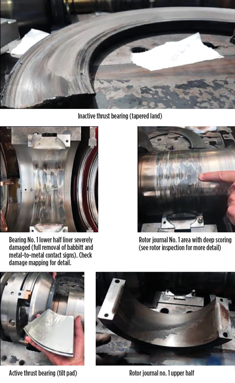
FIG. 1. Bearing No. 1 axial and radial damages. |
A root cause analysis revealed that the main causes of the bearing failure were mistakes made during the gas turbine overhaul and repair, especially related to the inspection and quality checks carried out after the major modification and alignment of the train modules.
The investigation report also highlighted several areas for improvement related to the startup checks and walkthrough, which are considered to be contributing factors to the overall failure. Causal factors, root causes and corrective actions were studied and developed to prevent the reoccurrence of such a failure.
 |
|
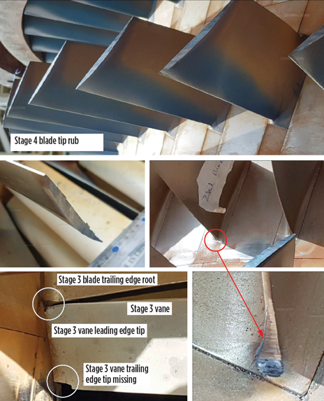
FIG. 2. Rotor and stator damages summary. |
Extent of damage. Major parts of the equipment were examined with the intent to establish damage maps and link the damages to one another. A summary of damage conditions found in the impacted areas is listed:
- The upper half of the radial bearing showed evidence of contact and a partially removed babbitt (Fig. 1).
- The lower half of the radial bearing showed evidence of heavy contact, scoring, scorching and a completely removed babbitt. In addition, axial rubbing and deformation were seen on the lower half (Fig. 1).
- The active side thrust bearing (tilt pad) was found in good condition (Fig. 1).
- The inactive side thrust bearing (tapered land) showed evidence of heavy contact and rubbing on the thrust collar (Fig. 1).
- Heavy rubbing was observed on the blade tips in stages 1–4 (Fig. 2).
- Edge damage was seen in multiple blades in stages 1–4, with the damage at the trailing edge just near the root. This indicates rotor axial movement and contact with downstream vanes’ leading tips (Fig. 2).
- Multiple chipped material and tip damage was observed on multiple vanes in stages 1–3 (Fig. 2).
- Overheat signs and discoloration were reported on the rotor aft stub shaft and on the compressor wheel in stages 9–15.
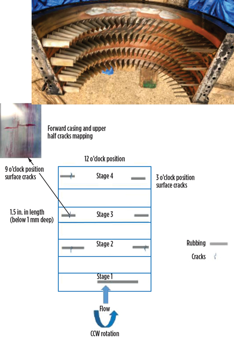
- Heavy rubbing and contact on the casing of the lower half, as well as cracks in the upper half, indicated crack mapping (Fig. 3).
- Heavy rubbing and multiple surface cracks were found in the casing of the upper half, indicating crack mapping.
 |
|
FIG. 3. Forward upper casing damage mapping. |
Cross-examination of evidence. The metallurgical analysis revealed that the bearing damages were mainly due to adhesive wear (i.e., unusual heavy contact between the shaft and the bearing babbitts). The damage to both the casing/rotor rub and bearing No. 1 support this failure scenario.
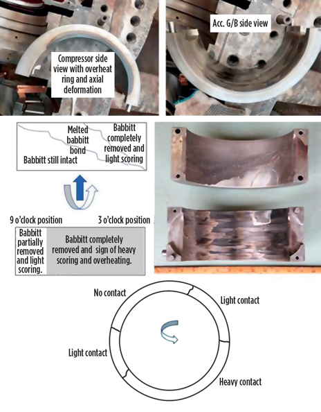
The upper half had no sign of overheat. In fact, the welded babbitts (Fig. 4) at various locations on the upper half suggested that it was running under normal temperature compared to the bottom half, which experienced unusual heavy contact.
 |
|
FIG. 4. Bearing No. 1 radial bearing damage mapping. |
With a lack of key instrumentation and information, such as XY proximity probes, bearing metal temperature and thrust axial displacement, it is difficult to positively identify the cause of unusual shaft and bearing contact—especially at turbine startup with noticeable drain temperature fluctuation.
To support such a failure scenario, the damage must be evaluated and all available evidence, especially previous healthy starts, must be cross-examined. This will allow for an accurate process of elimination. Pieces of evidence include:
- Oil pressure and temperature were stable throughout the entire period.
- Fluctuation of the bearing No. 1 drain temperature, in comparison with different previous starts, indicates trouble at bearing No. 1, either from radial or thrust bearings.
- The lab material analysis did not support the delamination of the babbitt as a possible scenario; instead, it tied the failure to adhesive wear (i.e., heavy contact between the shaft and the bearing babbitt).
- The damage mapping for both the bearing (upper and lower halves) and the rotor suggests a heavy contact pattern following the direction of rotation.
- The shaft orbit plot is not available due to a lack of XY radial bearing proximity probes.
- The possible connection between the failed lube oil pump shaft failure and the bearing No. 1 failure is misalignment, either angular or axial. This misalignment is not necessarily due to coupling alignment.
The extent of the damage suggests that the rotor side is initiating the axial force, but this cannot be confirmed without proper monitoring devices.
- No record was found of the train alignment in terms of foundation support or casing deformation, which might cause an even thermal expansion and eventually lead to heavy rubbing on the blade.
- The shaved metal initially found at the inactive thrust bearing suggests that the shaft was still heavily rubbing axially (toward the flow direction), even at low speed. This would reduce the probability of imbalance at high speed and support the failure being more related to clearance.
- Not enough acceleration was reported in one of the early startups, suggesting that more torque was required to spin the shaft at the required speed. This suggests initial malfunction or rubbing in the high-pressure compressor area.
 |
|
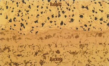
FIG. 5. Microphotograph of the babbitt and backing shows no defects. |
Root cause analysis results. Due to the lack of critical monitoring and protection instrumentation, it was difficult to indicate a single root cause for the overall failure of the turbine. The failure analysis used available evidence, including visible damage, microstructure and damage mapping. The only possible failure scenarios are listed, with the probability of combined multiple possibilities all linked to workmanship errors:
- High probability: Tight axial clearances during assembly, which were observed in all damage at the upper and lower half of the forward casing (stage 1), in the clashing of blades and vanes, in the radial bearing axial deformation, in the inactive thrust bearings, and in the axial rubbing marks in the main oil pump bearings.
- Low probability: Severe misalignment at the accessory gearbox side, leading to a bearing failure and eventual compressor blade rubbing. This would have caused the rotor to axially move toward the flow direction and overload the axial bearing.
The extent of axial damage would have required the presence of consistent and high force. The only possible scenario here is that all axial damage was subsequent to the radial bearing failure.
Prevention strategy. A summary of the prevention strategy developed in response to the findings in the root cause analysis follows:
- Develop clear policies and guidelines for the use/evaluation of non-OEM critical parts.
- Conduct a joint workshop to review gas turbine module casing alignment for the aging fleet, and develop a long-term mitigation plan.
- Review the gas turbine startup check, walkthrough and critical overspeed test procedures.
- Conduct a feasibility study to upgrade the control system logic safeguard in areas related to monitoring and protection. GP
 |
Osama Y. Zidan is a Gas Turbine Engineer at Saudi Aramco. He obtained an MSc degree in thermal power and fluid engineering from the University of Manchester in the UK. Mr. Zidan has 13 yr of work experience in rotating equipment, particularly gas turbines, including failure analysis, repair, technical consultation, standards development and project management. He is the Vice Chairman of the Saudi Aramco gas turbine standards committee and represents the company at the Saudi Standards, Metrology and Quality Organization (SASO).
 |
Sadiq H. Alismail is a Metallurgical Engineer at Saudi Aramco. He holds a BSc degree in mechanical engineering from KFUPM University in Saudi Arabia. Mr. Alismail has 17 yr of work experience, specializing in materials testing, failure analysis and materials selection. He has worked in both the downstream and upstream sectors.
 |
Abdurrahman Al-Shiha is a Gas Turbine Engineer at Saudi Aramco. He holds a BSc degree in mechanical engineering from the University of Missouri at Columbia. He has 7 yr of work experience in rotating equipment, including maintenance, failure analysis, repair and overhaul.
 |
Mahmoud Sabban has more than 20 yr of experience in oil and gas. He started his career as a plant engineer and has held various positions throughout his career in facilities planning, commissioning and startup teams, project engineering, technical support and central engineering. At present, he is a lead rotating equipment consultant and the gas turbine standards committee Chairman at Saudi Aramco. He is on the board of directors of Gas Turbine Users International and represents Saudi Aramco at the American Petroleum Institute (API) and the States of the Cooperation Council for the Arab States of the Gulf (GCC) Standardization Organization (GSO). Mr. Sabban holds an MSc degree in thermal power from Cranfield University in the UK.


Comments