
Case studies of troubleshooting amine treating foaming—Part 2
D. Engel, Nexo Solutions, The Woodlands, Texas; B. Spooner, Sulphur Experts and Amine Experts, Kemah, Texas; and M. Sheilan, Sulphur Experts and Amine Experts, Calgary, Canada
In Part 2 of this article, a second real case is presented for troubleshooting of an amine unit with foaming problems. Several foaming root causes have been determined throughout the years; however, a systematic root cause analysis is perhaps the best way to determine the origin of the foam. Whether the foam is intermittent or constant, the location of the foam (contactor or regenerators) and the position of the foam in the tower will provide valuable clues to the possible foam origin. From this information, a mitigation plan can be implemented.
Often, amine units require the use of antifoam products to control small to medium foaming events. These foaming events are normal and usually do not affect the unit and its process to a significant extent, provided that an effective antifoam is used correctly and in the right dosage.
A case with unexpected factors in an amine unit foaming event is presented in the following sections. A root cause analysis of foaming, in addition to close attention to detail, were critical for discovery and resolution of the problem.
State of the unit. A major gas facility (CO2 only, no H2S) was experiencing severe but intermittent foaming episodes in the regenerator column; in one instance, foaming was so severe that close to 20 m3 (> 5,000 gal) of amine was ejected from the unit through the acid gas vent stack. Antifoam injections failed to reduce the foaming tendency or stability quickly enough to curtail the violent entrainment of amine out of the reflux accumulator and the vent stack.
Operations personnel noted that the antifoam appeared to work well the first time it was injected, but then it seemed to be effective only every 8–10 doses, with the other doses appearing to show no change in contactor or regenerator differential pressure or having any effect on the carryover of amine. The failure of the antifoam to work properly was due to several factors, all of which are discussed in subsequent sections.
The lone antifoam injection point was focused on the hot, low-pressure, lean amine leaving the regenerator. The facility historically had only absorber foaming, so the onset of the regenerator foaming caught the plant off guard. The operators were unable to get a timely dose of antifoam into the regenerator with only a lean-side injection point.
Root causes. Troubleshooting this foaming problem required a series of checks to determine the cause of the failure of the antifoam to work properly or consistently, and the development of a strategy to reduce or eliminate subsequent foaming episodes.
Plant management was concerned not only for the cost of the lost amine, but especially for the impact of spraying amine into an environmentally sensitive area. Several questions needed to be answered to complete a comprehensive investigation of the problem:
- Is the antifoam capable of breaking down and killing a foam at the recommended dosage rate of the product?
- Does the foaming tendency remain low for a reasonable period after injection?
- Has the antifoam exceeded its recommended shelf life?
- Is the antifoam being discharged into the system at a correct dilution?
- Is the antifoam being injected at a correct rate for the system volume?
- Is the injection location optimal for the location of the foaming condition?
- What injection strategy best suits the long-term control or short-term reduction of the foaming tendency of the solution?
In this case, foam tests performed on the amine showed that during periods of upset, the amine did indeed have a recordable foam height and stability, as per foam testing protocols. The source of the foaming was not determined, as nothing obvious in the amine analysis or appearance indicated a contaminant that should increase the foaming of the amine. However, a combination of hydrocarbons (aromatics and heavy ends), along with a residual pipeline corrosion inhibitor, were suspected. The stability of the foam was completely corrected by the addition of a single drop of the onsite, silicone-based antifoam, and the foam did not return even after 3 min of continuous bubbling. The incumbent antifoam was an acceptable product for this system. All subsequent evaluations of the problem were predicated on the assumption that the antifoam in use was the correct product, and that determining why it did not work and how to make it work in the long term would be the goals of the study.
The generally acceptable statement on antifoam addition is to add the product as closely to the foaming problem as possible. Lean-side antifoam addition can be effective for absorber foaming; however, given the usual inventory cycle of 45 min to 1 hr, the addition of antifoam into the hot lean amine could take up to 30 min to reach the regenerator (if at all), given the antifoam’s propensity to float in all retention sections of the plant—especially the absorber sump and flash drum.
For regenerator foaming, antifoam addition into the rich amine or the reflux stream is recommended; however, it would be a few months before injection into this location could be undertaken. The problem needed to be solved with the only available injection point—the hot, lean amine exiting the regenerator.
The first question that needed to be answered was: Why is the antifoam being injected upstream of the lean amine filters, in such a hot location? The simple answer was that the only motive force to inject the antifoam into the system was a tank with a low-pressure nitrogen gas source. The antifoam could be injected only into the lowest pressure point in the lean loop, which was located before the booster pumps and filters. The decision was made to stick with the hot lean amine.
The second question the operators had to answer was: How best should the antifoam be prepared? It could be injected neat or diluted using water. The answer to this question was the beginning of solving the problem. To dilute the antifoam and prevent overdosing, the plant would add 500 ml of antifoam to the tank and then blend with 5 l of steam condensate. A 1:10 dilution ratio seemed to be too great a dilution factor.
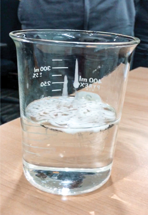
A review of the silicone vendor’s technical bulletin stated the recommended maximum dilution as three parts antifoam and one part water, so the antifoam had been diluted 30 times the recommended rate. This is not good practice with silicone emulsions because the emulsified oil used to hold the silicone solids in suspension cannot maintain its properties with an excess of water in the blend. More problematic, the antifoam will not “blend” with the water but will rather float to the top of the shot pot tank (Fig. 1). Operations staff were completely unaware that the antifoam would not blend with the amine in the shot pot tank. They assumed that they were adding a homogeneous solution of water and antifoam.
 |
|
FIG. 1. Amine solution and the separate antifoam phase. |
The plant operators indicated that the antifoam worked very well the first time it was added, but then only seemed to work sparsely (perhaps every 8–10 doses). Even after establishing that the dilution practices were incorrect, this did not explain why the first addition worked, and what happened between the first successful addition and the later unsuccessful ones.
Solutions and mitigations. To combat the initial foaming event, the antifoam tank with the now-diluted antifoam was pressurized with a small nitrogen cylinder. The valve to the hot lean amine line was then opened, allowing the product in the tank to enter the amine loop.
Unfortunately, residual nitrogen from the antifoam pulse entered the booster pumps and caused cavitation issues that were unsettling to the operators. It was decided that in the future, all subsequent antifoam shots would be cut off with a 25% residual level in the tank to avoid nitrogen bypass into the system. Even though the silicone was poorly blended (it was simply floating on the top layer of the tank fluids), the fact that the entire tank was emptied during that initial addition meant that antifoam had entered the system. Considering its foam test success, it did exactly as advertised, killing the foaming in the amine.
However, during the next five or six successive antifoam additions, in which a residual level remained in the tank, the only fluid being pumped into the process was water, as the antifoam was left floating on the top surface. This resulted in zero foam elimination after the initial successful dose. Eventually, the amount of antifoam sitting on top of the tank reached a level where some product entered the system, and the foaming problem was again suppressed. The fix was simple. Three parts antifoam to one part water was diluted and injected, as a more concentrated product, into the amine system. This new strategy made every dose an effective dose.
Eventually, through a management-of-change process, a new antifoam injection point was established into the reflux pump discharge line, which would introduce the antifoam more quickly into the regenerator and reduce the chances of carryover.
Silicone-type antifoams are not normally regarded as either continuous-addition products or even foam-preventing products, as they are normally used only to correct an established foaming condition. Nonetheless, the decision was made to add the antifoam on a “continuous-batch” preventive-maintenance dosing regime with a short pump addition at the start and the midpoint of every shift (i.e., four doses per day). The “before and after” graphs of regenerator pressure differential, regenerator tower level and reflux accumulator levels were clear. Constant cycling to absolute flatline and instances of amine carryover to the vent stack were eliminated. The flatlines allowed for the adjustment of steam ratio control, because the regenerator overhead temperature was stable for the first time in months. More consistent lean loadings, as a result of the more stable regenerator performance, meant no treated gas overages on specification.
Since the antifoam floats so quickly to the amine surface, many concerns about continuous injection of antifoam (e.g., foaming, fouling) were not realized. Any antifoam added to the regenerator simply flowed down the trays and floated at the bottom. Eventually, the antifoam reached the filtration section, where it was removed. Antifoam added to the absorber would mostly separate in the flash tank and be removed whenever the operators skimmed the vessel. Therefore, there was no risk of overdosing the system with antifoam.
Also, because this was a CO2-only facility, no iron sulfides were present. Iron sulfides can mix with antifoam to form black “shoe polish” sludge. Continuous injection of antifoam is generally not recommended; however, in some cases, it can be tolerated without negative side effects, other than the cost of the antifoam.
Takeaway. An insightful, measured approach to determining the fault in the antifoam program, followed by firm recommendations on dilution and injection policy, proved a successful solution to a problem that had plagued the client and chemical vendor for almost 6 mos. The company was satisfied that the biologically sensitive ecosystem around the plant would not be in further danger.
A multitude of factors can cause an amine unit to experience foam. In rare cases, a single factor is the main cause of foaming; more often, several factors contribute to foaming. One of the most important factors in foam promotion is inlet contaminants, so contamination control at the unit entry is a critical step for ensuring minimal foaming episodes.
Most plants that do not consider this step fight against foaming in addition to high operating costs, low reliability of equipment, and other incidents with adverse economic and environmental impacts. Other sources of foaming should also be considered, such as operational practices and the materials being used in amine plant equipment. Sometimes the culprits are found where least expected; therefore, a comprehensive testing plan with systematic analysis protocol should always be performed, not only to determine the cause(s) of foaming but also to form a plan for effective, long-term foaming mitigation.
End of series. Part 1 of this article appeared in May/June. GP
 |
David Engel is the Managing Director of Nexo Solutions and Technology Leader for Exion Systems. He has more than 25 yr of industrial experience in a variety of areas of chemical engineering and chemistry, and he specializes in chemical engineering, process optimization and contaminant separation technologies. Dr. Engel holds a BS degree in industrial chemistry, an MS degree in chemistry and a PhD in organic chemistry. He is also 6-Sigma and Project Management certified. He is President of the American Filtration Society, Southwest Region and a member of GPA Technical Section M. Dr. Engel is also the named inventor in 22 US patents and the author of many technical and scientific papers. He has developed business and technology for Eastman Kodak, Eli Lilly, Pentair, General Electric
and Sulphur Experts.
 |
Ben Spooner has been working in the amine industry since 1998 as an operator and engineer. He joined Amine Experts in 2003 and has worked in more than 25 countries and on hundreds of amine systems, providing expert assistance and advice regarding plant operations, troubleshooting, optimization and operator training. Mr. Spooner is one of the primary speakers at Amine Experts’ amine treating seminar, which has been presented in dozens of locations around the globe. Prior to joining Amine Experts, he worked as an operator at a gas processing plant in northern Alberta, and as an engineer in the technical service department of a large amine vendor based in Edmonton, Alberta.
 |
Michael Sheilan has been involved in the gas processing industry for 39 yr. He has a long history of expertise in training operators and engineers in gas processing, as well as troubleshooting all aspects of upstream gas treating processes. More recently, Mr. Sheilan has focused on dehydration and amine sweetening as a senior staff engineer for both Amine Experts and Dehydration Experts. He is one of the Principal Speakers of Amine Experts’ five-day amine treating and sour water stripping courses, as well as the four-day dehydration course. He has provided technical support to more than 500 facilities on every continent (except Antarctica). Mr. Sheilan is a registered Professional Engineer in Alberta (APEGA) and is a member of the Gas Processors Association of Canada (GPAC) and the National Association of Corrosion Engineers (NACE). He has multiple publications on topics as far-reaching as inlet separation and filtration, amine sweetening, glycol dehydration and sour water stripping.


Comments