
Optimal gas pretreatment technologies for developing FLNG projects
Floating liquefied natural gas (FLNG) technology is expected to be the next technological breakthrough for monetizing offshore stranded gas fields and transporting gas to areas of consumption. As such, there is great interest in developing robust, reliable and innovative natural gas pretreatment and liquefaction solutions for FLNG projects.
Pretreatment is a critical risk management function that can represent a meaningful portion of the costs of an FLNG facility. This article describes the optimal treatment technologies for designing a simple, compact, energy-efficient, flexible and robust pretreatment section in a floating environment subject to rocking motion. It also shows how the integration of treatment technologies and expert know-how make a difference during technology selection and design.
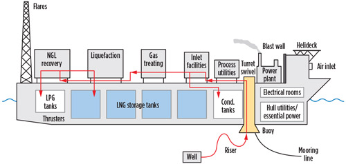
Basic design considerations. Floating above an offshore natural gas field, an FLNG facility will produce LNG at sea (Fig. 1). Offshore gas is transported via dual-insulated production flowlines and flexible risers to the FLNG facility, where impurities are removed (in the gas pretreatment section) and the gas is then liquefied before being stored onboard the facility. Pursuant to LNG, other liquid products (such as LPG and condensate) will be stored and subsequently offloaded to marine carriers for delivery to market.
 |
|
Fig. 1. Typical layout of an offshore FLNG facility.1 |
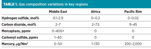
FLNG production facilities can use conventional technologies and equipment similar to onshore LNG production plants. However, there is a greater incentive to minimize topside processing due to the limited footprint and weight constraints, as well as the need for personnel refuge and escape routes in FLNG production vessels. Designing FLNG facilities intended to receive feed gas from multiple fields introduces the need for additional gas conditioning facilities when the field gas quality varies (Table 1). Gas processing equipment capable of handling well fluids with varying conditions adds to facility cost, equipment count and operational complexity.
 |
Once an FLNG facility is in operation, moving decks may present major challenges to the operability and efficiency of process equipment with two-phase flow. As such, the process technology options chosen for the FLNG facility should encourage maintaining the highest availability possible. Sometimes this may result in a less efficient design, but it will enable robust operations during changing sea states.
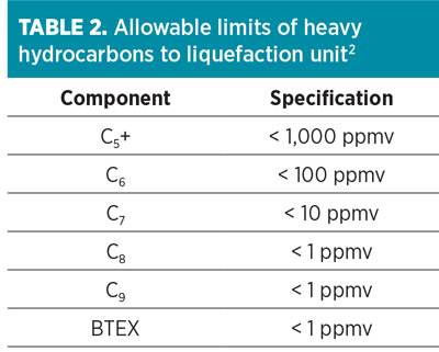
Gas pretreatment strategies. Feed gas pretreatment, which ensures conditioning of the feed gas to meet LNG sales specifications, is a vital part of any LNG process. The specifications to be met are hydrogen sulfide (H2S) removal to under 4 ppmv, carbon dioxide (CO2) to below 50 ppmv, total sulfur to less than 10 ppmv, water (H2O) to less than 1 ppmv, and mercury (Hg) to levels of 0.01 µg/Nm3. Also, heavy hydrocarbons (HHCs) must be removed to below freezing limits in cryogenic heat exchangers. The allowable limits of heavy hydrocarbons to the LNG plant (Table 2) vary depending on the liquefaction technology and process conditions.2 The basic functional requirements for designing gas pretreatment systems for FLNG facilities are more or less the same as an onshore LNG facility. On the FLNG facility, however, there is a need for a simple, compact, flexible, proven and energy-efficient pretreatment package to allow optimal uptime and avoid unwanted upsets to LNG production and project revenue.
 |
Acid gas removal. An acid gas removal unit (AGRU) removes acidic components, such as H2S and CO2, from the feed gas stream. The removal of these components helps meet the LNG product total sulfur specification and avoid CO2 freezing and subsequent blockages in the cryogenic section of the FLNG facility. The AGRU also removes some amount of carbonyl sulfide (COS), mercaptans (RSH) and other organic sulfur species that contribute to sulfur emissions.
Three commonly used solvent absorption processes for acid gas removal that also can be used in LNG plants include chemical absorption, physical absorption and mixed solvents. Commonly, H2S and CO2 are removed from the natural gas feed stream in a chemical solvent unit, utilizing an aqueous amine solvent.
With the exception of methyl diethanolamine (MDEA), amines are generally not selective and will remove both CO2 and H2S from the gas. When used in treating sour gases to meet the tight CO2 specification for LNG production, the activity of CO2 absorption is too slow with pure MDEA, which must be enhanced with a promoter; whereas a feed gas with 10 mol%–12 mol% CO2 can be handled by a promoted MDEA process.
The advantage of the amine technology is that the solubility of aromatics and heavy hydrocarbons in the aqueous solvent is low, which translates into lower hydrocarbon losses. However, the disadvantage is the high energy consumption for the regeneration of aqueous amine. Physical solvents, which can be applied advantageously when the partial pressure of the acid gas components in the feed gas is high (typically greater than 60 psi), will reduce the energy consumption but will also co-absorb more hydrocarbons. For this reason, physical solvents are generally suitable to treat lean gases.
If there is a need to treat rich gases, then the NGL must be first removed by chilling. As an alternative, the use of hybrid (mixed chemical and physical) solvents is beneficial when they can be formulated to allow for complete CO2 removal while achieving H2S removal comparable to alkanolamines.
In hybrid systems, RSH and other organic sulfur components, if present in the feed gas, can also be removed by the physical solvent portion. Generally, this option will result in an expensive design with a hydrocarbon co-absorption that is too large to be acceptable. The optimum solution in many cases is the distribution of RSH removal capabilities over the optimized mixed chemical-physical solvent, or the chemical solvent alone, in the AGRU and the molecular sieve unit (MSU).
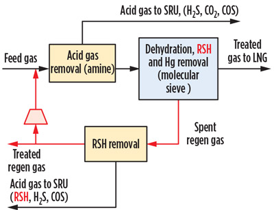
In this option, the MSU spent regeneration gas can be regenerated using an AGRU shared regeneration system, or treated in standalone physical solvent for RSH removal. Mercury can be simultaneously removed in the MSU. The treated regeneration gas can then be recycled, either to the inlet of the MSU or the inlet of the AGRU absorber (Fig. 2).
 |
|
Fig. 2. LNG pretreatment scheme with gas phase mercaptans removal. |
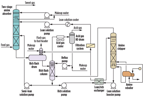
If the FLNG facility is expected to be relocated to a gas field with high concentrations of CO2 (as high as 20 mol%), then utilizing a single-stage amine process for this range of CO2 will result in a large AGRU to operate at turndown ratios of up to 20:1 for the solvent. This would be an inefficient set of conditions and would result in significant over-circulation of the solvent and higher reboiler duties than actually required for the process conditions.
In this case, a good alternative is to use a two-stage amine unit to meet final product specifications. Solvent from the bulk removal absorber is flash-regenerated to form a semi-lean stream dedicated to the bulk removal absorber (Fig. 3). The CO2 composition after the bulk absorber and before the trim amine absorber is optimized to minimize the semi-lean solvent rate and the corresponding size of the bulk removal absorber, while avoiding significant oversizing of the trim removal absorber and regenerator.3 Despite the large capital cost requirement, a two-stage absorber process is still advantageous since it offers the potential to substantially reduce heat demand and additionally decreases environmental emissions by utilizing waste heat and eliminating fired heaters.
 |
|
Fig. 3. Two-stage amine absorber with semi-lean amine loop.3 |
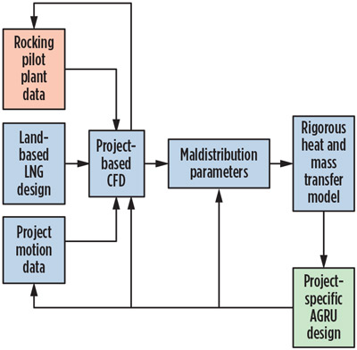
Although acid gas removal from natural gas using amines is a mature and widely used technology in the LNG industry, the use of amine processes for FLNG service has raised concerns with respect to the effect of sea motion on column performance to meet the 50-ppmv CO2 product specification. Therefore, depending on sea motion conditions, significant design margins must be added to the solvent circulation rate and equipment sizes, which will result in a negative impact on the amine unit size, weight and cost. This can be mitigated by conducting detailed marinization studies that include sophisticated computer simulations via a computational fluid dynamics (CFD) model to determine the proper design margins.3
Fig. 4 shows the marinization procedure covering the evaluation of the relevant motions and CFD studies for calculating maldistribution of the scrubbing liquid under the prevailing conditions. Based on this approach, a marinized AGRU design was successfully commercialized in 2017 for the first operating FLNG facility, Petronas’ FLNG1.
 |
|
Fig. 4. Marinization process methodology for optimal design of an offshore AGRU.3 |
The use of membrane technology for acid gas removal from the feed natural gas can be an appropriate solution in offshore applications. Membrane separation, which offers several advantages compared to an amine unit (i.e., greater turndown capability, reduced installation costs, weight and plot space, and insensitivity to rocking motion or static tilt conditions) is suitable only for bulk CO2 removal, where further treating with amine is required to meet the H2S, CO2 and RSH specifications, which will also add significant complexity and cost.
Membranes require a suitable pretreatment system to remove particulates and to avoid liquid formation in the membranes. Improper pretreatment generally leads to performance decline rather than complete nonperformance. The main limitation of membrane systems is the significant loss of hydrocarbons in the permeate stream. This is partly due to the relatively large membrane surface area that is required to reach a 50-ppm CO2 specification. Membrane systems perform well at reduced feed flowrates (from 1 MMsft3d–1,000 MMsft3d), but their performance drops when design flowrates are exceeded. In this case, additional modules must be added in parallel to accept higher flowrates.
In some cases, a hybrid membrane/amine system, which is a combination of membranes for bulk CO2 removal and an amine unit for polishing, will be the best option. A hybrid system can reduce the size and weight of the total pretreatment unit, minimize the effect of sea motion on the amine column performance and offer a cost-effective AGRU solution.4
A detailed configuration study was conducted3 to evaluate different acid gas removal technologies. The amine-only configuration was found generally economically feasible up to 20 mol% CO2 concentration. This threshold may vary from project to project, as it is also influenced by such factors as feed gas flowrate and design rocking motion requirements, as well as waste heat availability in the entire FLNG facility. Above the threshold CO2 concentration, the hybrid configuration offers significant space, weight and capital cost advantages over standalone amine units. For acid gas concentrations below approximately 2 mol%, a solvent-free pretreatment system should be considered. This is described in the integrated pretreatment section later in this paper.
Water and mercaptans removal. Molecular sieves are used to dry the gas leaving the AGRU to below 1 ppmv to avoid hydrate formation and freezing in the cryogenic section of the FLNG facility. They can also be used for the removal of mercaptans and other sulfur compounds to meet a total sulfur product specification of 10 ppm or lower. Molecular sieve units, if properly designed, can economically handle only feed gases containing maximum RSH of 1,500 ppmv.5
While moisture removal is traditionally done with smaller-pore-sized 3A and 4A molecular sieves, mercaptans/sulfur removal is done with larger-pored 5A and 13X types. The 5A type molecular sieve is used for removal of light mercaptans (C1/C2-SH) and trace removal of H2S, while the 13X molecular sieve is used for adsorption of heavy/branched mercaptans. However, co-adsorption on 13X molecular sieves of benzene, toluene, ethylbenzene and xylene (BTEX) components, with concentrations higher than 30 ppmv, will result in increased length of the molecular sieve bed. These components can also cause separation problems in the physical absorption process used to recover the mercaptan species from the spent regeneration gas.
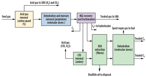
The practical solution for such purposes is to use 5A molecular sieves for removing light mercaptans in the gas phase, as this product has no capacity for BTEX. The heavier mercaptans are then removed with the liquefied petroleum gas (LPG) and condensate (C5+) cuts, which may be further treated downstream using a caustic scrubber process (such as the Merox process, shown in Fig. 5), followed by an MSU to dry the treated liquids to meet required product specifications.
 |
|
Fig. 5. Typical integrated LNG pretreatment scheme with liquid-phase mercaptans removal. |
To optimize the size and improve the performance of the molecular sieve units in FLNG projects, various techniques have been developed in recent years. For example, using multi-layer bed configurations of dense molecular sieves of different sizes can reduce bed voidage and vessel volume. Use of high-quality molecular sieves with superior properties and improved regeneration methods can extend product life and improve reliability, while also providing cost savings.
Mercury removal. The removal of mercury from the feed gas is required to avoid the risk of stress cracking in the aluminum heat exchangers, which are utilized in the cryogenic section of the FLNG facility. Mercury can be removed using non-regenerative metal-sulfide sorbents or regenerative metal-impregnated molecular sieves.
A mercury removal unit can be positioned upstream or downstream of an AGRU. Installing vessel(s) of non-regenerative sorbents upstream of an AGRU normally ensures no mercury contamination through the rest of the FLNG facility. Compared to regenerative systems, it is a simple and conservative approach for handling mercury in the feed gas, since no regeneration equipment is required. Installing a non-regenerative mercury removal sorbent downstream of the AGRU, just before the MSU, reduces the size of the molecular sieve beds to some extent, but poses the risk of mercury contamination of the AGRU solvent system.
Adding a regenerative, metal-impregnated mercury sieve section to the molecular sieve beds allows for the simultaneous removal of water, mercaptans and mercury. It also provides the option of having a potentially longer service life and eliminating pressure drop from having a non-regenerative adsorber. However, this option may require a separate vessel of non-regenerative metal sulfide adsorbent for treating relatively high mercury content in the regeneration water, which would result in additional costs.
NGL recovery/heavy hydrocarbons removal. Removal of NGL from the gas to be liquefied is necessary to avoid waxing and plugging in the main cryogenic heat exchanger.
The usual solution is to use a scrub column ahead of the liquefaction unit, operating at liquefaction pressure and thermally integrated with the cryogenic heat exchanger. Although this method has been widely used, it has limitations in terms of inlet feed gas operating pressure and composition. In fact, a reduction in the scrub column pressure to below the critical point may be necessary, resulting in reduced liquefaction efficiency and increased power consumption. In addition, when the gas becomes lean in C2 or C3+, it is difficult for the column to operate stably and efficiently due to insufficient liquid reflux in the column.
An alternative to using a scrub column is to use an NGL recovery unit to recover the C2+ or C3+ hydrocarbons from the treated/dried gas. Conventional turboexpander technology can be used to produce a lean gas for liquefaction to comply with LNG product specifications. Although propane and butane pose no freezing problem, they are removed together with the heavy hydrocarbons and can be separated and sold as liquid products. In addition, the extracted ethane is returned to the natural gas stream, used as refrigerant makeup or used to supplement the fuel gas.
Although a front-end NGL recovery unit utilizing conventional turboexpander technology can handle a wide variety of feed gas compositions and effectively remove HHCs, it contains rotating equipment that impacts the capital investment and reliability of the FLNG facility. Today’s proprietary NGL recovery processes may reduce capital costs through the use of high-efficiency expanders/compressors and compact heat exchangers; however, they may prove difficult and complex to operate. For these reasons, these processes may be less desirable for most FLNG facilities that prefer operational simplicity and minimum maintenance designs.
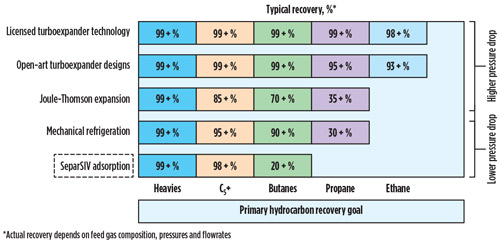
Several technologies on the market can effectively remove HHCs if the feed gas is rich (Fig. 6). When feed gas is lean, meaning less than 2 gal of C2+ NGL/1,000 ft3 (GPM) of feed gas, traditional methods (such as scrub columns, expansion and condensation) tend to be either non-economic or difficult to operate.2
 |
|
Fig. 6. Heavy hydrocarbons removal options.6 |
In response to these challenges, a flexible, proprietary C5+ HHC removal solution was developed for projects utilizing lean gas feed. It is a highly selective, multilayer, adsorbent-based thermal swing adsorption (TSA) system that removes the C5+ fraction, while leaving behind the C4– fraction in the LNG product for Btu heating value (Fig. 7). The technology is an energy-efficient process because it avoids the significant reductions in pressure drop and cooling load typically experienced with cryogenic options. In addition, only the regeneration gas is cooled to precipitate the HHCs. This can reduce compression and/or cooling load, which can result in significant cost savings.6
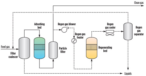 |
|
Fig. 7. Proprietary heavy hydrocarbons removal process.2 |
Integrated pretreatment schemes. Commercial gas pretreatment technologies, like those discussed in this article, can be integrated and configured into various FLNG pretreatment schemes, each offering unique benefits. In an integrated treating scheme, the main objective is to achieve an optimized, compact solution that can provide great process flexibility with varying feed gas conditions. Additional objectives include easy scalability based on feed gas impurity concentrations and flowrates, safety and systems reliability, and significant energy and capital cost savings.
For acid gas concentrations below 2% and with feed flow capacities up to approximately 250 MMsft3d, a simple and cost-effective “all-in-one” adsorption process has been developed for LNG pretreatment. This proprietary, two-stage process eliminates the need for an amine unit and liquid solvents. The combined TSA and pressure and thermal swing adsorption (PTSA) system meets LNG specifications for CO2, H2S, RSH and H2O, and selectively removes C5+ hydrocarbons and BTEX (Fig. 8). The process is based on proven technology that selectively removes impurities through a unique combination of adsorbents and a comprehensive control system.
In the all-in-one process, feed gas is first fed to the TSA process unit, in which the impurities are adsorbed at low temperatures in a fixed-bed adsorber and desorbed by “swinging” the adsorbers from feed gas temperature (low) to regeneration temperatures (high) with hot regeneration gas. With the proper portfolio of proprietary adsorbents, multiple impurities can be removed simultaneously.
As shown in Fig. 8, water, C8+ hydrocarbons and BTEX can be removed. The treated gas exits the adsorbers and is then filtered and delivered to the PTSA process unit. In this unit, CO2, H2S, RSH and C5–C7 hydrocarbons are removed by the adsorbents and purged by a thermal swing, followed by a pressure swing. The treated gas exits the adsorbers and is then filtered and delivered to the customer’s downstream processes.
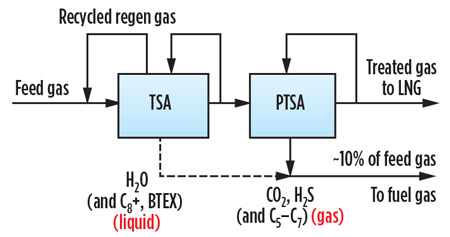 |
|
Fig. 8. Proprietary all-in-one adsorption system. |
An “all-in-one” adsorption system is ideal for FLNG applications. It meets LNG specifications for acid gas, water and C5+ HHC removal without the need for an amine unit, which saves weight and plot space; and with very little pressure drop, which saves compression or cooling load. Regeneration purge gas is minimized by the PTSA to approximately 10% of the feed flowrate, which can be used for onsite fuel gas.
Takeaway. A key step in the development of an attractive FLNG solution is the selection of an appropriate gas pretreatment system that best meets the project objectives. Several technology options can be integrated into the design of the gas pretreatment section of FLNG projects. When determining the optimal integrated pretreatment scheme, simplicity, safety, weight, cost, reliability and operational flexibility must be considered. GP
LITERATURE CITED
- Festen, L., J. Leo and R. Vis, “CB&I Lummus and Partners to Turn LNG FPSO concept into a reality,” LNG Journal, September 2009.
- Smith, T. and S. Doong, “Selective C5+ removal for lean feed gas,” LNG Industry, February 2016.
- Kayat, Z., D. Farr, S. Doong, R. Subris and M. Schott, “Pretreatment of acid gas in feed for Petronas floating LNG facility,” 25th World Gas Conference, Kuala Lumpur, Malaysia, June 4–8, 2012.
- Acikgoz, S. U., L. Zhou, S. Doong and P. Chen, “Offshore gas treatment technology for natural gas,” 2012 AIChE Spring National Meeting, Houston, Texas, April 1–5, 2012.
- Mokhatab, S. and P. Hawes, “Optimal mercaptans removal solution in gas processing plants,” GPA Europe Spring Technical Conference, Hamburg, Germany, April 22–24, 2015.
- Smith, T. and R. Palla, “Pretreatment improvements,” LNG Industry, December 2016.
 |
Saeid Mokhatab is a world-class expert in the natural gas processing industry who has been actively involved in different aspects of several large-scale gas processing projects, from conceptual design through plant startup and operations support. He has presented on gas processing technologies worldwide and has published 300 technical papers and two handbooks, which are widely read and highly respected.
 |
Shain Doong is the Senior Manager of the Gas Processing and Hydrogen Development Group at Honeywell UOP in the US. He has worked with UOP for 12 yr. Previously, he worked for ExxonMobil, BOC Gases and the Gas Technology Institute. His background is in gas separation and purification, with focuses on adsorption, membrane and solvent processes.
 |
Raj Palla is a Senior Business Development Manager for Honeywell UOP’s gas processing division in the US. He has been with UOP since 2006, working in business development and technical sales support activities for various gas processing technologies. Mr. Palla has participated in and directed research projects in sub-quality gas upgrading, gas treating, gas dehydration, gas-liquid membranes and H2S scavenging. He is the author/coauthor of a number of presentations and articles and holds seven US patents.
 |
Trevor Smith is Senior Product Line Manager for Honeywell UOP’s gas processing and hydrogen business unit in the US. He has been with UOP since 2014, managing licensed technology and equipment offers for natural gas and liquid hydrocarbon treatment for LNG and petrochemical applications. Previously, he managed unconventional gas research and training programs at the Gas Technology Institute.


Comments