
Efficiency improvements in liquefaction using vortex feed gas precooling
In today’s competitive energy environment, low-cost LNG from North America, the Middle East and Russia/CIS is the most economic way for energy-disadvantaged countries and remote areas throughout the world to reduce their dependency on higher-cost and dirtier fossil fuels. LNG terminals have been around in various capacities for decades, with only incremental improvements in the technology.
These facilities require significant energy consumption in the refrigeration/liquefaction process to bring gas temperatures to cryogenic liquid levels. Using its existing proprietary technology, one company has developed a solution to reduce the energy required to make LNG by up to 62%, using the available pressure differential off the incoming gas transmission line to cool the incoming gas stream.
Natural gas conversion to LNG takes place at a gas temperature of –260°F (–162°C) and a pressure of approximately 4 psig (0.28 bar). The large energy consumption associated with LNG production can be substantially reduced by placing the LNG plant in close proximity to a pipeline pressure letdown facility (e.g., gate station or wellhead) and utilizing the available cooling load (Joule-Thomson temperature drop of the pressure-regulated main pipeline gas flow) to precool the LNG feed before it enters the battery limits of the LNG plant.
Technology approach. Conventionally, the practical application of this cooling load is complicated by the possibility of the depressurized gas turning a standard pressure regulator into an “ice ball,” restricting flow. The core technology eliminates this obstacle by securing a non-freeze pressure reduction of non-dried, non-preheated gas.
The core of the approach is a proprietary vortex tube that does not freeze because it is self-heating. The vortex tube performs as a pressure regulator of the main pipeline gas flow, or a portion of the main flow, where the vortex tube, configured as a dual-stream (hot/cold outlets) unit, chills the LNG plant’s feed gas, using the vortex cold outlet flow. The gas temperature has been reduced by both the Joule-Thomson and vortex phenomenon. The self-heating vortex solution has been implemented in more than 4,000 installations globally across the natural gas industry, from wellheads to conventional pressure regulation stations (PRSs), farm taps, and in CNG cooling and pressure reduction.
The vortex tube in Fig. 1 is a custom cylindrical device with no moving parts. In the tube, the high-pressure gas expands in the tangential inlet nozzles down to the delivery pressure. While in the vortex tube’s cylindrical section, the rotating, low-pressure gas undergoes energy division (vortex phenomenon), forming two currents: the cold, located in the tube’s center, and the hot, at the unit’s periphery close to the vortex tube’s walls. The cold and hot currents exit the vortex tube separately via the cold and hot outlets. The patented self-heating (non-freeze) vortex tube has been in service in the natural gas industry for nearly 20 yr.
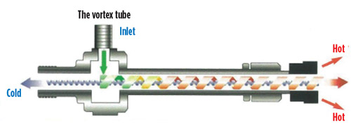 |
| Fig. 1. Proprietary dual-flow self-heating vortex tube. |
In the self-heating vortex tube, the hot gas is used to warm the unit inlet nozzles (spot heating) prior to exiting the tube, thereby eliminating the likelihood of depressurizing gas freezing (self-heating provision). This provision makes the vortex tube technology unique among vortex devices.
The intensity of the vortex energy division is roughly proportional to the ratio of the vortex tube inlet and outlet pressures and is unaffected by the gas flowrate through the unit. The actual temperatures of the vortex tube cold and hot outlet are expressed as shown in Eqs. 1 and 2:
T cold = T inlet – ∆T Joule-Thomson – ∆T (vortex, cold) (1)
T hot = T inlet – ∆T Joule-Thomson + ∆T (vortex, hot) (2)
A valve at the tube’s hot outlet is used to set a desirable ratio between the tube cold and hot outputs to fine-tune the vortex cooling load to maximize the net effect.
The self-heating vortex tube provides for efficient phase separation in the non-dried vortex inlet gas flow. Water/hydrocarbon droplets, which either enter a tube with inlet gas or condense in the tube’s central, low-energy (cooled) area, are coalesced in a highly turbulent vortex flow and are then separated (centrifuged) at the vortex tube hot periphery to evaporate. Therefore, the vortex tube cold outlet exits the tube as a one-phase flow, dried to a low dewpoint; the tube’s hot outlet in pipeline applications is, generally, also a single-phase stream. However, in vortex LNG feed precooled wellhead applications, the tube’s hot outlet may still carry some liquid hydrocarbons and water, and therefore shall be phase separated.
A conceptual flow diagram of the vortex LNG feed precooling system at a typical city gate with typical flow and pressure parameters is shown in Fig. 2. In this arrangement, the vortex flow is a portion of the total pipeline gas flowrate. The self-heating vortex tube performance characteristics are calculated by UVI.
 |
| Fig. 2. Vortex LNG feed precooling system conceptual flow diagram. |
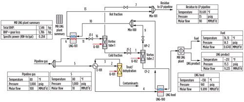
Single-stage LNG feed gas precooling. A hydrological process simulation of the proprietary vortex LNG feed precooling system at a city gate, utilizing the available gas pressure differential, is shown in Fig. 3.
 |
|
Fig. 3. Vortex LNG feed precooling system simulation at a city gate station. |
The self-heating vortex tube in Fig. 3 operates as a primary pressure regulator under inlet and outlet pressures of 1,000 psi and 45 psi, respectively, and is designed for a flowrate of 90 MMsft3h (9/10 of the total PRS flow capacity). The tube is set to split its inlet flow into a 60% (cold outlet) to 40% (hot outlet) proportion; this split produces the greatest possible vortex cooling duty. The net “vortex” temperature drop in the tube cold outlet under the aforementioned gas pressures and the established vortex cold/hot flows ratio is 80°F.
With the added Joule-Thomson temperature drop value and the arranged recuperation created in the tube cooling duty, the gas temperature at the tube cold outlet drops as low as –99.6°F (a 179.6°F temperature decrease from the original 80°F), and the LNG feed (10 MMsft3d) heat exchanged with the pressure-regulated PRS gate station gas is chilled to –87°F (–66°C). The –87°F, 1,000-psi gas is directed to the LNG plant.
The net energy efficiency benefit of the vortex LNG feed precooling, which reduces the LNG feed temperature from 80°F to –87°F, can be expressed as follows: –87°F – (–262°F) ÷ 80°F – (–262°F) = 0.51. The energy savings in this case is 100% – 51% = 49%.
Two-stage LNG feed gas precooling. The intensity of energy division in a vortex tube at a fixed value of the inlet gas flow split is proportionate to the vortex tube inlet to outlet gas pressure ratio. However, with a gas pressure ratio increase, the absolute value of the gas temperature increment (added ΔT cold and ΔT hot) steadily decreases.
Therefore, in cases when a large gas pressure differential is available at an application site and the application goal is to maximize the gas temperature drop, it is more beneficial to arrange a two-stage vortex tube operation in which each tube operates under a pressure ratio provided with a high thermal yield. In such an arrangement, the cold outlet of a first-stage tube performs as an inlet to a second-stage tube.
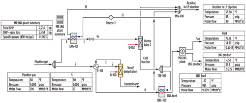
A process simulation of vortex LNG feed precooling at a city gate in a two-stage vortex cooling arrangement, using the outlined case study data, is shown in Fig. 4. In the two-stage scenario, the self-heating vortex tube units, each set up for the 60:40 inlet gas flow split, collectively operate as a primary pressure regulator, reducing gas pressure from 1,000 psi to 200 psi (first stage) and from 200 psi to 45 psi (second stage). The thermally efficient gas pressure ratio of 5, maintained in both stages, provides approximately 60°F of “net” vortex temperature drop in each stage.
 |
|
Fig. 4. Two-stage vortex LNG simulation at a city gate station. |
The total (vortex and Joule-Thomson) two-stage chilling, supplemented with recuperation of the cooling duty, brings the gas temperature of the second vortex tube cold outlet to –155°F (total –235°F gas temperature change from the original 80°F at the inlet). The LNG feed (10 MMsft3d, as in the vortex single-stage case) heat exchanged with the pressure-regulated city gate gas is chilled to –130°F (90°C). Finally, the –130°F, 1,000-psi gas is directed to the LNG plant.
The net energy efficiency of two-stage vortex LNG feed precooling by reducing LNG feed temperature from 80°F to –130°F can be expressed as follows: –130°F – (–262°F) ÷ 80°F – (–262°F) = 0.38, or 62% energy savings. Note: At a PRS inlet gas temperature of less than the 80°F indicated in this model, the LNG feed gas temperature would be proportionally lower.
This vortex solution for decreasing the cost of LNG production can be used at almost any PRS, including wellheads (onshore and offshore), provided that the LNG plant’s feed gas is a fraction of the pipeline’s pressure-regulated gas flow. The system must have a place to dump pressure-reduced gas downstream of the PRS.
In addition to the direct benefit of the vortex LNG feed gas precooling technology, ancillary benefits emerge:
- At a pipeline PRS equipped with a line heater, the vortex LNG feed gas precooling system set up as a bypass of the main gas flow reduces the amount of high-pressure gas to be preheated upstream of pressure regulation.
- At a wellhead with glycol treatment of high-pressure gas, the vortex LNG system reduces the amount of inhibitor injected into the gas.
Utilizing the vortex LNG feed gas precooling technology, operators can significantly reduce the cost of their plants (on a per-ton of LNG product basis) due to the reduced amount of chilling needed, thereby increasing the economic viability of such projects. For new plant applications, this will result in decreased costs for the liquefaction train design due to the smaller temperature drop required to reach the critical –262°F LNG temperature, or result in increased throughput/liquefaction capacity if all else is kept equal.
Fully scalable, this technology can be applied to micro-LNG systems, mini-LNG, peakshaving and world-scale export LNG plants. The only limiting factor of the technology is the availability of a downstream outlet for “hot” pressure-reduced gas.
The vortex LNG feed gas precooling system has obvious economic and environmental impact benefits to any applicable natural gas liquefaction project. In today’s competitive market, all substantial economic and environmental improvements should be considered for any new project or retrofit. A vortex LNG adaptation to existing plants, or as an addition to a new project, is sure to offer measurable returns to the liquefaction plant. GP
 |
Lev Tunkel graduated from the Moscow Oil and Gas University in Moscow, Russia with an MS degree in mechanical engineering and a PhD in fluid mechanics. He has more than 30 yr of experience in research and development, process design, and engineering in gas production and gas transmission operations. He pioneered the applications of the vortex phenomena for thermal conditioning of natural gas and other industrial process gases. Dr. Tunkel has served as Technical Director of Universal Vortex Inc. since its inception. He has substantially contributed to refining the existing vortex phenomena applications and to the development of a new concept of energy saving and “green” vortex CNG and LNG technologies, as well as non-freeze vortex pressure reducers and vortex heaters. Dr. Tunkel holds more than 20 Russian and US patents in the field, with publications in major professional magazines published in Russia and the US.
 |
Ross Gale has served as the Director of Global Sales and Marketing at Universal Vortex Inc. (UVI) since 2015. Tasked with growing a small startup natural gas technology firm into a world-known company with widely used solutions, Mr. Gale has overseen the expansion of UVI’s customer base across six continents, serving nearly 4,000 projects worldwide in just 4 yr. Since mid-2018, he has led the commercial development plan for implementing UVI’s VortexLNG Feed Gas Precooling System. Mr. Gale has been invited to speak on behalf of UVI at technological and commercial events in the gas industry worldwide. He comes from an entrepreneurial international business background, having served as the Director of Acquisitions for a multinational industrial equipment company. He holds a degree in business management from Babson College in Wellesley, Massachusetts.


Comments