
Case studies of troubleshooting amine treating foaming—Part 1
Amine solution foaming is a phenomenon that has been intensively studied and reported. Several foaming root causes have been determined throughout the years; however, the latest experiments suggest that the predominant mechanism for foaming is related to contaminants in the form of surface-active materials, or surfactants.
These contaminants can enter the unit in solid, liquid or gas phases and often modify the solution properties in such a way that foam (in gas contactors) and emulsions (in liquid-liquid treaters) are produced, leading to a series of negative effects that cause solution losses and hinder the process from meeting specifications. Determining the source of foaming requires thorough investigation of several possible sources.
Following is a list of some of the many contaminants and sources determined to be the root cause of amine foaming:
- Ineffective inlet separation leading to contaminant ingress
- Pipeline chemicals, such as corrosion inhibitors, hydrate inhibitors, fracture fluid organic acids, dispersants, soap sticks, etc.
- Liquids from pigging
- Compressor lubrication oils
- Ingress of gas-phase contaminants carried with the feed gas (such as BTEX)
- Hydrocarbon condensation inside the contactor by not maintaining an appropriate temperature differential between lean amine and inlet gas (or, more accurately, the hydrocarbon dewpoint) when processing heavy hydrocarbon-rich feed gas
- Problems in the activated carbon bed
- Incorrect type of activated carbon (exposed to phosphorous-based activation)
- Spent activated carbon beds releasing contaminants into the outlet stream
- High concentration of suspended solids in the amine
- High soluble iron in the lean amine (resulting in fast and high solids formation in the contactor)
- Problems with the antifoam
- Incorrect antifoam (some antifoams will cause foam)
- Excess antifoam injection (excess antifoam use can, in some cases, stabilize or induce foam)
- Contaminants present in the fresh amine and/or makeup water
- Incompatible filter media or materials of construction
- Cleaning chemicals not properly flushed before filling system with amine.
Since amine foam is stabilized by contamination of one type or another, foaming can be eliminated or greatly reduced in severity and/or frequency if efficient inlet separation is in place upstream of the amine contactor. However, if the amine solution does become contaminated, then a proper amine filtration system and activated carbon adsorption beds are helpful in removing the contaminants.
Using antifoams. Antifoams are commonly used to temporarily control the detrimental effects of foaming; however, the effectiveness of a given antifoam may be limited, depending on the type of antifoam used and where it is injected. Some plants use antifoams on a regular basis, but this could harm the solution and the plant over the long term. Root cause analysis of foaming and the elimination of its source are the best ways to deal with a foaming amine solution. Nevertheless, antifoam may be required when sporadic foaming incidents occur and the source of the foaming agent has not been identified.
When adding antifoam, plant personnel should proceed with caution to keep the unit under control, especially when operating at high production rates. The antifoam will usually separate as a top layer in the unit flash tank, sump or surge tank surface. It also can be removed by certain filters and carbon adsorption beds (for most types of antifoam); therefore, their build-up in the circulating solution can be controlled.
Typical antifoams used in amine service fall into the following categories: silicone-based, silicone esters, polyglycols, high-molecular-weight alcohols and polyalkyl ethoxylates. The correct antifoam for the system is best determined with onsite foam testing. Silicone-based antifoams are perhaps the most effective products, but at the same time they are least chemically compatible with amine solvents.
Field experience in amine unit foaming, testing and troubleshooting are critical factors to better understand the foaming phenomenon, its origins and how to combat its effects. Foaming can be a tricky problem to solve, as it involves investigation into the chemical, operational and design aspects of the unit. In the following case studies, examples are given of how thorough, disciplined reviews of some foaming incidents resulted in mitigation of foaming problems.
Amine foaming Case 1: The foaming CSI. A small amine unit in North America processed gas containing 0.07 mol% hydrogen sulfide (H2S) and 1.6 mol% carbon dioxide (CO2) with a blended MDEA solvent. The plant removed the H2S and CO2 to pipeline specification, and the acid gas was sent to an iron redox unit for complete removal of H2S and, subsequently, zero plant emissions.
Since startup after a plant turnaround, the system experienced foaming episodes that frequently caused carryover of amine to the sales gas scrubber and the occasional regenerator burp of a small amount of amine into the acid gas scrubber upstream of the redox unit. The plant-supplied antifoam appeared to be effective in knocking down the foam when the operator added it to the system. The addition was made to the pump suction of the lean amine charge pumps. The treated H2S gas typically sat at about 1 ppmv–2 ppmv; the treated gas CO2 typically sat at about 1,500 ppmv, both well within the allowable 16-ppmv H2S spec and the 2-mol% CO2 spec.
All foaming episodes could be handled during the day while the operator was onsite, but the plant was left unattended at night, with alarms tied into the operator’s home a few miles away. Invariably, sometime between midnight and 2 AM, the plant would alarm on a low surge drum level, resulting in a frantic drive to the plant to turn on the antifoam pump to again get absorber bottoms returns and subsequent flow to the almost-empty surge drum. A few problems with handling the large influx of liquids in the absorber sump and flash drum were observed, but careful monitoring and control helped the plant get back on line.
After spending an hour or so to check that the plant had levelled out, the operator went home to try to get a couple hours of sleep before heading back to the plant at 6 AM. After weeks of interrupted sleep, the operator came up with the only solution that made sense to him—install a surge drum with twice the fluid capacity as the original drum. So, the larger tank was ordered.
After installation and hookup of the new, larger surge drum, the operator was pleased at no more alarms in the middle of the night. He confidently drove to the plant site to turn on the antifoam pump, as the amine was again hung up in the absorber. However, with the larger volume of amine now in the column, the antifoam addition resulted in such a large mass of liquid crashing to the absorber bottoms that it overwhelmed the absorber and flash drum level control valves. This sent a wave of amine through the acid gas scrubber and into the redox unit.
The event was catastrophic for the acid gas cleanup unit, resulting in an emergency plant shutdown to clean up and replace the contaminated inventory. What appeared to be an ingenious solution to the aggravating foaming problem turned out to be the genesis of a worst-case scenario event. Management was not pleased with the cost of replacement inventory and the lost production, and strongly suggested to the operator that he seek outside technical support to solve the foaming issues.
Root causes. Evaluation of the contactor showed that the vapor capacity was not being exceeded; this would have resulted in high entrainment and carryover, resembling foaming. Simulations showed that the tower was operating at approximately 50% of flood. Assuming no internals damage, the hangup and carryover events did not appear to be caused by mechanical limitations. The lean amine temperature was warmer than the feed gas temperature to ensure that hydrocarbons were not being condensed in the column, leading to a higher foaming tendency. All system temperatures checked out, with the lean amine consistently operating 5°C–10°C (8°F–15°F) warmer than the feed gas.
Carryover of inlet separator fluids is often the main cause of plant foaming episodes. No sign indicated that any significant carryover of fluids was occurring; the large separator collected bulk fluids, and the upper chamber of the vertical coalescer dumped regularly. During the evening foaming events, there was some amine loss to the scrubber upstream of the ethylene glycol (EG) refrigeration plant, leading to a small amine level in the analyzed EG solution. If possible, the captured amine was returned to the system flash drum, and makeup amine was added. Consumption of amine was higher than in the past, but not enough to raise alarms with either operations or management.
To successfully solve a foaming event, it is necessary to understand the sequence of smaller events that led up to the eventual large event, including:
- Was there a foaming trigger point, and was this the same trigger point in every foaming event?
- In what order did the following events occur?
- Differential pressure increase
- H2S increase in treated gas (discussed in more detail later)
- Loss of bottoms level
- Low-level surge drum alarm
- Carryover of amine
- Is there a pattern to the sequence that will allow for a more rapid recognition and response?
- Temperature profiles in the contactor before and during the foaming event.
A review of the vendor lab results showed, as expected, that for the relatively new solvent and frequent solution makeup requirements, the solvent appeared to be in good chemical condition [appearance was pale straw color, heat-stable salts (HSS) were low, solution was well regenerated, and there were no visible solids, cloudiness or hydrocarbon layer].
To solve foaming problems, samples should be gathered of any possible process fluid or contaminant stream that could enter the amine unit, with the purpose of running a series of foam tests. These samples usually include lean and rich amine, makeup water, reflux water, storage tank amine, and potential contaminants like inlet separator or sweet gas knockout fluids. Depending on the foam test results, fluids may be eliminated as a source of foaming, or definite problem fluids may need to be controlled, cleaned or replaced.
The plant had differential pressure gauges on both the absorber and regenerator, which appeared to be reading accurately (based on the number of trays and liquid load in the column, and when compared to simulator-predicted values). The plant also had a treated gas analyzer that measured both the sales gas H2S and CO2, which turned out to be one of the most valuable tools for subsequent foam prevention in the unit. Level control valves appeared to recognize the loss of bottoms level and respond properly to foaming episodes. The flash gas rate off the flash drum was not measured, but the pressure of the flash drum did respond to what appeared to be higher flash gas rates.
The first observed sign of foaming was a slight closing of the absorber level control valve to re-establish the setpoint level, with some indication of the flash drum pressure increase. The second sign was a sharp decline in treated gas CO2. The third sign was a bounce in the differential pressure (dP) measurement. The fourth sign was a gradual increase in treated gas H2S. The fifth sign was elevated dP and indication of carryover in the downstream knockout drum.
The recommended plant corrective action for antifoam addition was to wait for the treated gas H2S to hit 4 ppmv (on a 16-ppmv specification) to shot-dose the system with antifoam. Historically, it took about 10 min–15 min for the H2S to move from 4 ppmv to 16 ppmv in the treated gas. To avoid adding antifoam for the day-to-day excursions to 2 ppmv–3 ppmv H2S in the sales gas, 4 ppmv was chosen as the appropriate value for antifoam addition.
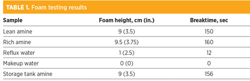
The 4-ppmv target was also early enough in the foaming cycle that a manageable amount of amine would be hung up in the absorber column. This response required trust in the efficacy of the antifoam product to handle the foaming condition. Up until the site visit, it had proven effective. Table 1 shows the foam tests performed on the solutions in the system and the results.
 |
Normally, samples of non-foaming storage tank amine would have been used as a comparative baseline to test against the change in foaming tendency between the fresh baseline sample and the sample after the addition of other possible contaminants, including feed separator fluids, reflux water, makeup water, treated gas knockout drum fluids, etc.
However, the initial test results showed that the storage tank amine was the most likely cause of the system foaming episodes. A small contribution may have come from inlet carryover, and the lean-side carbon bed appeared to help marginally in reducing the foam. Ultimately, however, the most problematic amine appeared to come from the fresh storage tank. The surfactant did not appear to be volatile, as the reflux water did not exhibit a high foam height or stability. Subsequent mix tests were not attempted.
Fresh storage tank amine foam investigation. If the fresh amine foams badly, the usual causes fall into two basic considerations:
- Pre-existing contamination in the storage tank
- Contaminated product shipped from the vendor.
Prior to the turnaround, the storage tank was supplied with the initial charge of amine and assumed to be clean, although no corroborating data could be found. Performance of the amine system prior to the shutdown showed normal occasional foaming episodes—most likely related to feed contaminant ingress—but no persistent foaming, as noted after the turnaround.
During the turnaround, fresh amine was purchased to top up the storage tank for the next production run. It was this blend of the original tank residue and the fresh charge that showed high foaming tendency and severe foaming stability. Considering the lack of foaming from the original load of amine in the plant, it was assumed that the contamination was not pre-existing in the storage tank. That meant that the most recent shipment of amine was contaminated with a surfactant that gave the amine a stable foaming condition and that caused significant hangup in the contactor, loss of levels in the system and, ultimately, the carryover of amine into the downstream ethylene glycol refrigeration process. Fortunately, the plant had an excellent antifoam that could control the foaming when added.
To determine the contaminant in the amine, the retention sample from the last amine shipment was tested. It is recommended to always take and store a retention sample from any amine shipment to ensure that the product can be re-tested if problems arise due to the quality of the amine. Unfortunately, the plant did not take a retention sample.
The vendor, as required, had retained the shipment sample for the facility. It was analyzed for composition, contaminants and foam testing, and found to have no foaming tendency and to be in excellent chemical condition. That result was expected (because vendors test their shipments for these very issues), but it now eliminated what was considered the answer to the problem.
That left the one final link in the shipment—the truck—as the only viable contaminant source. The truck driver was tracked down for questioning. It was determined that, prior to delivering the amine to the plant, the driver had delivered a shipment of corrosion inhibitor to another facility. Since certain components of corrosion inhibitors can cause severe foaming in amines, the investigation was furthered via discussions with the corrosion inhibitor manufacturer. A sample of the inhibitor was obtained and foam-tested with fresh amine. The sample was found to cause an aggressive, stable foam in the vendor retention sample. The “smoking gun” had been found.
Now that the cause of the foaming had been determined, the storage tank sample needed to be tested for the inhibitor. The corrosion inhibitor vendor graciously offered to conduct comparative gas chromatography–mass spectrometry (GC–MS) runs with its product and the storage tank amine. Residual corrosion inhibitor was indeed found in the sample, but only at a few-ppm strength. It was assumed that this would not have been enough to raise the kind of foaming tendency and stability seen in the plant sample. Via dilutions with micro-syringes, a reasonably low residual ppm inhibitor level was reached in a clean amine solution and then foam-tested.
The foam tendency and stability mirrored the actual foam tests on the storage sample. The cause of the foaming was determined to be the trucker’s failure to sufficiently clean the inhibitor residue from the truck prior to reloading with amine. However, the trucker kept meticulous records, including tank cleaning steps between loads. The records were reviewed, and the cleaning steps were found to be as good as can be expected; two water flushes, a steam-out and a final steam condensate flush.
How had a clean delivery truck managed to ship contaminated product to the plant? The final puzzle piece fell into place when further discussions with the driver revealed that he had never cleaned the hose used to transfer product from the truck to the storage tank. The corrosion inhibitor, being a heavy surfactant, had clung to the inside of the hose and when the amine flowed through it, some of the residue in the hose was picked up and transferred into the storage tank. An entire plant shutdown had occurred due to foaming caused by a contaminated 50-ft (15-m) length of hose!
Solutions and mitigations. Several takeaways from the investigation were used to ensure future smooth operation of the facility. The plant purchased a dedicated amine hose to be used for all transfer of product from the delivery truck to the plant storage facility. It would no longer rely on a potentially contaminated hose.
Plant personnel would also take and store a retention sample of the latest amine delivery. They asked the vendor to run a quick foam test on any product shipped to the plant so that the non-foaming tendency of the product prior to delivery would be confirmed. The plant also instituted a policy that delivery trucks were not to have shipped potential surfactants prior to amine shipment. Dedicated amine and glycol trucks became the new norm. Plant personnel now run monthly foam tests to ensure that the incumbent antifoam still works to kill the foaming tendency and stability of the foam.
Most importantly, the plant now uses a different indicator for antifoam injection. In the past, the plant would wait for the H2S to creep from 1 ppmv to 4 ppmv in the sales gas before adding antifoam. This usually occurred about 15 min after the first sign of foaming in the system—i.e., a variation in the absorber dP measurement, a slight closing of the absorber level control valve, a hint of extra flash gas, etc. This procedure had not given the operator much of a window to walk out to the antifoam pump, turn it on and hope the product made its way to the absorber in time to prevent the gas going off-spec (12-ppmv alarm on 16 ppmv allowable).
Since the plant also measured CO2 in the sales gas and it reacted much quicker to CO2 than to the tower differential and H2S, it became the new antifoam addition trigger. Historically, the treated gas CO2 would average 1,500 ppm but drop to around 600 ppm as the amine foamed. [Note: A foaming methyl diethanolamine (MDEA) will absorb more CO2 than a non-foaming MDEA, because CO2 absorption is liquid-phase dependent and the added amine hung up in the column was reacting with the CO2].
At 1,000 ppm CO2 in the treated gas, about 5 min after the first signs of foaming, the antifoam pump was turned on automatically. This quicker response time meant far less hangup and no occurrences where the system approached going off-spec on H2S. By hooking up the pump to inject automatically, it also took away from the operator’s poor response time if business was being conducted in another part of the plant.
Takeaway. This foaming story was memorable because of the level of investigation involving three separate companies and the in-depth analytical support and full cooperation from all parties involved.
The willingness of the inhibitor vendor to help in the investigation, and the trucking company’s willingness to release its records, made for a successful conclusion to the mystery. It also conveyed the recognition that contaminants can come from many different sources and that it may only take ppm levels of contaminants to make amine foam. A major event, such as inlet separator carryover, does not always cause an amine to foam uncontrollably.
A multitude of factors can cause an amine unit to experience foam. Only in some cases is a single factor the main cause leading to foaming; often, several items contribute to foaming. One of the most important factors in foam promotion is inlet contaminants, so contamination control at the unit entry is a critical step for ensuring minimal foaming episodes.
Most of the plants that do not consider this step often fight against foaming in addition to high operating costs, low reliability of equipment, and many other adverse incidents with economic and environmental impacts. Other sources of foaming should be considered, such as operational practices and the materials used within each piece of amine plant equipment. Sometimes the culprits can be found where least expected. Therefore, a comprehensive testing plan, with systematic analysis protocol, should always be performed, not only to determine the cause(s) of foaming but also to form a plan for effective, long-term foaming mitigation.
Part 2 of this article will present a second case study of troubleshooting of an amine unit with foaming problems. GP
 |
David Engel is the Managing Director of Nexo Solutions and Technology Leader for Exion Systems. He has more than 25 yr of industrial experience in a variety of areas of chemical engineering and chemistry, and he specializes in chemical engineering, process optimization and contaminant separation technologies. Dr. Engel holds a BS degree in industrial chemistry, an MS degree in chemistry and a PhD in organic chemistry. He is also 6-Sigma and Project Management certified.
He is President of the American Filtration Society, Southwest Region and a member of GPA Technical Section M. Dr. Engel is also the named inventor in 22 US patents and the author of many technical and scientific papers. He has developed business and technology for Eastman Kodak, Eli Lilly, Pentair, General Electric and Sulphur Experts.
 |
Ben Spooner has been working in the amine industry since 1998 as an operator and engineer. He joined Amine Experts in 2003 and has worked in more than 25 countries and on hundreds of amine systems, providing expert assistance and advice regarding plant operations, troubleshooting, optimization and operator training. Mr. Spooner is one of the primary speakers at Amine Experts’ amine treating seminar, which has been presented in dozens of locations around the globe. Prior to joining Amine Experts, he worked as an operator at a gas processing plant in northern Alberta, and as an engineer in the technical service department of a large amine vendor based out of Edmonton, Alberta.
 |
Michael Sheilan has been involved in the gas processing industry for 39 yr. He has a long history of expertise in training operators and engineers in gas processing, as well as troubleshooting all aspects of upstream gas treating processes. More recently, Mr. Sheilan has focused on dehydration and amine sweetening as a senior staff engineer for both Amine Experts and Dehydration Experts. He is one of the Principal Speakers of Amine Experts’ five-day amine treating and sour water stripping courses, as well as the four-day dehydration course. He has provided technical support to more than 500 facilities on every continent (except Antarctica). Mr. Sheilan is a registered Professional Engineer in Alberta (APEGA) and is a member of the Gas Processors Association of Canada (GPAC) and the National Association of Corrosion Engineers (NACE). He has multiple publications on topics as far-reaching as inlet separation and filtration, amine sweetening, glycol dehydration and sour water stripping.


Comments