
Best practices for design and operation of reboilers with plate-fin BAHXs
Brazed aluminum heat exchangers (BAHXs) are used in cryogenic reboiler applications for natural gas processing and ethylene production. In these applications, plant operating conditions can change constantly due to economic factors or to inlet gas composition. This makes operation of the equipment challenging.
This article outlines best practices and considerations for the design and operation of BAHX reboilers that will help maximize the lifetime of the BAHX and help promote more robust plant operation. Considerations include piping, flow stability and heat exchanger design. A summary and references for operating guidelines are included, and examples of consequences from not following best practices are given.
Heat exchanger function. BAHXs are essential for cryogenic gas processing. Features of BAHX include high strength and high thermal conductivity at cryogenic temperatures, and a high surface-area-to-volume ratio. These features enable close approach temperatures that lead to operational efficiency. Applications include air separation, LNG liquefaction, nitrogen rejection, NGL recovery, propane dehydrogenation and other low-temperature natural gas and petrochemical processes.
 |
|
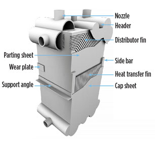
FIG. 1. Basic components of a BAHX. |
BAHXs are constructed of aluminum and consist of layers of corrugated fins and parting sheets that are brazed together. Headers are attached after the block has been brazed to provide fluid communication to the passages. A schematic of a BAHX1 is shown in Fig. 1, with portions cut away so the internal components can be seen. Every BAHX is custom designed for each individual process.2
For many applications, BAHXs are enclosed in a cold box. A cold box is a carbon steel enclosure with flanged terminations. It provides support and an inert atmosphere, houses cryogenic equipment and insulation, and facilitates connection to plant process pipework.
One application of a BAHX is for reboilers in natural gas processing and ethylene processing. A reboiler is a heat exchanger used to boil fluids from a distillation column and circulate the resulting vapor back to the column. A bottoms reboiler refers to a reboiler that processes the liquid from near the bottom of the column. A side reboiler processes the liquid from an intermediate point along the column. A simplified process flow diagram showing the possible locations of reboilers in a natural gas application is given in Fig. 2. In this case, it is a common practice to combine the bottoms and side into a single exchanger block. The piping highlighted in teal in Fig. 2 is the liquid downcomer piping, and the riser return piping is highlighted in grey.
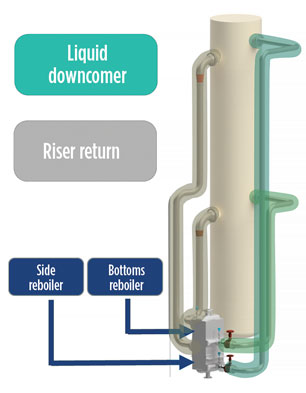 |
| FIG. 2. Simplified diagram showing the possible locations of reboilers in a natural gas application. |
Another type of proprietary reboilera (Fig. 3) consists of one or more BAHX blocks inside a steel vessel. The warm stream enters the left side of the vessel and cools as it passes through the heat exchanger. The cold stream enters the vessel as liquid (or partially liquid), and a liquid level is formed outside the exchanger to create a liquid head that drives the cold stream through the core, where it vaporizes. The cold stream vapor exits through the outlet nozzles in the top of the vessel while the liquid falls back to be recirculated.
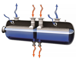 |
| FIG. 3. In this reboiler, the external vessel houses one or more plate-fin heat exchangers. |
These reboilers are used to handle high process flowrates as the cold stream flows cross-currently through the exchanger, and are commonly used in ethylene applications. The reboiler enables approach temperatures as close as 1°C, and they are typically 20% of the size of a comparable shell-and-tube exchanger.
Reboiler best practices and considerations. Too much piping pressure drop can prevent the desired flowrate from being achieved and can make startup more difficult. Piping should be simplified to minimize piping pressure drop and avoid unstable two-phase flow.3 Short-run, direct-connect piping should be used between the heat exchanger and the column. A minimum pressure drop in the reboiler loop is required for flow stability and is best achieved using pressure drop in the heat exchanger and in the inlet control valve, as specified later in this article.
Design for “no pocket” piping. Examples of pockets are shown in Fig. 4. Pockets can contribute to unstable flow and inhibit the drainability of the process. All streams should be drainable and free-drain away from the heat exchanger. An easily drainable design allows for a more efficient turnaround and troubleshooting if the heat exchanger requires service.
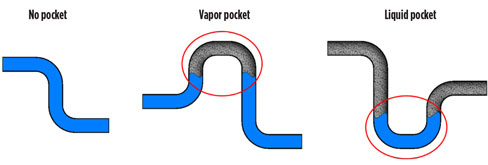 |
| FIG. 4. No pocket and pocketed piping. |
A column liquid outlet nozzle leading to a reboiler should be sized for “self-venting” so that vapor is not entrained along with the liquid entering the reboiler. Excessive vapor entrainment can inhibit reboiler flow since the driving force for flow is from the density difference in the inlet piping, compared to the riser return. Air bubbles can rise when the Froude number is ≤ 0.3, as shown in Eq. 1:4
![]() (1)
(1)
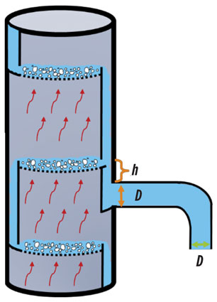
where Fr is the Froude number (dimensionless parameter), ul is the liquid velocity, D is the inside pipe diameter and g is the gravitational constant. The minimum liquid height above the nozzle to prevent vapor entrainment is shown in Eq. 2:5
![]() (2)
(2)
where h is the liquid height above the nozzle. The locations referenced in the equations are shown in Fig. 5.
 |
| FIG. 5. Reference positions and pipe diameters in the distillation column. |
The return line column nozzle elevation should be chosen to match the returning fluid temperature to that of the column. This will result in the return line column nozzle elevation being below the column liquid inlet nozzle, as shown in Fig. 6.
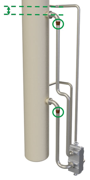 |
| FIG. 6. Reboiler piping showing riser return expansion and column nozzle locations. |
Flow from the riser return back into the column can disrupt the column hydraulics if the velocity is too high. It is good practice to include an expansion in the vertical riser just before the elbow to the column nozzle, as shown in Fig. 6. The elbow will disrupt the velocity profile to help prevent flow jetting into the column. Putting the expansion after the elbow could still lead to flow jetting into the column, and putting the expansion too far before the elbow could cause an undesirable flow regime in the vertical riser return piping.
It is recommended to avoid the use of manifolds and complex piping with parallel paths on two-phase streams, such as the riser return. Avoiding exit manifolds helps prevent interdependence between parallel units.
If lift gas is used, it should be injected at the bottom of the riser return piping. Injection upstream of the heat exchanger can cause operational problems or thermal stress issues because it changes the conditions to the heat exchanger.
The calculated pressure drop through the reboiler loop should correspond to the difference in pressure between the nozzles along the tower. The vapor fraction of the riser return will increase with decreasing flowrate for a given heat load. The actual flowrate in the reboiler loop will be whatever is required to satisfy the pressure balance; therefore, thermosiphon flowrate calculations are typically an iterative process. Piping frictional losses should not be neglected, and design cases should be evaluated.
The piping should be sized to avoid undesirable two-phase flow regimes as much as possible, especially for the riser return piping. The chosen flow regime map should be applicable for the specified fluid composition, operating conditions and piping orientation.6 Several commonly used flow regime maps to choose from include those by Baker, Aziz, Hewitt and Roberts, Taitel and Dukler, Heat Transfer Research Inc., and Heat Transfer and Fluid Flow Service. The flow regime map for vertical flow by Owen7 is shown as an example in Fig. 7.
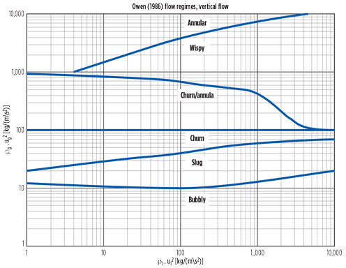 |
| FIG. 7. Example of a flow regime map for vertical flow.7 |
Generally, reducing the size of the vertical piping can help adjust the flow regime from an undesirable slug regime to the annular flow regime, but making the horizontal piping larger helps avoid slug flow in horizontal piping. Avoiding slug flow may entail tolerating a slightly higher pressure drop from using a smaller pipe size for vertical piping on the riser return. In some cases, it is not possible to avoid slug flow across all design conditions.
Flow regime transitions do not occur instantaneously; the borders between regimes are broad, and transition between them is gradual. Some minimum pipe length is required for regimes to change, generally up to 20 pipe diameters or more for a fully established flow regime.
The riser return piping should be broken into < 25 pipe diameter runs, with a short horizontal change in direction, to help alleviate liquid slip so that the homogeneous mixed-phase density is still relevant.
It is good practice to include a low-pressure drop control valve on the liquid inlet piping to the heat exchanger. This assists in promoting flow stability for multiple operating conditions, can help adjust the outlet quality to avoid undesirable flow regimes, and provides liquid shutoff when a loss of feed gas occurs.
If a sudden loss of flow of inlet gas occurs, it is recommended to immediately stop the flow on all exchanger streams to maintain the temperature profile in the heat exchanger and minimize the risk of thermal shock. It may be useful to have a small control valve in parallel with the main control valve for better flow control at low flowrates or during startup. Control valves should be placed just before the exchanger inlet where the flow will be all liquid, and not in the riser return piping where the flow will be two-phase. Control valves must be properly sized to control the flow across the expected range of operating conditions.
Measure and monitor pressure drop across the boiling pass inlet and outlet nozzle of the heat exchanger to assess flow stability. Fig. 8 shows an example of a problem with flow stability when the inlet valve was opened greater than 25%; when the valve was closed below 25%, the flow was again stable.
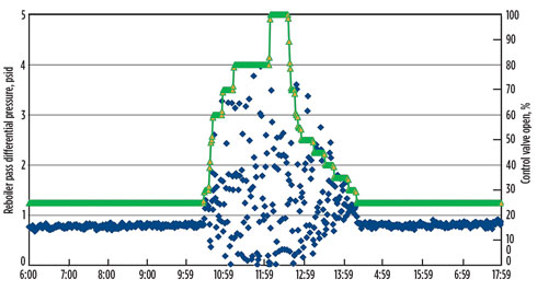 |
| FIG. 8. Example of flow instability with valve % opening. |
A good resource for the minimum required reboiler pressure drop to avoid unstable flow is outlined in the HTFS Handbook.8 It predicts that no instability is likely if the parameter Rp is less than 2. The parameter Rp is defined as shown in Eq. 3:
Rp = (∆P through core + riser return) ÷ (∆P from friction and acceleration of liquid downcomer + inlet control valve) (3)
If the parameter Rp is > 2, then additional assessment must be performed to assess the stability, as outlined in the literature.8
Heat exchanger design. An allowable pressure drop of approximately 1 psi should be specified. Allowing more pressure drop is beneficial to the design of the reboiler for a number of reasons:
- Allows a higher thermally performing fin geometry to be used, which reduces the required size and cost of the heat exchanger
- Helps promote even flow distribution across the heat exchanger width
- Leads to a higher design fluid velocity, which reduces the likelihood of unstable flow in the heat exchanger matrix.
Unstable flow in the heat exchanger matrix can cause high-cycle thermal stresses, which can be detrimental to the operating lifetime of the unit. An example of a flow regime map for the inside of the heat exchanger matrix9 is shown in Fig. 9. Lower vapor and liquid velocities are more likely to lead to unstable intermittent flow.
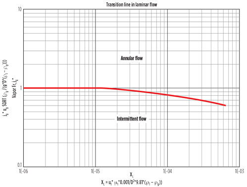 |
| FIG. 9. Example of a flow regime map for the inside of the heat exchanger matrix. |
Combining multiple reboiler services into one block can be advantageous. It can lower cost, reduce the required plant footprint and simplify the piping layout. This can be a cost-effective solution if the plant service is steady. Separating the reboilers into separate units can help reduce thermal stress and increase the lifetime of the unit. This is recommended when plant service changes frequently between significantly different operating cases (such as frequent switching between recovery and rejection modes), especially if one of the reboiler services is turned off.
A new technology and design option for BAHXs. A proprietary, patent-pending technologyb has an inactive outside layer of the BAHX that is capable of withstanding the stream pressure of the outermost active layer. The pressure of this layer is monitored. A diagram of the technologyb is shown in Fig. 10.
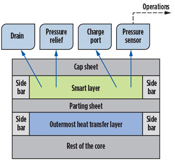 |
| FIG. 10. The layer technologyb provides a method for leak detection and containment of internal leaks until the unit can be repaired or replaced. |
BAHX operation guidelines. Guidelines for operation of BAHXs can be summarized by the phrase: “keep it clean, keep it dry and manage thermal gradients.”
The small channel dimensions that make BAHXs perform so well thermally also make them prone to plugging if fluids are not clean. Strainers should be used to prevent debris from damaging or plugging BAHXs on all BAHX inlets. The recommended size is 177 micron. A strainer with some debris is shown in Fig. 11. A differential pressure gauge can be installed across the strainers to detect plugging. Clean the strainers periodically, especially after startup. Mercury guard beds are recommended for all natural gas streams, even if the inlet gas mercury concentration is below 0.1 μg/Nm3, since gas composition can change over time.2 The use of mercury-tolerant BAHX design features, including different header alloys and header guards, should be considered as additional protection in case of mercury breakthrough past the guard bed.
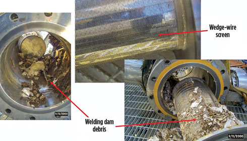 |
| FIG. 11. Strainer with debris. |
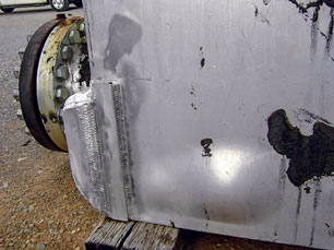
Incoming streams should be removed of water and CO2, which could freeze inside the exchanger at cryogenic temperatures, causing structural damage and leaks. The process piping should be adequately derimed before startup. Fig. 12 shows a BAHX that has been damaged by water freezing internally and expanding, causing a bulge in the cap sheet. The pressure drop of streams through the exchanger should be monitored; a continually rising pressure drop is an indicator of possible ice formation. Actions to consider include warming the exchanger and deriming the system.
 |
|
FIG. 12. BAHX damaged from water freezing internally. |
The most common cause for leaks in BAHXs is cracks from thermal stress. A summary of operating guidelines1 for managing thermal stress are:
- Limit stream-to-stream temperature differences at any axial cross-section to < 50°F (28°C). The temperature locations to compare are shown in Fig. 13.
- Limit cyclical temperature fluctuations to < 1.8°F (1°C/min). These fluctuations refer to regularly occurring variations during operation at steady state.
- Limit stream inlet and outlet temperature rates of change to 108°F (60°C/hr), not to exceed 3.6°F (2°C/min). Applicable scenarios include startup, shutdown, turboexpander or compressor trips, power outages, molsieve regeneration switchover, methanol injections or changing operating cases.
- If a sudden loss of flow in one stream in the BAHX occurs, it is recommended to stop the flow of all streams to maintain the temperature profile in the BAHX and prevent thermal shock.
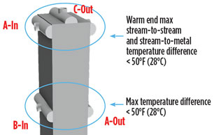 |
| FIG. 13. Stream-to-stream maximum temperature difference recommendation. |
All BAHX stream flowrates, stream inlet and outlet temperatures, and inlet and outlet (or inlet and differential) pressures should be measured and recorded at 1-min intervals, and stream compositions should be measured and recorded periodically. This data is required for an energy balance to be performed on the heat exchanger to evaluate its performance. It is also required to perform transient thermal analysis simulations for stress and fatigue analysis.
BAHX operating data should be reviewed regularly and compared to operating guidelines. Many operators do not realize how significantly they are exceeding operating guidelines until the distributed control system (DCS) data is reviewed. This DCS data is the key to improving procedures and processes to reduce thermal stress and to improve plant reliability.
It is commonly understood that there are maximum recommended flowrates for BAHXs due to pressure drop and erosion concerns, but it is often forgotten that recommended minimum turndown flowrates are also applicable. A typical operational range for the flowrate in gas processing applications is 1.1–0.7 times the design flowrate. Avoid operating at too low a turndown for flow stability. If operation outside the design range is elected, then the implications of operating outside this range should be evaluated and understood with equipment and instrumentation.
Consequences of not following guidelines. Among the consequences of not following operating guidelines are high cycle fatigue and thermal shock, as explained in the following sections.
High cycle fatigue. An improperly designed (oversized) level control valve led to a 15°F (8°C) to 20°F (11°C) change in the reboiler stream outlet temperature every few minutes. A flow diagram showing an example of the unstable stream flowrate is shown in Fig. 14. The unit experienced approximately 60,000 cycles before a leak developed after roughly 9 mos of operation. The unit was repaired, but it leaked again 3 mos later and was taken out of service.
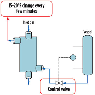 |
| FIG. 14. Flow diagram for system with unstable reboiler flow. |
This example demonstrates that repairs cannot be expected to be a successful long-term solution if the underlying cause of stress is not addressed. The large cyclic swings in outlet temperature were a clear indication of a process issue that should have been addressed, especially at the time of heat exchanger repair. Control valves must be sized properly for the operating conditions.
 |
|
FIG. 15. Flow diagram for reboiler showing location of control valve and outlet gas temperature measurement. |
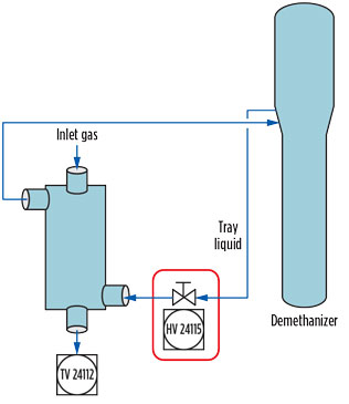
Thermal shock. Another consequence of not following guidelines is possible thermal shock. An improper control scheme was used for the control valve (HV24115) shown in the flow diagram in Fig. 16, which led to rapid opening and closing of the valve and resulted in rapid temperature changes of the reboiler. The temperature change of the reboiler gas outlet (TV24112) was more than 100°F (56°C)/min, and more than 180°F (100°C) over 4 min, and caused a leak by sheet separation from the bar column from the thermal shock. The response of the control valve after the initial opening led to a few other rapid temperature changes, as well. The temperature response is shown by the blue line in Fig. 16. The control valve % opening (on a different, smaller scale) is shown by the green line. The location of the resulting leak was near the reboiler liquid inlet header.
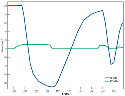 |
| FIG. 16. Reboiler gas outlet temperature rate of change with control valve opening. |
The observed temperature rate of change was > 25 times the recommended guideline of 3.6°F (2°C)/min. This example emphasizes the need to adjust process flowrates slowly so that operating guidelines for the temperature rates of change can be adhered to, thereby preventing thermal-stress-related issues.
Repair. Many types of leaks can be repaired. If a leak is detected, the BAHX vendor should be contacted for repair recommendations. All ASME repairs must be certified and in accordance with codes and local requirements. Some external leaks can be welded directly.
Cross-pass leaks (leaks between streams within the exchanger) can sometimes be “repaired” by removing the layers that are leaking from service by blocking them. A pitch of layers is defined as the group of layers that are repeated to make up the heat exchanger stack. Layers are typically blocked in pitches to maintain the design temperature profiles in the heat exchanger. The heat exchanger design with a proposed repair should be rated by the vendor to verify the post-repair unit performance.
Repairs cannot be expected to be a successful long-term solution if the underlying cause of a leak is not addressed; operating data should be evaluated, and the operating process or procedures should be revised to address the cause of stress. A replacement unit can be ordered at the time of repair to minimize future plant downtime, since BAHXs are custom-built items with long lead times.
Recommendations. BAHX reboilers provide a valuable service in natural gas and ethylene production. With proper attention to reboiler system design and operation guidelines, plant owners and operators can expect many years of trouble-free reboiler operation with plant robustness to handle a range of operating conditions.
For reboiler design, evaluate flowrates, piping flow regimes and system stability for all expected operating cases, including turndown conditions. To improve plant robustness, record and review plant operating data and use it to improve procedures to operate within the recommended guidelines. GP
Notes
aChart Industries Inc.’s Core-in-Kettle reboiler
bChart Industries Inc.’s SmartLayer technology
Literature cited
- Chart Energy & Chemicals Inc., “Installation, operation, and maintenance manual for Chart brazed aluminum heat exchangers (BAHX) and Core-in-Kettle assemblies,” October 2017.
- Aluminium Plate-Fin Heat Exchanger Manufacturer’s Association (ALPEMA), “The Standards of the Brazed Aluminum Plate-Fin Heat Exchanger Manufacturers’ Association,” 3rd Ed., 2010.
- GPA Midstream, “GPA technical bulletin brazed aluminum heat exchangers,” 2015.
- Nayyar, M. L., Piping Handbook, 7th Ed., B.446: McGraw-Hill, New York City, New York, 2000.
- Green, D. W. and R. H. Perry, Perry’s Chemical Engineers’ Handbook, 6th Ed., McGraw-Hill, New York City, New York, 1984.
- Gas Processors Suppliers Association, GPSA Engineering Databook, 13th Ed., 2012.
- Owen, D., “An experimental and theoretical analysis of equilibrium annular flows,” PhD thesis, University of Birmingham, 1986.
- Heat Transfer and Fluid Flow Service, “TM16: Stability assessment of boiling two-phase systems,” HTFS Handbook, August 1983.
- AspenTech, “TM12: Transition from intermittent to upward annular two-phase flow in a vertical tube,” HTFS Handbook, 1982.
- Heat Transfer Research Inc., “Report BT-1,” Fig. 5-5, 1980.
 |
Steven Vallee has worked as a Product Development Engineer at Chart Energy & Chemicals Inc. in LaCrosse, Wisconsin for 8 yr. His research activities include transient thermal analysis of BAHX and two-phase distributor designs. Dr. Vallee obtained a PhD in chemical engineering from the University of Massachusetts at Amherst and a BS degree from Worcester Polytechnic Institute in Worcester, Massachusetts.
Douglas Decker is the Product Development and Technology Manager at Chart Energy & Chemicals Inc. He has worked on all phases of BAHX product development since 1984. He holds a BS degree in mechanical engineering from South Dakota State University at Brookings.
Adam McNeilly is a Senior Product Development Engineer at Chart Energy & Chemicals Inc. His work is focused on transient thermal simulations and fatigue analysis of BAHX. He is a licensed PE and received his MS degree in mechanical engineering from the University of Wisconsin at Madison.


Comments