
Upgrade a gas plant to produce LPG by DWC and conventional methods—Part 1
M. M. Mostafa, N. A. EL-Emam, M. A. EL-Shafie and T. M. Aboul-Fotouh, Mining and Petroleum Engineering Department, Al-Azhar University, Cairo, Egypt
The LPG market has seen a steady increase in prices due to increasing demand for LPG worldwide, particularly for the petrochemicals, automotive, metal, ceramic and glass industries. While it is possible to recover LPG in natural gas processing operations, this raises the capital and operating costs of the plant considerably. For this reason, it is important to reduce costs during these processes.
The divided wall column (DWC), or fully thermally coupled distillation system (FTCDS), is one of the most promising technologies to minimize energy consumption and reduce operating costs. This technique of separation provides large potential energy savings compared to the conventional column method.
This article studies the addition of an LPG recovery plant to an existing gas plant by selecting the best of two alternative methods—the conventional approach, or a DWC “Petlyuk column.” The technical study is followed by an economic study for both methods using a proprietary simulation program.a
The results indicate that using a DWC will save more than 18% of power consumption required as compared to a conventional method, thereby reducing operating costs. Moreover, using the DWC will save more than 20% of the capital costs as compared to a conventional method. Furthermore, an economic analyzer shows that the respective payback periods for the conventional method and the DWC will be approximately 2.23 yr and 1.54 yr. The authors recommend the DWC method over the conventional method to achieve energy savings in gas plants.
Introduction. Natural gas contains heavier hydrocarbon components collectively known as NGL. These components include ethane, propane, butane, pentane and fractions of heavier hydrocarbons,1,2,3 and they must be removed to control the natural gas dewpoint NGL. They can also be sold as products or as feed for different industries.4,5,6
Separated NGL is sent to the LPG recovery plant to separate LPG, which contains propane (C3), isobutane (i-C4) and normal butane (n-C4) from stabilized condensate (C5+).6,7,8
LPG and condensate both have higher economic value than natural gas.5,6 Unfortunately, natural gas processes to recover LPG increase the initial and operating costs of the plant by requiring more power.3 For this reason, it is very important to optimize power consumption.9,10,11
The divided wall column (DWC) is one of the most promising technologies to minimize energy consumption and operating cost.10,12 Many techniques have been developed to recover LPG from NGL; some of these studies have focused on finding the most economic and optimized technology.13,14 In this study, a comparison between conventional LPG recovery methods and the DWC method is performed to discern the best method.
 |
|
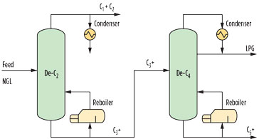
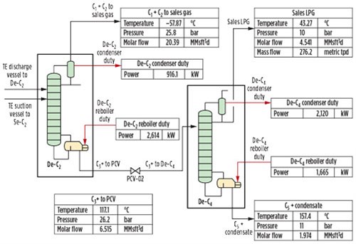
FIG. 1. Products from the deethanizer and debutanizer columns. |
The conventional method consists of two columns—the deethanizer (De-C2) and the debutanizer (De-C4)—arranged in series and operated at different pressure and temperature.1,12 The top products from the deethanizer column are methane and ethane in the vapor phase, while the bottom products are propane and heavier (C3+) in the liquid phase.1 For the debutanizer column, the top products are LPG (C3 and C4) in the liquid phase, and the bottom products are pentane and heavier (C5+) in the liquid phase, as shown in Fig. 1.
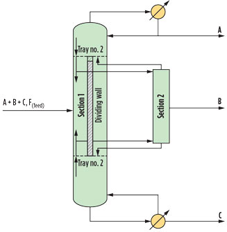
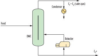
Conventional arrangement. DWC is a method to save power consumption during distillation by using one column to produce more than two products.9,12,14 The DWC tower has a wall that divides the tower into several sections (Fig. 2). The DWC acts as three connected columns to produce three products (Fig. 3).12,15,16
 |
|
FIG. 2. Sections of a DWC. |
The DWC can save capital costs by using one tower instead of two towers, and one reboiler and one condenser instead of two reboilers and two condensers. It can also reduce operating costs by decreasing the duty of the reboiler and condenser and decreasing maintenance costs for all equipment.13,15,17,18
 |
|
FIG. 3. Process schematic for a DWC. |
In this study, the LPG recovery plant was designed and simulated using a proprietary simulation program,a followed by an economic study using the program’s economic analyzer to investigate the best method to recover the LPG from natural gas.16
Methodology: Existing plant configuration. Natural gas must be purified before it enters the low-temperature facility. The purpose of gas purification is to separate condensate (C5+), noncondensable acid gases and water from the natural gas to make these fluids suitable for sale or disposal.1,3,6
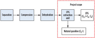
The existing plant consists of separation, compression and dehydration sections (Fig. 4). The dehydrated gas is sent to a sales metering station and then to the national electricity grid. The aim of this study was to raise the value of the gas product by adding an LPG recovery unit, using a low-temperature technique, and then to recover LPG from the NGL through both conventional and DWC methods.
 |
|
FIG. 4. Process scheme for the existing plant configuration. |
The natural gas coming from offshore is received in slug catchers to remove liquids, and then sent to a high-pressure separator to remove the remaining droplets of liquids in the gas before pressurization by two compressors. First, a main compressor pressurizes the gas from 17 bar to 50 bar, and then a booster compressor pressurizes the gas from 50 bar to 83 bar. The 83-bar gas is directed to the dehydration unit’s temperature swing adsorption (TSA) section to control hydrocarbon dewpoint before the gas is routed to a metering station. The LPG recovery plant is added after the dehydration unit, after removing all condensate and water from the gas (see red box in Fig. 4).
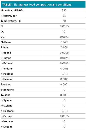 |
Proposed NGL recovery. Many technologies are available to recover NGL from natural gas. In this study, a turboexpander and a cold box are used together to separate NGL from natural gas.4,6,19 The composition of natural gas exiting the dehydration unit to be used as feed for the LPG recovery plant is shown in Table 1. The natural gas feed stream is cooled to allow the heavier hydrocarbons to be condensed and separated.1,4,6 The cooling process is achieved with a cold box and a turboexpander.4,6,20
 |
|
FIG. 5. NGL recovery process. |
Fig. 5 illustrates the low-temperature process for natural gas to recover NGL. The feed gas is cooled from 30°C to 10°C via a cooler, where the heat exchange between the inlet feed and the sales gas comes from the cold box, and the overhead vapor comes from the distillation tower (D-C2) in the case of a conventional system, or from a DWC in a DWC distillation system. The gas is then directed to a pressure control valve (PCV-01), which reduces the pressure of the gas stream from 82.8 bar to 52.8 bar, thereby reducing the temperature of the gas stream from 10°C to –4.095°C.
The liquid starts to appear in the stream after the control valve, which directs to a cold box to cool the stream from –4.095°C to –60°C, with a reduction in pressure to approximately 2 bar across the cold box. The other two streams in the cold box are defined after simulation of the turboexpander package.
The cold gas exits the cold box and is directed to the turboexpander unit, which consists of a turboexpander suction vessel to separate the liquid condensed in the stream before entering the turboexpander, a turboexpander to reduce the pressure of the stream, and a turboexpander discharge vessel to separate the vapor and liquids.4 The vapor exiting from the turboexpander suction vessel enters the turboexpander, while the liquid is directed to a cold box to exchange thermally with the feed. The turboexpander reduces the pressure of the stream from 50.8 bar to 35.8 bar, and the temperature is subsequently reduced from –60°C to –76.95°C. Afterward, the stream exits the turboexpander via the turboexpander discharge vessel.
The separated gas from the turboexpander discharge vessel is directed to the cold box to exchange thermally with two other streams, and then sent to the sales gas compressor. The liquid exiting from the bottom of the turboexpander discharge vessel is directed to the distillation tower via the subcooler, where the heat exchange occurs between the compressed sales gas as a hot stream and the cold stream coming from the turboexpander discharge vessel.
To save power, two heat exchangers were used. The first exchanger was used to exchange the heat between the inlet feed going to the process control valve as a hot stream, and the two sales gas streams coming from the cold box and the distillation tower as a single cold stream. The second exchanger was used to exchange the heat between the liquid exiting from the turboexpander discharge vessel as a cold stream, and the sales gas coming from the sales gas compressor as a hot stream.
After NGL is recovered from the natural gas, there are two streams containing NGL. The first stream comes from the bottom of the turboexpander discharge vessel via the second heat exchanger, and the other stream comes from the bottom of the turboexpander suction vessel via the cold box to the distillation column. These two streams have an NGL composition that allows for the inclusion of a distillation column to produce LPG.6
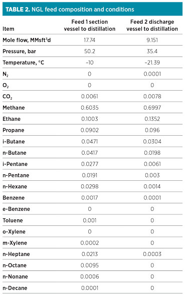
LPG recovery process. This section simulates the distillation system of NGL to produce LPG by two methods—the conventional method and the DWC method, or Petlyuk column. The compositions of the two streams of recovered NGL that are used as feed for the LPG recovery plant are shown in Table 2 with pressure, temperature and flowrates. A simulation programa is used to design and simulate the LPG recovery plant for both methods.12,16
 |
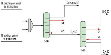
Conventional method simulation. A short-cut calculation method is used to define the initial estimates for the number of trays for each tower.12,16,18 The two streams coming from the turboexpander suction vessel and turboexpander discharge vessel are theoretically mixed to allow connection to the short-cut calculation column (Fig. 6).
 |
|
FIG. 6. Short-cut calculations for the conventional method. |
The conventional method consists of two columns, a deethanizer (De-C2) and a debutanizer (De-C4). The short-cut calculation must also consist of two columns (T-10 and T-20) to represent the two series columns in the conventional-method deethanizer and debutanizer (De-C2 and De-C4), respectively.
A simulation of the short-cut calculation method depends on the light key in bottoms and the heavy key in distillates. For column T-10, the light key in the bottoms is ethane (C2) with 0.005 mole fraction, and the heavy key in distillate is propane (C3) with 0.005 mole fraction. In column T-20, the light key in the bottoms is n-butane (n-C4) with 0.0004 mole fraction, and the heavy key in the distillate is i-pentane (i-C5) with 0.021 mole fraction.
The results obtained from the short-cut calculation are defined in Table 3. They are taken as input data in a rigorous simulation for two conventional towers. Results from Table 3 are used as input data for rigorous simulation.12
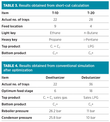 |
Fig. 7 illustrates the converged simulation for the conventional deethanizer and debutanizer. The feed for the conventional columns includes two streams coming from the turboexpander suction vessel and the turboexpander discharge vessel.
 |
|
FIG. 7. Conventional simulation method. |
All data in Table 4 are derived from simulating the conventional columns and then optimizing both columns. For the deethanizer (De-C2), optimization is done by replacing the feed trays for both feed streams. For the debutanizer (De-C4), optimization is done by replacing the feed tray for stream C3+, which enters the column as feed.12,21 Optimization is necessary to maintain the optimum operating condition with lower heat duty for both the reboiler and the condenser.12,21
DWC method simulation. No identified method exists in the proprietary simulation programa to simulate the DWC, so the simulation of the DWC depends on two columns—the pre-fractionator and the main column.12,18,22
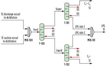
As in conventional simulation, the short-cut calculation method is performed to obtain initial estimates for the tower, such as the numbers of trays and feed trays. The three short-cut columns (Fig. 8) are equivalent to the DWC (Fig. 3).12,18
 |
|
FIG. 8. Short-cut calculation methods for DWC. |
Column T-100 is equivalent to the prefractionator tower, while the other two columns are collectively equivalent to the main column. For column T-100, the light key in the bottoms is ethane (C2) with 0.0001 mole fraction, while the heavy key in the distillate is propane (C3) with 0.001 mole fraction. The top product is a vapor stream that enters column T-101 as a feed.
The liquid stream exiting from the bottoms enters column T-102 as a feed. For column T-101, the light key in the bottoms is ethane (C2) with 0.08 mole fraction, and the heavy key in the distillate is propane (C3) with 0.0001 mole fraction. The top product is sales gas (C1 + C2), while the bottom product is LPG. For the last column (T-102), the light key in the bottoms is n-butane (n-C4) with 0.01 mole fraction, while the heavy key in the distillate is i-pentane (i-C5) with 0.01 mole fraction.
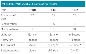 |
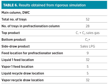
Table 5 contains the data obtained from the short-cut calculation to simulate the DWC. These data are used as raw data for the rigorous simulation of the DWC. Depending on the data obtained from the short-cut calculation method, the number of trays for the prefractionation column is 22, while the number of trays in the main column is equal to the number of trays in column T-101 plus the number of trays in column T-102 plus two trays for a condenser and a reboiler—i.e., the total number of trays in the main column = 25 + 25 + 2 = 52 trays. Fig. 9 illustrates the rigorous simulation for the DWC.
 |
|
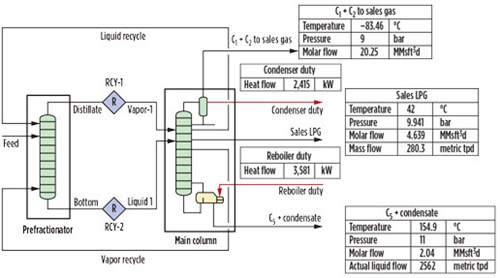
FIG. 9. DWC simulation. |
Since no identified method exists to simulate the DWC in the proprietary simulation programa or any other programs, the absorber column (T-100) is used to represent the prefractionation column. This column is connected to the main column, as shown in Fig. 9. To converge the DWC in the proprietary simulation program involves five degrees of freedom, which means that at least five input parameters must be interred to the simulation to converge the column.12 The streams connected to the main column include the following:12,16
- The feed stream connected to the prefractionation column is the feed exiting from the low-temperature plant
- Stream Vapor-1 is the vapor phase stream exiting from the top of the prefractionator column (distillate) and acts as the first feed for the main column
- Stream Liquid-1 is the liquid phase stream exiting from the bottom of the prefractionation column (bottom) and enters the main column as a second feed
- Stream C1 + C2 sales gas is the overhead product from the DWC and contains mainly methane and ethane
- Stream Sales LPG is the side product from the DWC
- Stream C5+ Condensate is the bottom product of the DWC and mainly contains pentane and heavier hydrocarbons
- Stream Liquid Recycle represents the liquid exit from
- the main column and enters the prefractionation column in the liquid phase
- Stream Vapor Recycle represents the vapor stream, which leaves the main column and enters the prefractionation column in the vapor phase
- The feed tray of stream Vapor-1 must be the same tray for stream Liquid Recycle, and the feed tray for stream Liquid-1 must be the recycle tray for stream Vapor Recycle; therefore, the number of trays between the two feed streams, Vapor 1 and Liquid 1, is equal to the number of trays in the first section (prefractionation column).12, 13
Table 6 contains the results obtained from the rigorous simulation for the DWC after optimization.
 |
Part 2 of this article, to appear in the January/February 2019 issue, will discuss the results of the study to produce LPG by use of a DWC and a conventional method. GP
Literature cited
- Campbell, J. M., L. Lilly and R. Maddox, “Gas conditioning and processing,” Vol. 3, Iss. 2, PennWell Conferences and Exhibitions, Houston, Texas, November 1999.
- Park, J. H., M. S. Khan, R. Andika, M. Getu, A. Bahadori and M. Lee, “Techno-economic evaluation of a novel NGL recovery scheme with nine patented schemes for offshore applications,” Journal of Natural Gas Science and Engineering, Vol. 27, 2015.
- Wang, X. and M. Economides, Advanced Natural Gas Engineering, Elsevier, 2013.
- Younger, A. H. and P. Eng, “Natural gas processing principles and technology—Part 1,” Gas Processors Association, Tulsa, Oklahoma, 2001.
- Shelley, C., “The story of LPG,” Poten & Partners, 2003.
- Mokhatab, S. and W. A. Poe, Handbook of Natural Gas Transmission and Processing, Gulf Professional Publishing, 2012.
- Raheem, A. B., A. Hassan, S. A. Samsudin, Z. Z. Noor and A. Adebobajo, “Comparative economic investigation options for liquefied petroleum gas production from natural gas liquids,” American Journal of Chemical Engineering, Vol. 3, Iss. 2–1, 2015.
- “Engineering Data Book,” Gas Processors Suppliers Association, Vol. 2, 2004.
- Navarro‐Amorós, M. A., R. Ruiz‐Femenia and J. A. Caballero, “A new technique for recovering energy in thermally coupled distillation using vapor recompression cycles,” AIChE Journal, Vol. 59, Iss. 10, 2013.
- Gómez‐Castro, F. I., J. G. Segovia‐Hernández, S. Hernandez, C. Gutiérrez‐Antonio and A. Briones‐Ramírez, “Dividing wall distillation columns: Optimization and control properties,” Chemical Engineering & Technology, Vol. 31, Iss. 9, 2008.
- Ching, T. C., J. Nandong and M. Getu, “Retrofitting options for natural gas liquid (NGL) fractionation trains using the concept of single column development,” Procedia Engineering, Vol. 148, 2016.
- Kumar, R. P., “Retrofitting industrial, conventional column systems to Petlyuk/divided wall columns,” Doctoral dissertation, 2008.
- Khabibullin, E., F. Febrianti, J. Sheng, S. Bandyopadhyay and S. Skogestad, “TKP4170 process design project,” 2010.
- Long, N. V. D., L. Q. Minh, F. Ahmad, P. Luis and M. Lee, “Intensified distillation‐based separation processes: Recent developments and perspectives,” Chemical Engineering & Technology, Vol. 39, Iss. 12, 2016.
- Nguyen, T. D., “Conceptual design, simulation and experimental validation of divided wall column: Application for non-reactive and reactive mixture,” Doctoral dissertation, 2015.
- Halvorsen, I. J., I. Dejanović, S. Skogestad and Ž. Olujić, “Internal configurations for a multi-product dividing wall column,” Chemical Engineering Research and Design, Vol. 91, Iss. 10, 2013.
- Le, Q. K., “Design and simulation of dividing wall column for ternary heterogeneous distillation,” Master’s thesis, Norwegian University of Science and Technology, 2014.
- Rangaiah, G. P., E. L. Ooi and R. Premkumar, “A simplified procedure for quick design of dividing wall columns for industrial applications,” Chemical product and process modeling, Vol. 4, Iss. 1, 2009.
- Abdulrahman, R. K., M. H. Zangana and I. M. Sebastine, “Optimal NGL recovery from natural gas using turboexpander: A case study and simulation,” Chemistry and Technology of Fuels and Oils, Vol. 51, Iss. 5, 2015.
- Abdulrahman, R. K., M. H. Zangana and I. M. Sebastine, “Optimal NGL recovery from natural gas using turboexpander: A case study and simulation,” Chemistry and Technology of Fuels and Oils, Vol. 51, Iss. 5, 2015.
- Kiss, A. A., Advanced Distillation Technologies: Design, Control and Applications, John Wiley & Sons, Hoboken, New Jersey, 2015.
- Mustafa, M. and J. A. Wilson, “An approach towards the design of a Petlyuk column using HYSYS,” Sudan Engineering Society Journal, Vol. 58, No. 1, March 2012.
Note
aAspen HYSYS
 |
MOHAMED MOHAMED MOSTAFA is an Operational and Gas Processing Engineer at Rashid Petroleum Co. in Egypt. He is responsible for operating gas and oil plants, including shutdown and startup, design and maintenance of mechanical isolation/de-isolation, storage and loading of condensate, etc. He also oversees the management and operation of subsea wells, and served as Commissioning and Startup Engineer for an extension of the Torus Libra project. He holds a BSc degree in petroleum engineering from Al-Azhar University.
 |
NOUR AHMED EL-EMAM is a Professor of Petroleum Engineering in the Mining and Petroleum Engineering Department at Al-Azhar University in Cairo, Egypt. He has published more than 60 papers in petroleum engineering publications and at international conferences. Furthermore, he has supervised more than 20 PhD and MSc candidates in petroleum engineering. Dr. El-Emam holds a PhD in petroleum engineering from the Technical University of Heavy Industries in Hungary.
 |
MASOUD A. EL-SHAFIE is an Emeritus Associate Professor of Petroleum Engineering in the Mining and Petroleum Engineering Department at Al-Azhar University. He specializes in petroleum refining engineering, petrochemical technology and natural gas processing. In addition, he has published many articles in petroleum refining and engineering and gas processing technology publications.
 |
TAREK M. ABOUL-FOTOUH is an Associate Professor of Petroleum Engineering in the Mining and Petroleum Engineering Department at Al-Azhar University. He is also an Associate Professor in the Chemical Engineering Department at the British University in Egypt, and an Associate Professor in the Petroleum Engineering Department at the Future University in Egypt. Dr. Aboul-Fotouh has published more than 30 articles on petroleum refining engineering and fuel technology. Furthermore, he was the Chairman of the Second International Conference and Expo on Oil and Gas in Rome, Italy, in October 2016. He is also a member of the Society of Petroleum Engineers (SPE) and the American Institute of Chemical Engineers (AIChE). Dr. Aboul-Fotouh holds a PhD in chemical engineering from Azerbaijan State Oil Academy in Baku, Azerbaijan.


Comments