
Select NGL recovery and optimization technologies using simulation and algorithm
S. J. Lee, H. Y. Yoon and G. S. Chang, GS Engineering and Construction, Seoul, South Korea
It can be difficult to find common criteria for the design of NGL recovery plants. Many processes are available in the market for NGL recovery. These processes typically utilize cryogenic-turboexpander-based processes with one or more reflux streams, such as conventional industrial single-stage (ISS), gas subcooled process (GSP), cold residue reflux (CRR), recycle split vapor (RSV) and others.1
The differences from one scheme to the next include the source of the reflux stream(s) and slight variances in heat integration. They show different system configurations and different operating conditions due to the intrinsic complexity caused by the many design variables interacting with each other. Technology selection and optimization of the NGL recovery unit are not straightforward for the process engineer.
To optimize the NGL recovery process configuration and design conditions, it is essential to appropriately outline parameters with significant effects on performance during the design process. The objective is to develop a standard procedure to select a suitable NGL recovery process to meet the required C2/C3 recovery levels. Various design parameters are considered, such as operating pressure, composition (richness and impurities, such as CO2 content), split ratio, expansion ratio, operating flexibility (ethane rejection/recovery), etc.
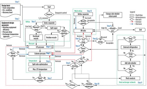 |
| FIG. 1. Technology selection and optimization algorithm. |
This article describes a systematic approach to NGL recovery technology selection and optimization based on process simulations. It also shows the implementation of an algorithm to optimize the design variables of the NGL recovery process (Fig. 1). The algorithm diagram includes several essential elements:
- Guideline to adopt a single-column or two-column system for cost-effectiveness
- Logic diagram to find the optimized operating pressure of the column with split-vapor ratio optimization
- Check point of operating condition to avoid unstable operation
- Comparison point between single-reflux system and multi-reflux system regarding operating pressure
- Loop to minimize refrigeration duty and investment cost by using pinch technology.
The algorithm may be used by four types of personnel:
- A process engineer who will select and design the process technology for the basic engineering stage
- The owner of a new plant who will select the optimum process technology
- The bidder of a new project who must verify the selected process
- An operator who wishes to avoid a problematic situation caused by an unstable operating condition.
Technology selection and optimization algorithm. Technology selection begins with the simplest and cheapest process that includes the common basic items of a low-temperature separator (LTS) and a main column (DeC1). Proceeding step by step, as shown in Fig. 1, auxiliary items are added to meet the required recovery demands, thereby becoming a more complex system. This algorithm helps identify which obstacles must be overcome and which evaluations must be completed prior to the construction of a cost-effective plant for specific project objectives.
Step 1: Confirm design basis. The design basis is the stepping stone for the selection of the NGL recovery process. It starts with basic parameters, such as feed composition, battery limit condition and target recovery level. These parameters affect mainly cost and process efficiency. These values must be confirmed before a technology selection algorithm is started.
Natural gas feedstock comes from one or more gas wells. Depending on the production year and the operation of upstream units (e.g., long pipe, treating unit and dehydration unit), gas pressure and composition may be varied, so the tabulation of feed conditions is important for selecting the best process configuration.
Step 2: Determine mechanical design parameters. Such parameters include mechanical characteristics, such as rotating equipment efficiency, the pressure drop of each piece of equipment, minimum heat exchanger temperature approach, etc. Some values (e.g., pressure drop) may need to be adjusted up or down for higher or lower operating pressures. Rotating equipment efficiencies generally increase with plant size.
These parameters must be determined carefully, because they affect the entire performance of the process and the selection result. The exact values of these parameters usually come from the vendor’s information. In the conceptual design stage, typical values are to be used.2
Step 3: Make reflux configuration changes. The reflux configuration varies with the project requirement. If the project purpose is dewpoint control only, then no additional items (such as turboexpander or external reflux streams) are required.
For C2/C3 recovery, the turboexpander-based process is to be used. In case of low recovery level, the turboexpander process utilizes a non-refluxed column. This design provides no external reflux feed and no fractionation stages above the expander feed nozzle on the column. This has often been referred to as the ISS process.
High-level C2 recovery processes typically utilize a single column with one or more reflux streams. The column is externally refluxed with a subcooled and flashed process stream (split-vapor process). It also has fractionation stages above the expander feed. This eliminates dependence on the expander to generate column reflux, and it provides better recovery at lower energy consumption. When the project requires ethane-rejection mode, flexibility to expander plants for high propane recovery should be evaluated, regardless of the ethane recovery, by providing multiple external reflux streams for the column (residue recycle process).
High-level C3 recovery processes typically utilize a two-column process where the first column is generally refluxed with a stream generated from the second column (overhead recycle process). The first column will make a rough component separation, while the second column will produce an on-spec liquid product. This energy-efficient process is capable of recovering essentially all the contained propane.
 |
|
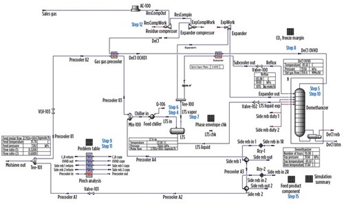
FIG. 2. Simulation template for split-vapor (GSP) process. |
Many different types of process schemes are available. The differences from one scheme to the next include the source of the reflux stream(s) and slight variances in heat integration. This step is a guideline to provide the process engineer with a reference before selecting an optimized process scheme. Through this algorithm, the effect of the variances in configuration can be evaluated. In this article, the split-vapor process (GSP), as shown in Fig. 2, is used as the reference case to show how this algorithm finds optimum condition at 80% ethane recovery.
Step 4: Set LTS operating pressure. Since no economical cold utility is available for overhead condensing in a natural gas field where infrastructure is not well prepared, the cold energy generated by the pressure drop between the LTS and the column is used to recover NGL product; this is why it is called self-refrigeration.
The initial LTS pressure is set by feed pressure after adjustment for pressure drop. It can also be changed to allow proper operation and recovery: it can be increased by feed gas compression or decreased by pressure let-down for effective and stable operation. Most importantly, this pressure should be sufficiently high to generate the cold temperatures required for efficient NGL recovery.
Step 5: Set column operating pressure. The main column overhead conditions should be determined according to required product specification and recovery level. The design objective is to achieve the required recoveries with minimal capital and operating expenses. For a cryogenic turboexpander-based process, the design objective is achieved primarily by minimizing residue gas compression, which is the costliest option in terms of both CAPEX and OPEX. In pursuit of this goal, the column pressure should be operated at the highest possible pressure while still meeting recovery objectives.
In general, there are upper and lower limits to column pressure. The upper limit is a constraint of the column, which must operate at pressures low enough to prevent the loss of separation efficiency and to maintain phase stability (i.e., avoid critical conditions). The lower limit is CO2 freezing temperature.
The operating pressure is adjusted by examining the compression ratio, the column design pressure and CO2 freezing temperature. These parameters are highly correlated with costs and operational stability. A cost trade-off exists between the number of compressor stages and the column design pressure. As a starting point, two compressor stages with a compression ratio of approximately 2 stage can be used.
Typical column pressure varies in the range of 25 barg–32 barg. For a preliminary design, 25 barg can be used as an initial point. Through following these iteration steps, the optimum pressure can be found.
Step 6: Optimize split-vapor ratio and LTS temperature. When the reflux configuration and the operating pressure of LTS and column DeC1 are set, the LTS temperature is determined at a fixed recovery level. This can be easily accomplished by using an adjustment utility in the simulation program. The split-vapor process uses a small portion of the split vapor from the LTS as the top reflux to the DeC1 after condensation and substantial subcooling. When the split vapor is used to provide subcooled reflux, the split ratio should be optimized since it affects the LTS temperature and recovery level.
The point is that the highest LTS temperature is advantageous to heat exchanger network design at the same recovery level and the same operating pressure. The LTS temperature increases when the heat recovery in the subcooler increases. To maximize the LTS temperature, heat recovery in the subcooler should be maximized by adjusting the split ratio.
A case study was conducted to evaluate the effect of split ratio and the LTS operating temperature at the same operating pressure to achieve 80% ethane recovery. The split-vapor ratio was 0.15 for Case 1 and 0.33 for Case 2.
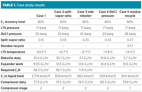 |
As per the simulation results, Case 1 requires 37.5% more reboiler duty and 41.8% more refrigeration duty than Case 2, as shown in Table 1. The lower temperature of the LTS separator tends to over-condense methane (C1) in the liquid phase. Column DeC1 is designed to remove methane in NGL product (C1/C2 ratio is 0.017). When the over-condensed C1 is fed to the DeC1, it requires more reboiler duty to strip C1. It also needs corresponding cold energy to provide enough reflux to meet the required ethane recovery level.
 |
|
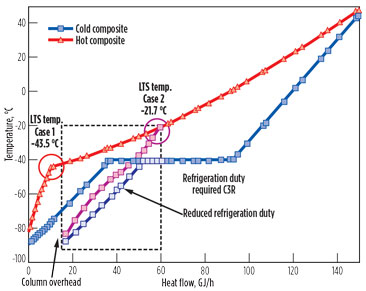
FIG. 3. Composite curve for Case 1 (split-vapor ratio of 0.15) and Case 2 (split-vapor ratio of 0.3). |
Fig. 3 shows the T-H diagram for the composite curve of Case 1 and Case 2 (reboiler duty excluded). Since the high-quality cold energy source (low temperature) is limited to the DeC1 overhead stream, it is important to recover heat in the subcooler as much as possible. For this, the split ratio should be optimized. In the T-H diagram, the degree of slope is equal to the heat capacity. When the amount of split vapor to the subcooler increases, the hot-side curve leans toward the horizontal axis. By adjusting the split ratio, the hot and cold composite curves can move closer to each other. This will increase heat recovery in the subcooler and generate more reflux to the DeC1 column. Finally, the highest temperature of the LTS can be achieved by optimizing the split-vapor ratio at a given recovery level. This hot temperature prevents over-condensing of methane, so it can reduce the total amount of cold energy (external refrigeration duty).
Step 7: Check vapor-liquid equilibrium stability. After the operating condition of LTS is set, the stability should be checked. The LTS works as both an expander suction knockout drum and as a supplier of reflux to the main column. As a result, the liquid disengagement must be considered in addition to the operating condition for NGL recovery and efficiency.
Many first-generation expander plants experience instability problems associated with vapor-liquid equilibrium. When the operating pressure is above a critical point, retrograde vaporization will occur as temperature decreases. Small changes in the separator temperature cause large changes in the amount of vapor entering the expander, resulting in sudden changes in the expander speed that cause the tower pressure to surge and the process gas temperatures to fluctuate, until the entire plant is oscillating.3 This can be tested by examining the vapor flowrate variation at the time of temperature change, as shown in Table 2. When the temperature drops below –48°C, vapor flowrate begins to increase, eventually reaching 0 at –54°C.
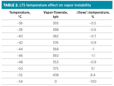 |
This region of instability can be avoided by keeping the separator temperature warmer than the optimum temperature, which is achieved in Step 6. However, this will sacrifice ethane recovery. The next step to avoid vapor instability without limiting product recovery is to decrease the DeC1 pressure. If the LTS pressure is higher than the critical pressure, then the LTS pressure should be decreased below the critical pressure.
Step 8: Check CO2 freeze margin. CO2 freezing must be prevented since it affects plant operation and process efficiency. It is checked using the CO2 freezing temperature approach (∆TCO2) at some locations.4 Based on the selected operating pressure, the CO2 freezing temperature of the stage liquids and vapors in the column should be checked. The expander outlet stream should also be checked. When the CO2 freezing temperature approach is less than the required margin (or 3°C), the column operating pressure from Step 5 should be increased to raise the column operating temperature. This routine should be repeated until the CO2 freezing temperature margin is sufficient.
 |
|
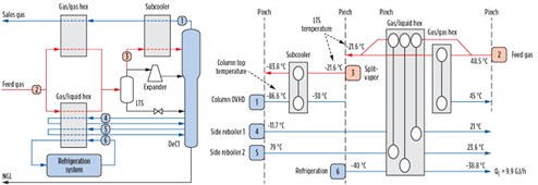
FIG. 4. Conceptual diagram for pinch analysis. |
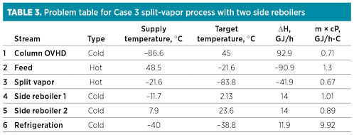
Step 9: Perform pinch analysis. The next step is to check the feasibility of the operating condition defined by previous steps in terms of heat balance. For this purpose, pinch technology is utilized. The temperature, duty, flow and heat capacity from the stream data in the simulation should first be tabulated, as shown in Fig. 4. The data are summarized in Table 3.
 |
In the precooler, the feed gas is cooled to the LTS temperature determined in previous steps for the desired recovery level. It consists of a gas/gas exchanger and a gas/liquid exchanger. Since the lowest cold utility (if required) is a propane refrigerant of –40°C for economic reasons, the remaining cold energy below –40°C will be provided by the process gas itself. Potential cold energy sources are the column overhead, side reboiler draw, main reboiler draw and column bottoms.
The authors recommend starting with the column overhead as the only available cold source; no external refrigeration system is installed. In this step, the capital cost is evaluated; refrigeration system installation is not considered. If it is not found to be feasible, the cost will be added. If temperature cross emerges, one or more side reboilers should be added, if possible. If a side reboiler cannot provide enough cold energy, an external refrigeration system should be added.
 |
|
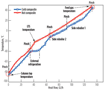
FIG. 5. Composite curve for Case 3 split-vapor process with two side reboilers. |
This process can be plotted as shown in Fig. 5. More side reboiler duty results in less external refrigeration duty. At the same recovery level, total reboiling duty will be almost constant; therefore, the portion of side reboiler duty will be limited because the side-draw temperature increases when the side reboiler duty increases. This portion will be optimized until “pinch”—i.e., the cold-side curve of the side reboiler close to the hot-side composite curve. As per simulation results (Case 3), the required refrigeration duty can be reduced by 70% compared to Case 2, when reboiling duty is used as side reboiler (Table 1).
Note that composite curves vary with operating condition. Phase change should be considered when making the composite curve. The energy target should include not only the refrigeration duty but also the compressor power, which is affected by pressure. When these provisions fail to work and result in temperature cross, the pressure difference between the feed and the column should be increased because the defined operating pressure is not feasible. This can be achieved by decreasing the operating pressure of the column or increasing the feed gas pressure through feed gas compression.
Step 10: Change operating pressure. To determine whether to increase LTS pressure or decrease column pressure when the operating pressure is not feasible, economical efficiency must be evaluated. If a feed gas compression system is already installed, then increasing LTS pressure may be more economical; however, if it exceeds the critical pressure, then the feed pressure cannot be increased due to the LTS phase envelope margin. The process efficiency begins to decrease over 48 barg due to the over-condensing of methane. For inlet gas pressures in the range of 51 barg–69 barg (750 psig–1,000 psig), the turboexpander pressure drop that is required to meet the recovery objectives results in a column operating pressure within the range of satisfactory operation. The result is an efficient, well-integrated process.
However, when the inlet gas pressure is above this range, reducing the column pressure will be more economical. Before changing the column operating pressure, the CO2 freezing temperature margin must be checked. Case 4 shows the effect of column pressure decrease on required refrigeration duty. When the pressure is decreased by 23 barg, the external refrigeration system can be removed. If column pressure cannot be decreased due to CO2 freezing, it is not possible to achieve the desired recovery with the present process configuration. In this case, it is advisable to proceed directly to Step 13.
Step 11: Check excess duty. If a sufficient gap exists between the hot and cold composite curve without temperature cross—meaning that there is excess duty—then column operating pressure can be increased until the excess duty reaches zero (pinch). Repeat this step to find the highest column pressure. To evaluate the economic benefit, two cases can be tested—one with a refrigeration system and one without. For example, the installation of an external refrigeration system will require a higher system cost, but it may also reduce the cost of the residue gas compression system because the column pressure can be increased.
Step 12: Check stages of residue gas compressor. From Step 1 to Step 11, this algorithm led to an optimized operating pressure with a simple reflux configuration. This process could be improved by introducing a multi-reflux system. A simple way to decide whether to introduce a multi-reflux system is to check the number of stages of the residue gas compressor. If the number of stages can be reduced by reflux modification, then adding a leaner reflux is more economical.
Case 5 shows that when the residue recycle is added to the top of the column as reflux, the column operating pressure can be increased by 28 barg at the same recovery level. In spite of less flow being expanded via the expander, this leaner reflux flow permits an improved ethane recovery even at a higher column pressure, thereby reducing the compression ratio. Since the pressure ratio is decreased, the discharge temperature is decreased to the point where a one-stage compressor can be adopted. It also provides an advantage in reducing the risk of CO2 freezing in the DeC1.
Step 13: Add leaner reflux. The maximum recovery achievable with split-vapor processes is limited to the ethane recovery by the vapor-liquid equilibrium in the top section of the column because the split vapor, which is used as reflux, contains a considerable amount of ethane. When the residue recycle is introduced as reflux, the column has an intrinsic rectifying section (RSV process). The ethane and heavier components in the column overhead can be recovered as needed by increasing the recycle ratio of the leaner reflux, which has the same composition with column distillate.
The design and turndown capacity of the residue gas compressor must be evaluated for operational stability. A dedicated recycle compressor may be installed separately with a residue gas sendout compressor.
When the recycle ratio is too high, an additional reflux drum can be installed. It will provide leaner split vapor so that the residue recycle rate can be reduced at the same recovery level. If the required recovery level is higher than 95%, then a multi-reflux system is more economical.
Step 14: Check off-design cases. In a gas processing plant, several designs may exist to accommodate different feeds and seasons. The designer should check for abnormal cases that enhance productivity and reliability within a range of flexibility. To evaluate these off-design cases, mechanical design parameters (rotating equipment efficiency, pressure drops and exchanger rates) specified in Step 2 should be adjusted for all plant simulations.
Step 15: Check product specifications. All required product specifications must be checked carefully. For example, if CO2 concentration in the NGL product exceeds the required product specification, then heat must be added to the column with the side and/or main reboiler to raise the temperature in the bottom of the stripping section. However, this may result in a loss of ethane recovery.
To reduce CO2 concentration without significant ethane recovery loss, carbon dioxide control (CDC) can be applied.5 In a typical reboiler or side reboiler, the entire column downflowing liquid stream is withdrawn from the tower and passed through a heat exchanger, then returned to the column at essentially the same point in the column. With the CDC scheme, a portion of the column downflowing liquid is withdrawn from a point higher up in the column. Since the relative volatilities for CO2 and ethane are very similar, methane vapor is a much more effective stripping agent than ethane vapor, which increases the stripping efficiency in the column. For the RSV process, the flexibility of the residue recycle ratio can be combined with the advantages of the CDC scheme to reduce the CO2 concentration of the bottom product with a smaller drop in ethane recovery.6
Recommendations. At the beginning of the NGL recovery project, process technology is selected without systematic evaluation, due to its intrinsic complexity. The process design chosen at this stage is usually not changed until the end of the project, which can result in an uneconomical design in terms of CAPEX and OPEX.
An algorithm to find the most economical technology and the optimized operating condition has been discussed. By following the steps outlined, a process engineer can obtain the most economical process configuration, as well as the optimized operating condition. Anticipated operational problems can also be checked.
This step-by-step process can be used to verify if the selected process technology is adequate at the basic engineering or EPC bidding stage. It can also be applied to an operating plant to test whether or not the existing design is optimum, or if improvements are needed for the next retrofit project.
The final process selection should be based on a detailed cost-benefit analysis that examines the costs of investment, depreciation and the market price of liquid ethane. GP
Literature cited
- Pitman, R. N., “Next generation processes for NGL/LPG recovery,” Gas Processors Association (GPA) Annual Convention, Austin, Texas, 2009.
- Lynch, J. T., “How to compare cryogenic process design alternatives for a new project,” GPA Annual Convention, San Antonio, Texas, 2007.
- Lynch, J. T., J. D. Wilkinson, H. M. Hudson and R. N. Pitman, “Process retrofits maximize the value of existing NGL and LPG recovery plants, Ortloff Engineers Ltd., Midland, Texas.
- Eggeman, T. and S. Chafin, “Pitfalls of CO2 freezing prediction,” GPA Annual Convention, San Antonio, Texas, 2003.
- Hudson, H. M., J. D. Wilkinson, J. T. Lynch and M. C. Pierce, “Reducing treating requirements for cryogenic NGL recovery plants,” GPA Annual Convention, San Antonio, Texas, 2001.
- Pennybaker, K. A., S. E. Wolverton, S. W. Chafin and T. R. Ruddy, “A comparative study of ethane recovery processes,” River City Engineering Inc., Lawrence, Kansas, 2000.
 |
SUKJOO LEE is a Process Engineer at GS Engineering and Construction. He has more than 8 yr of process modeling and design experience in petrochemicals and gas processing, with a focus on NGL recovery and sulfur recovery technologies. He holds a degree in chemical engineering from Hanyang University in Seoul, South Korea.
 |
HYUN-YONG YOON is a Process/Commissioning Engineer at GS Engineering and Construction. He has more than 7 yr of process modeling, design and commissioning experience in refining and gas processing, especially for NGL recovery projects. He holds a BS degree in chemical engineering from Sungkyunkwan University in Seoul, South Korea.
 |
GEUN-SOO CHANG is a Principal Process Engineer and Leader of the plant basic engineering group for GS Engineering and Construction. He holds an MS degree in chemical engineering from Seoul National University in South Korea. He has contributed to basic and detailed engineering, commissioning and troubleshooting for numerous EPC projects for refineries and petrochemical plants.


Comments