
Proper regeneration of molecular sieves in TSA processes—Part 2
The regeneration of molecular sieves is the most crucial step in temperature swing adsorption (TSA) processes. It determines the performance and operating cost of molecular sieves over a given lifetime. It is well known that molecular sieves age with each regeneration cycle. The adsorption process on the molecular sieve is a complex phenomenon and often poses challenges for the design and operation of the units, due to a number of parameters that govern the efficiency of such processes.
Poor design decisions and deviations from design conditions can cause a wide range of operating issues in a molecular sieve unit. Most of the damage from these upsets or deviations from design conditions usually occurs during the regeneration step. If not addressed properly, these upsets can result in reduced lifetime, increased pressure drop across beds, loss of product quality, formation of hydrates, increased system corrosion or increased plant downtime—all of which have cost implications. It is, therefore, important to properly design and operate the regeneration phase of molecular sieves.
The main design principles and recommendations for the regeneration step in TSA processes are presented here, along with ways to address key issues concerning troubleshooting, optimizing and adapting plant operations under different constraints. Part 1, published in the January/February 2018 issue, focused on the general design philosophy and key operating parameters. Part 2 concentrates on the regeneration gas and contaminants.
Type of regeneration gas and flow. Different types of gases can be used to perform regeneration. In natural gas applications, the product gas is often used as the regeneration gas that is recycled upstream of the process. In petrochemical and refinery units, the regeneration gas (e.g., fuel gas, H2, CH4, N2, tail gas, residue gas, offgas, C2/C3/C4, etc.) can be used.
Physical properties of regeneration gas—including molecular weight, heat capacity, temperature, pressure, density, viscosity and, sometimes, the contaminants present in gas—are important to determine flow.
The flow regime is a key design parameter. The fluid velocity should be in the acceptable range to prevent any channeling or bed lifting:
- For gas streams, the regime should not be more than 7,000 lb/hr-ft2 (maximum velocity around 5 m/min).
- For liquid streams, the turbulent flow plus maximum velocity should be approximately 0.6 m/min–0.8 m/min for good contact between the liquid and solid phases.
A good design ratio of height to diameter (H/D) is also important to optimize pressure drop and regeneration gas flow requirements. As a general rule, an H/D ratio of 0.7–3 for gas application, and of 1.5–5 for liquid application, is recommended.
The flow direction is equally important. To optimize the vessel diameter and the flow pattern, adsorption is generally performed downflow for gas feeds and upflow for liquid feeds. Heating is always preferred as the countercurrent of the adsorption to prevent the bulk water desorbed from the equilibrium zone from entering into the mass transfer zone (MTZ). This setup provides the lowest residual loading at the end of regeneration and ensures a low outlet impurity content during the adsorption phase.
Cooling is also a preferred countercurrent of the adsorption to minimize piping and instrumentation, unless some impurity is susceptible to adsorption; in this case, cooling can be co-current to avoid adsorption in the MTZ. For liquid applications, heating is performed by a gas or vaporized dry product flowing downward. The cooling flows downward also, unless liquid is used to cool the bed or the cooling gas contains some impurity that is susceptible to adsorption.
In some cases, a higher flowrate is required. For example, a higher flowrate may be needed if the regeneration is performed at high pressure, or if the residence time needs to be reduced to minimize the coadsorption of certain impurities or side reactions (e.g., if ethylene is present in the regeneration gas).
The design and operation of the regeneration phase will govern whether the residual water remains stable or increases with time, thereby affecting the capacity for adsorption during the adsorption phase and, therefore, affecting the lifetime of the molecular sieve. Regeneration flowrates are significantly lower than the feed flowrates during the adsorption phase and are more susceptible to fall into the channeling regime. As a result, sufficient flowrate and pressure drop per length are crucial to avoid channeling in the bed during the regeneration phase, which can avoid rapid residual water buildup. In gas applications, channeling can occur if the pressure drop per unit length is below 0.01 psi/ft. On the other hand, lifting of the bed can occur if the pressure drop per unit length is greater than 0.25 psi/ft.
Channeling is less critical during the cooling phase; however, if present during the heating phase, channeling can lead to incomplete regeneration. This may result in high localized and overall residual impurity content inside the bed at the end of regeneration, which will affect the performance and lifetime of the unit.
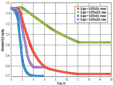 |
| FIG. 10. Influence of channeling (low gas flowrate) on residual water after regeneration. |
A case was studied using a CFD model,14 wherein the breakthrough time of aged molecular sieves was compared with a case where the regeneration flowrate was 10 times lower (in the channeling regime). Fig. 10 shows the influence of a low gas flowrate (leading to channeling) on the residual water content on the molecular sieve bed after regeneration. In the first case, a higher gas flowrate (0.13 m3/sec) is used, which results in an average residual water content of 2% (kg of water/100 kg of molecular sieve) and a maximum of 3.8% (usually observed near the wall, due to the radial temperature gradient).
In the second case, a lower gas flowrate (0.013 m3/sec) is used with a longer heating time. This results in an average residual water content of 2.6% and a maximum of 8.5% (usually observed near the wall, due to the temperature gradient). It can be deduced that using a lower gas flowrate (in the channeling regime) not only leads to a higher residual water content, but also widens the gap between the maximum and minimum residual water content across the bed that can adversely impact the performance (i.e., outlet impurity specification).
 |
| FIG. 11. Channeling during regeneration phase. |
Fig. 11 illustrates three breakthrough curves. The red curve represents the fresh molecular sieve, the green curve represents the regenerated molecular sieve with the appropriate flowrate, and the blue curve represents the molecular sieve regenerated with a low regeneration flowrate in the channeling regime. As expected, the residual water buildup with the lower regeneration flowrate was significantly higher as compared with the base case; the breakthrough time decreased by approximately 1 hr. Note: With this low regeneration flowrate (corresponding to the channeling regime), sometimes no significant reduction in residual water is seen, even with a longer heating time, especially when the regeneration pressure is very high, as shown in Fig. 10.
The obvious impact of a decreased adsorption time, which leads to an increased number of cycles, is an approximate 10% decrease in the lifetime of a molecular sieve. An approximate 5% increase of regeneration duty (due to increased heating temperature and heating time) was required to limit the impact, although not significantly.
In adsorption, if premature breakthrough is seen on only one vessel out of several vessels in parallel, it may be due to unequal flow distribution resulting from the bed configuration. Possible contributing factors are differences in bed loading amounts or dates, coking, liquid carryover, grid failure on a bed or fluidization. Unequal flow distribution can also be detected through the pressure drop across the vessels in adsorption. Fig. 12 shows a three-vessel configuration with two vessels in adsorption in parallel. The pressure drop across Vessel A is shown to be lower than that across Vessels B and C.
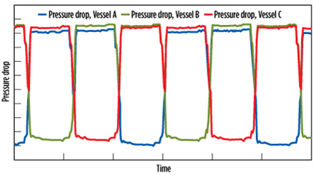 |
| FIG. 12. Unequal flow distribution shown by difference in pressure drop. |
Presence of olefins. As previously mentioned, the molecular sieve ages with time, and its capacity decreases slowly. One of the main reasons is that the porosity is partially fouled by carbonaceous components. These compounds, often referred to as “coke,” are caused by either heavy hydrocarbons (HC) present in the feed and which sometimes remain in the bed along the cycles, or by olefins (e.g., ethylene, propylene, etc.) that polymerize in contact with the molecular sieve to form long-chain polymers.
As a result of fouling, the MTZ is lengthened and the overall porosity is decreased. Normal fouling is taken into account in the unit design, among other factors that define the product aging rate. However, in some cases, fouling is more significant than anticipated, leading to premature breakthrough. The real issue is that a part of the deposit is not removed during regeneration and is subject to cracking and “polymerization.” It ultimately forms heavy, growing carbonaceous deposits that build up in the porosity,15,16 especially at zeolite acidic sites.
This problem is quite common in cracked gas drying applications, where olefins (especially ethylene) are not only present in feed, but also sometimes in the regeneration gas. The use of 3A (3-angstrom-pore) molecular sieves in such applications is, therefore, mandatory to selectively adsorb water and minimize ethylene coadsorption and the side reactions resulting from it.
In spite of this precaution, fouling of the molecular sieve still occurs, especially when ethylene is present in the regeneration gas. When ethylene comes into contact with the polar surface of the molecular sieve at high temperature, it has the tendency to open its double bond and combine with other molecules, leading to long-chain polymers. This is why the molecular sieve often appears greyish/black at the end of its lifetime in cracked gas drying applications, as shown in Fig. 13.
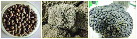 |
| FIG. 13. Molecular sieve with coking. |
The heating procedure can be adapted in such cases, depending on the concentration of ethylene in the regeneration gas. For an ethylene concentration of less than 0.5 mol%, no particular precaution is required. For a concentration between 0.5 mol% and 1 mol%, the coking damage is limited, and it is sufficient to take some design margin on the adsorption capacity during the design process. Sometimes, a decrease in regeneration temperature from 230°C to 210°C can also be helpful.
For a concentration above 1%, which tends to occur when one or two expanders are down, resulting in an ethylene concentration of 0.5%–5%, the heating procedure should be adapted. If the deviations last for only a couple of cycles, then it is recommended to regenerate at 170°C–180°C. This process will limit the ethylene reaction to polymers, but at the same time give a high residual water content in the molecular sieve bed at the end of heating. It will also reduce the adsorption capacity in the consecutive adsorption cycle, and water will continue to accumulate during approximately two more cycles. At the end of a couple more cycles, when the ethylene concentration is back to normal, an exceptional regeneration should be performed at high temperature (230°C) and a longer time. This can be repeated until all residual water is removed and the unit returns to normal operating conditions.
However, if the concentration lasts above 1 mol% for a longer duration (or, in some cases, 2 mol%–2.5 mol% can be present throughout the lifetime), in those cases, a multistep heating, as illustrated in Fig. 14, is recommended. The first step, at 100°C–120°C, is done to prevent retrograde condensation. The second step, at 170°C, lasts for the majority of the heating time and removes the bulk of the adsorbed water. The third step, at 230°C, lasts for 1 hr–2 hr and is the finishing step to decrease the residual water, especially from the MTZ, to respect the outlet specifications.
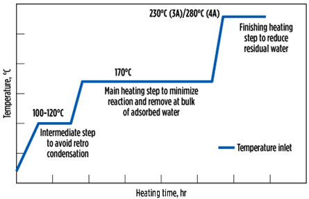 |
| FIG. 14. Multistep heating to minimize side reactions and maximizewater desorption. |
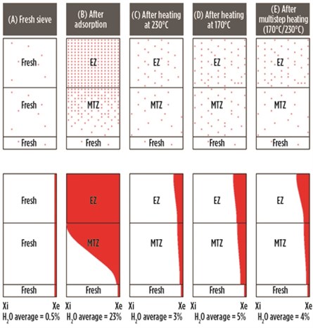
Fig. 15 illustrates the water concentration (Xi = Initial, Xe = End) inside the molecular sieve bed, in equilibrium, in the MTZ and in the fresh zone, for a new sieve (A), after adsorption (B), after heating at a high temperature of 230°C (C), after heating at 170°C instead of 230°C (D), and after multistep heating at 170°C followed by 230°C (E).
 |
| FIG. 15. Water concentration in molecular sieve as a function of the heating temperature profile. |
It can be seen that, for the new sieve, very little water is present (typically less than 0.5%) when it is delivered from a molecular sieve supplier (Case A). After the first adsorption cycle (when the adsorption capacity is at a maximum), the water content in the sieve is approximately 23%, with the equilibrium zone completely saturated (Case B). This sieve, when heated at 230°C, will desorb most of the water, and the residual water after heating is about 3% (Case C). The outlet specifications of 0.1 ppmv–1 ppmv can be easily obtained.
However, if the heating was performed at 170°C instead of at 230°C, then the higher residual water is left both in the equilibrium as well as in the MTZ, with the bed average at about 5% (Case D). This bed, when switched to adsorption, may not be able to meet a stringent specification of 0.1 ppmv–1 ppmv, and the adsorption time will decrease due to the lower adsorption capacity. This will increase the number of regenerations and reduce the lifetime.
To avoid this scenario, multistep heating is preferred, with the majority of the heating step at 170°C followed by a finishing step at 230°C. Here, the residual water is decreased both in the equilibrium and in the MTZ (more importantly in the MTZ, as the heating time at 230°C is short), giving a bed average of 4% (Case E). The advantage of this step is that the ethylene reactions are limited at 170°C, while the bulk of the water is removed. When heated at 230°C for 1 hr–2 hr, even though ethylene reactions take place, the residual water is decreased significantly, at least from the MTZ, to continue respecting the stringent outlet specifications. Fig. 16 shows the evolution of residual water in the molecular sieve over time for the preceeding five cases.
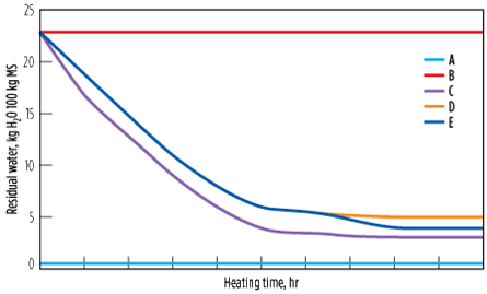 |
| FIG. 16. Evolution of residual water in the molecular sieve, with time as a function of the heating temperature profile. |
Presence of oxygen. The presence of O2, especially in natural gas from a pipeline, is sometimes reported (generally at low levels in the range of 10 ppmv–50 ppmv, but sometimes as high as 100 ppmv–1,000 ppmv). The reasons for the presence of O2 are not always obvious, and several possible explanations related to processes or equipment (e.g., compressors, pipe maintenance) are found. O2 can be present in the feed and/or in the regeneration gas, which often have the same origin.
O2 has two potential negative effects. The first includes oxidation reactions—i.e., the partial or complete combustion of HCs.17 In natural gas drying, the regeneration gas is mainly composed of methane; most of the time, a slipstream of the dried gas is used. When passing through the heater, iron oxides—which cover the steel surfaces, and are favored by the presence of O2—can catalyze the oxidation of the HCs at typical regeneration temperatures (250°C–300°C).
Once initiated, and if O2 is present, the combustion reactions continue and propagate in the vessel. Methane and O2 form water and carbon dioxide, which impact the desired final specifications by increasing the residuals in the reactivated bed. Reactions involving heavier HCs are more complex and can lead to intermediates, such as oxygenates and olefins, which ultimately form heavy coke deposits. As a result, the MTZ length and the overall adsorption capacity of the molecular sieves are rapidly affected. In serious cases, pressure drop can rapidly and significantly increase. It has been shown that up to 50% of the O2 can be converted, and that significant problems start with O2 concentrations in the feed as low as 15 ppmv–20 ppmv.
The second effect is that, in the presence of sulfur compounds like hydrogen sulfide (H2S), and even at ambient temperature, O2 forms sulfur dioxide and water, and, ultimately, elemental sulfur. This elemental sulfur is deposited in the porous structure, and clusters can form and partially block the flowrate, leading to channeling, high pressure drop and, eventually, premature breakthrough.
While the second problem is difficult to address, except by minimizing sulfur and O2 levels as much as possible, efficient answers exist for the first issue. A closed-loop regeneration scheme or the use of O2 and sulfur removal adsorbent are often cited in literature.18 However, these solutions involve high capital and operational cost, with little proof of meeting the stringent specification of 0.1 ppmv. Recommendations for the design are as follows:
- If O2 content in the regeneration gas is lower than 20 ppmv–30 ppmv, then no specific action or design margin/provision is required because the effect is not significant.
- The “grey zone” is 50 ppmv–100 ppmv. This needs to
be taken into account within a robust design. For such
a level of O2, the recommendations are as follows: - A multistep heating procedure, with most of the time spent at a temperature of 170°C, that prevents O2 conversion but allows most of the water to be desorbed. It should include a 1 hr–2 hr finishing step at the end at a higher final temperature. This will allow some of the O2 to convert, but it is still necessary to desorb water from the sieve down to low residuals that are compatible with the LNG specification.
- The use of a 3A molecular sieve is recommended because it minimizes the residual “O2 origin” water pickup on the sieve during regeneration, and also because 3A generally shows lower catalytic behavior compared to any other type of sieve.
- Some design margins need to be taken with regard to the vessel diameter (to allow a slightly higher pressure drop evolution) and the length of the MTZ.
- High values of 100 ppmv–1,000 ppmv often come from pipeline specifications. However, in reality, the values are significantly lower. These measurements can be ascertained only through analytical measurements. In the case of high values, the same recommendation must be applied. However, the total number of regeneration cycles over the lifetime should be reduced during the design process.
Presence of methanol. The presence of methanol during the adsorption phase not only generates competition for water by extending its MTZ due to the coadsorption of methanol, but it can also potentially damage the molecular sieve during the regeneration phase, as methanol has a strong tendency to form coke at a high temperature.
The recommendation for the design of the adsorption phase is to take into account the coadsorption of methanol and the eventual reduction of the MTZ for water. For the regeneration phase, two precautions need to be taken: (1) The temperature ramps need to be further decreased to 1°C/min–2°C/min, and (2) the intermediate heating step should be performed at 80°C–100°C, instead of at 100°C–120°C, for the case where only water is present.
Presence of HC retrograde condensation. Molecular sieves can be exposed to liquid HC through a phenomenon known as “retrograde condensation.” This phenomenon is difficult to diagnose, but is scientifically proven and admitted by a majority of authors.19,20,21,22
Fig. 17 shows two cases—a lean gas and a heavier one—with the corresponding phase diagrams (also known as the “PT envelope.”)15,23 It shows that a heavy gas at HC dewpoint, when operated at high pressure, can be subject to HC condensation when the pressure is decreased. For such a gas, liquids can be expected to form due to the pressure drop across the bed (see the dashed arrow in Fig. 17).
 |
| FIG. 17. PT envelope for natural gas. |
Although this can be numerically simulated, it is difficult to accurately estimate how much liquid is formed and stays in the molecular sieves’ porosity. The HC deposit blocks access to micropores, and therefore extends the MTZ, which results in an overall decrease in adsorption capacity. In addition, the heavier HC can crack and polymerize during the regeneration, thereby building up and worsening the problem. Pressure drop increases, and channeling may appear. For such gases at HC dewpoint, the most efficient solution is to preheat the inlet stream by 3°C–5°C and adapt the regeneration pressure, if required.
COS formation. When “sour” natural gas containing H2S and CO2 comes into contact with a molecular sieve, COS and water are formed.15 Normally, COS should be avoided or minimized as much as possible, with the main concern being if it converts back to H2S in the presence of water in some downstream processes, it causes corrosion problems. The higher the concentration of H2S and CO2, the higher the COS formation. The COS formation also increases with increasing temperature, pressure and residence time. However, the COS formation rate is reduced in the presence of water.
To minimize COS formation, temperature and pressure should be kept as low as possible. Lower regeneration temperature will also result in high residual water and less COS formation. This reduced temperature can be compensated by increasing the gas flowrate, which will eventually decrease the residence time and reduce COS formation. Furthermore, during the adsorption phase, the maximum bed should be utilized for water adsorption. Ideally, this is a breakthrough time operation instead of a fixed adsorption time operation. Finally, proper selection of the molecular sieve type can also reduce COS formation.
Other contaminants. A number of other contaminants15 and process deviations, like water carryover, amines carryover, acid attack, caustic attack, salts (NaCl), oils (typically from compressor lube systems), amine-based corrosion inhibitors, heavy sulfurs, glycols, etc., can potentially impact molecular sieve performance. However, little can be done to adapt the regeneration procedure when the issue needs to be addressed elsewhere in the upstream process.
Takeaway. Molecular sieves are an efficient, reliable and proven separation/purification technology. However, the adsorption and regeneration phases are complex and require precaution during design and troubleshooting. This article series focuses on the TSA processes, used in the majority of units in the oil and gas industry, where the regeneration is performed by increasing temperature.
Regeneration is the most crucial step that determines the performance and the operating cost of molecular sieves over a given lifetime. The main design principles and recommendations for the regeneration were discussed. Major parameters, including temperature, time, pressure, regeneration gas type, flow-related issues and contaminant-related issues, were addressed, along with how these parameters can be adapted under process deviations.
The recommendations in this article series will help not only EPC companies in designing new projects, but also natural gas, petrochemical and refinery operators in optimizing and troubleshooting existing units to increase their lifetime, control pressure drop, control product quality and decrease plant downtime, which will bring significant CAPEX and OPEX savings.
End of series. Part 1 of this article appeared in the January/February issue of Gas Processing. GP
Literature cited
14Jain, S., T. Boucheres, L. Gomes and A. Ghoussoub, “Use of CFD modeling to optimize capital and operational costs of molecular sieve units,” GPA Europe Annual Conference, Athens, Greece, May 2016.
15Terrigeol, A., “Molecular sieves contaminants: Effects, consequences and mitigation,” GPA Europe Annual Conference, Berlin, Germany, May 2012.
16Wang, B., “Zeolite deactivation during hydrocarbon reactions: Characterisation of coke precursors and acidity, product distribution,” PhD Thesis, University of London, UK, December 2007.
17Bancroft, W. G., K. R. Clark and G. Corvini, “Beware of oxygen during gas drying,” Hydrocarbon Processing, 1975.
18McIlroy, C. et al., “Successful mitigation of oxygen and higher hydrocarbon presence in treating pipeline natural gas for North American LNG projects,” Gas Processors Association Conference, San Antonio, Texas, April 2015.
19Eguren, R. R., “Molecular sieves operational challenges,” 62nd Laurance Reid Gas Conditioning Conference, Norman, Oklahoma, February 2012.
20Trent, R., “Dehydration with molecular sieves,” 51st Laurance Reid Gas Conditioning Conference, Norman, Oklahoma, February 2001.
21Rastelli, H. and J. Stiltner Shadden, “Extending molecular sieve life in natural gas dehydration units,” Gas Processors Association Annual Convention, San Antonio, Texas, March 2007.
22Maddox, R. N., J. H. Erbar, “Low-pressure retrograde condensation,” Oil & Gas Journal, July 1977.
23Rojey, A., et al., “Le gaz naturel production, traitement, transport,” Publication de l’institut Français du Pétrole, 1994.
 |
Sandeep Jain is a Global Technical Sales Manager at Arkema Group. He joined Arkema Group in 2009 and spent 6 yr in the acrylics business as a Process Engineer and a Projects Coordinator. He joined Arkema’s CECA Molecular Sieve Department in 2015 as Market Manager, Oil and Gas. He is now Global Technical Sales Manager for CECA’s worldwide oil and gas project activity. He is also the Global Technical Manager and Area Manager for sales in Africa. Dr. Jain’s experience includes sales, marketing and project management. Also, his strong engineering and research and development (R&D) background has led to the publication of more than 30 articles, chapters and patents. He holds a PhD in process engineering, an MS degree in process engineering and a BS degree in chemical engineering.


Comments