
Minimize flaring with modifications to flare gas recovery unit
Every refinery has a pressure relief and flare system to enable safe handling and disposal of hydrocarbon vapors and liquids. The flare gas recovery unit (FGRU) provides many benefits to the end user, including a reduction of plant fuel and steam consumption, an increase in flare tip life, a rapid return on investment, a decrease in plant emissions and a reduction in continuous flare operation.
A variety of strategies exist for minimizing flaring. These strategies include the use of plant practices and existing equipment to control processes that produce waste gases. Equipment must be properly maintained to minimize leaks into the waste gas header. Another strategy encompasses an improved understanding of how waste gases are produced under a given set of conditions, so that those conditions can be avoided.
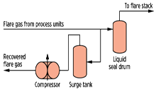
This might mean recycling waste gases back into the process or using alternative technologies that produce less waste. Another example is the FGRU (Fig. 1), which can capture waste gases that would have been flared, either for use in the plant or for sale.
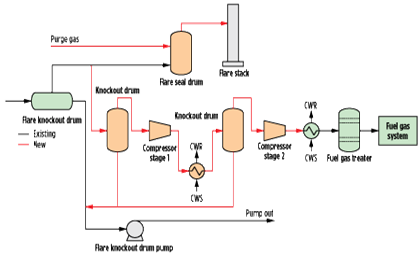 |
| FIG. 1. Typical flare gas recovery unit. |
Plant practices: FGRU study rules. The consideration of flare gas recovery in a low-pressure (LP) flare package system in a typical gas plant is discussed here. As per the utility summary for the plant, flaring is divided into two main categories: normal continuous LP flaring and intermittent flaring.
The definition of the flare gas recovery unit covers only the recovery of normal continuous flaring streams, including flash and stripping gas. Intermittent flaring includes gases flared during unexpected shutdowns or in abnormal unit operating conditions. Intermittent flaring cases (e.g., emergency depressuring in the high-pressure or medium-pressure flare) should be considered during the design of seal drums and connection facilities.
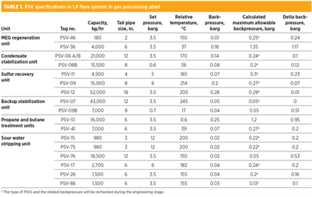
Based on the data shown in Table 1, the designer should review options for reducing backpressure. For example, backpressure should not exceed 10% of set pressure for the conventional valve; balanced or pilot valves may be considered if backpressure is excessive. Other possible remedies include making jump-overs to relieve local backpressure, replacing pipes and pressure safety valves (PSVs), running a parallel flare line, and moving a load to a different part of the flare system. The data in Table 1 may be useful for the selection of FGRUs during plant retrofitting.
 |
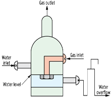 |
| FIG. 2. Seal drum schematic. |
Typical scenarios for FGRU. In Fig. 2, an FGRU with a water seal drum is shown for a hypothetical Scenario 1. The FGRU could be installed at the bottom of the flare stack or on a water seal drum located a short distance away from the flare stack. Water seals can be used only for a conventional pipe flare tip and are not compatible with a high backpressure. They must avoid discharging gas to the sewer and through the vent that is used as a vacuum breaker on the seal leg.
Water seals protect the upstream headers and flare drum against air ingress, mainly when the purge gas is stopped and particularly during maintenance. In addition to increasing the efficiency of the FGR operation, deep seal drums provide a higher level of safety in the overall system design.
If the volume of flare gas that is relieved to the flare system exceeds the capacity of the FGRU, then the pressure in the flare header will increase until it exceeds the backpressure exerted on the header by the liquid seal. In this event, excess gas volume will pass through the liquid seal drum and to the flare, where it will be burned. The seal drum should be of a similar design philosophy as that in API Recommended Practice (RP) 521. A vertical configuration may be preferable to a horizontal one, for spatial reasons. Rather than using a baffle weir and drain system, a liquid level regulation and preferential hydrocarbon skimming may be accomplished using multiple standpipes of differing heights.
Experience has shown the need for attention to vessel internals to prevent troublesome wave action of the disturbed seal fluid. Such disturbances may occur due to an excursion in flare flow that breaks the seal, or to incorrect tuning of compressor controls. In general, the compressor should be placed so that the effect of process unit shutdowns will not affect its availability. Conventional compressor control strategy calls for an adjustment to the (net) discharge flow of the compressor to maintain constant suction pressure. A suction pressure of approximately 1 psig is high enough to prevent air ingress and low enough to allow the existing relief valves to perform properly. The suction pressure is determined by the seal liquid height in the seal drum.
In a deep seal drum, the depth of the sealing fluid is designed to be equal to the staging pressure of the staged flare system. The overflow chamber can be designed to automatically flow back into the sealing chamber after the gas velocity decreases below the rate required for closing off the second stage. The depth of the liquid seal drum must be considered when calculating the relief header backpressure. The height of the liquid seal can be determined using Eq. 1:
h = 144 × p/ρ (1)
where:
h = Net height of liquid seal, ft
p = Maximum allowable header backpressure, psi
ρ = Sealing liquid density, lb/ft3.
The vessel-free area for gas flow above the liquid level should be a minimum of 3 ft, or three times the inlet pipe cross-sectional area, to prevent surges of gas flow to the flare and to provide space for disengagement. API RP 521 states that surging in seal drums can be minimized with the use of V-notches on the end of the dip leg. If the water sloshes in the seal drum, it will cause pulsations in the gas flow to the flare, resulting in noise and light disturbances. For this reason, most facilities prefer to use either a displacement seal or a perforated anti-slosh baffle.
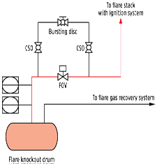 |
| FIG. 3. Fast-opening valve schematic. |
Scenario 2 describes a fast-opening valve (Fig. 3). The flare stack should be isolated from the part of the flare system where gas is recovered by a fail-open, quick-opening shutoff valve that opens only during abnormal or emergency flaring. This valve should be provided with a bypass loop containing a bursting disc, as a secondary form of protection, to avoid the flare system becoming dependent on instrumentation and valve operation.
The recovery line between the flare system and the main process should be equipped with a valve that closes when flaring gas. Where a flare gas recovery system is provided, the recovery system should be sized to accommodate the sum of the normal flow of gas into the flare or vent system (if one exists) plus the anticipated leakage from relief valves, blowdown valves and process pressure spill-off valves. The opening mechanism must react quickly and safely to handle the dynamic effects associated with the opening of blowdown valves or large relief valves. The opening mechanism must prevent excessive pressure buildup in the flare system while opening. The components considered for closure of the flare system are the actuated fast-opening valve (FOV), the bursting disc (BD) and the buckle pin valve (BPV).
The opening time for an FOV is approximately 2 sec. Once activated, the FOV remains open until it is manually reset after normal operating conditions have been reestablished. The opening function of a BPV is similar to that of a PSV; however, the BPV does not close after opening, as the guard pin is permanently buckled. The BPV has a very fast reaction. Also, the distribution of activation pressure is quite narrow and is therefore considered suitable as a first level of protection in addition to the active device.
The BD is extremely fast-opening, but it suffers from a relatively wide distribution of the actual bursting pressure. Replacement of the BD after activation requires isolation of the BD fixture from the system pressure by closing the block valves. The BD rupture pressure is less defined compared with a BPV. Not only is the BD more complicated to change out when activated, but it is also considered to be more suitable as a second level of protection to the active device.
The BPV should be set as low as possible without being activated by the regular dynamic behavior of the system. The BD should be set as high as possible to prevent activation and simultaneously avoid overpressure of the closed part of the flare system. Continuous purge, normally by nitrogen, is required downstream of the FOV when it is closed to prevent air ingress into the main flare stack, and also to remove any residual, unburned hydrocarbon gas.
 |
| FIG. 4. Location of compressor in an FGRU. |
Compressors in FGRU package. Sliding vane compressors operate with a variable speed drive unit and, therefore, offer high efficiency. The location of a compressor in an FGRU package is shown in Fig. 4. A sliding vane compressor can include a built-in 3:1 turndown. The maximum outlet pressure for sliding vane compressors is approximately 150 psig, and the heat of compression is passed into the gas, so gas after-cooling is required. The advantages of sliding vane compressors lie in their efficiency (approximately 65%–75%), their low power usage and their flexibility of operation.
Liquid ring compressors are the industry standard for FGR systems. They are well-suited for discharge pressures up to approximately 150 psig, but their efficiency is not as high as other technologies at approximately 25%–30% of full load. These compressors work by mixing gas with liquid (normally water) and, therefore, require a separation vessel post-compression. These compressors have the advantage of being able to accept some liquids and particulates in the gas. Additionally, they operate at relatively low speeds and have low maintenance demands.
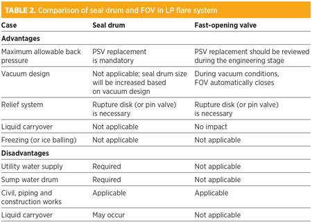 |
Water seal drum or FOV. The advantages and disadvantage of seal drums and FOVs are shown in Table 2. GP
 |
Hamid Reza Kalat Jari is Head of the process department at Sazeh Consultants in Tehran, Iran. He has worked at the Sazeh process department for more than 16 yr. Previously, he worked at Total Fina Elf and National Iranian Gas Co.
 |
Ali Borhani is the Lead Process Engineer in the process department at Sazeh Consultants. He has worked at the Sazeh process department for more than 5 yr. Previously, he worked at Iranian Oil & Gas Co.


Comments