
Challenges and opportunities for equation-based hydrates prediction
Gas hydrates may form in any location where free gas, water, and the appropriate temperature and pressure exist, such as in natural gas production, transportation and processing systems. Hydrates may form and partially or completely constrict the gas flowrate in the well bottom zone of a layer; in the fountain tubing column or the annular space of a well bore; in well top pipes or near well top equipment; in field pipelines and installations; in transport gas pipelines and product pipelines; or in underground gas storage systems.
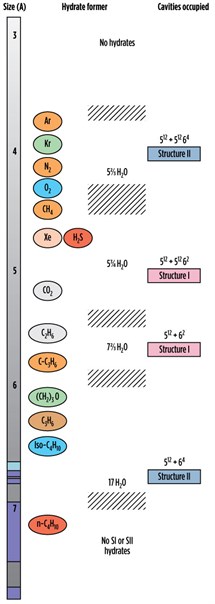 |
| FIG. 1. Comparison of guest molecule sizes and cavities occupied.3 |
The cost to the hydrocarbon processing industry to mitigate the formation of gas hydrates is estimated to represent 5%–8% of total plant cost. In a survey of 110 companies, flow assurance was listed as the biggest problem in offshore energy development. Deep Star, a consortium of companies focused on Gulf of Mexico deepwater development technology issues, has concluded that replacement of hydrates-plugged lines in deepwater environments may cost an average of $1 MM/mi.1
This article explains the various methods of hydrates prediction, and examines empirical equations with experimental data and hydrates formation conditions during gas expansion. It also outlines the technical challenges of predicting hydrates formation conditions.
Hydrates background. Gas hydrates are solid crystalline compounds wherein guest molecules are trapped, in a cage-like framework of the host molecules, without forming a chemical bond. As a result of its hydrogen (H2) bond, water can form hydrates. The H2 bond causes water molecules to align in regular orientations. The presence of certain compounds causes the aligned molecules to stabilize, and a solid mixture precipitates.
The water molecules are referred to as the host molecules, and the other compounds, which stabilize the crystals, are called the guest molecules. The hydrates crystals have complex, three-dimensional structures in which the water molecules form cages. The guest molecules are trapped in these cages. The stabilization resulting from the guest molecule entrapment is thought to be caused by Van der Waals forces, which describe the attraction between molecules that is not the result of electrostatic attraction. The H2 bond is different from Van der Waals forces in that it is attributed to strong electrostatic attraction; however, some still classify the H2 bond as a Van der Waals force.
No bonding occurs between the guest and host molecules in gas hydrates. The guest molecules rotate freely inside the cages built up from the host molecules. This rotation has been measured by spectroscopic means. No hydrates without guest molecules have been found in nature.
Clathrates (inclusion compounds) are stabilized by the weak attractive interactions between the guest and water molecules. However, the guest species have size restrictions. This arises from the fact that there are a limited number of cage types that encapsulate guest molecules without deviation of the ideal H2 bond lengths and angles. The cages are not necessarily dependent on the temperature and pressure of the guest compound being in equilibrium with clathrate hydrates.2,3
The formation of hydrates requires three prerequisites:
- Low temperature and high pressure
- Presence of hydrates formers, such as CH4, C2H4, CO2 and H2S
- A sufficient amount of water.2
Hydrates structures.4 The possible types of hydrates structures are described in the following sections.
Structure I gas hydrates are formed when cavities link together through their vertices. Since dodecahedra are unable to pack together precisely, a tetradecahedron—a polyhedron with 12 pentagonal and two hexagonal faces—is created. Oxygen (O2) atoms of these water molecules are arranged in such a manner that two pentagonal dodecahedra and six tetradecahedra are formed.
Each tetradecahedron has a cubic cell constant of 12°A. Forty-six molecules of water constitute the unit cell, two of which are small and contain only one guest molecule. The other six cavities can house relatively larger molecules.
Structure I gas hydrates have a simple structure, made from two types of cages—a dodecahedron and a tetradecahedron. A dodecahedron is a 12-sided polyhedron where each face is a pentagon. A tetradecahedron is a 14-sided polyhedron with 12 pentagonal faces and two hexagonal faces. Dodecahedron cages are smaller than tetradecahedron cages.
Stable hydrates can form without a guest molecule occupying all of the cages. The degree of saturation is a function of temperature and pressure. The actual composition of hydrates is not the theoretical composition. The theoretical formula for hydrates is X × 5 (3/4H2O), where X is the hydrates former. If the guest molecules occupy only large cages, then the formula for hydrates is X × 7 (2/3H2O).
Structure II gas hydrates are formed when the pentagonal dodecahedron cavities link together through face sharing. As a result of this arrangement, a hexadecahedron—a polyhedron with 12 pentagonal and four hexagonal faces—is created.
The hexadecahedron has a cubic cell constant of 17°A, and 136 water molecules are associated in each cell. These form 16 small and eight relatively large cavities. A hexadecahedron is constructed from two types of cages—a dodecahedron cage and a hexadecahedron cage. Dodecahedron cages are smaller than the tetradecahedron cages.
If the guest molecule occupies all of the cages, then the theoretical formula for hydrates is X × 5 (2/3H2O), where X is the hydrates former. If the guest molecule occupies only large cages, then the theoretical composition is X × 17H2O.
Structure H gas hydrates are less common than either Structure I or Structure II hydrates. Structure H hydrates require small molecules, such as methane and a type H former. They are constructed of three types of cages—a regular dodecahedron; an irregular dodecahedron with three square faces, six pentagonal faces and three hexagonal faces; and an irregular icosahedron, a 20-sided polyhedron with 12 pentagonal faces and eight hexagonal faces. A Structure H hydrate contains 34 water molecules.
The theoretical formula is Y × 5X × 34H2O. Here, X represents the small molecule that enters only small cages, and Y represents the large molecule that enters only large cages. In Structure H hydrates, the largest cage can accommodate up to five argon atoms.
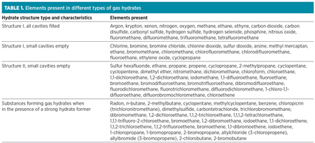 |
Fig. 1 shows a comparison of guest molecule sizes and cavities occupied.3 Table 1 lists the elements present in different types of gas hydrates.
Hydrate prediction. The following sections explain the various methods of hydrates prediction for different kinds of gas hydrates.
Gas gravity method. The gas gravity method (Fig. 2) is used to predict gas hydrates forming conditions. This method is mentioned in the Gas Processors Suppliers Association (GPSA) Engineering Data Book. The GPSA gas gravity method is accurate up to 65°; beyond that, it slightly overestimates the temperature.
 |
| FIG. 2. The gas gravity method of hydrates prediction.5 |
Gas gravity is defined as the molecular weight of the gas divided by the molecular weight of air. To use this chart, the gas gravity is calculated for the lowest temperature of the pipeline or the process specified. The pressure at which hydrates form is read directly from the chart at the appropriate intersection of gas gravity and temperature.
The chart is available for gas gravities of 0.6 to 1. If the point is on the top left side of the graph for the corresponding temperature, pressure and gas gravity, then it is in the hydrates region. If the point falls on the right side of the graph, then it is in the hydrates-free region.
This method does not indicate the type of hydrates, however. It considers only the gas gravity of the components. If two components have equal molecular weights, such as butane and isobutane, then the method may estimate the same hydrates formation temperature or pressure, even when the hydrates are of different types.
B. F. Towler and S. Mokhatab developed an equation (Eq. 1) based on the gas gravity chart that predicts the hydrates forming temperature, where P is pressure and GG is gas gravity:5
Th = 13.47 log (P) + 34.27 log
(GG) – 1.675 [log (P) × (1)
log (GG)] – 20.35
K-Factor method. Wilcox et al.’s K-Factor method3,7 is based on distribution coefficients (Ki values) for components on a water-free basis. It is accurate for pure components and cannot predict hydrates for liquids. This method is limited to hydrates-formation pressures up to 28 MPa (4,000 psia) for methane, ethane and propane; up to 14 MPa (2,000 psia) for isobutane and hydrogen sulfide; and up to 7 MPa (1,000 psia) for carbon dioxide. In general, the recommended use of this method is 0 < T > 20°C, 0.7 < P > 7 MPa.
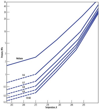
Baillie-Wichert method. The Baillie-Wichert method6,7 is a graphical method used for gas gravities between 0.6 and 1. This method accounts for the presence of H2S (up to 50%) and propane (up to 10%). The chart (Fig. 3) estimates the hydrates formation temperature within 1.7°C, giving an advantage over the gas gravity and K-Factor methods in that it can be used for sour gases.
 |
| FIG. 3. Estimate of hydrates-formation temperature within 1.7°C. |
Hammerschmidt method. The Hammerschmidt method8 gives a good prediction with low temperature and pressure. It is used as an initial value for the prediction of hydrates condition, as described in Eq. 2:
Th = 8.9 P0.285 (2)
Motiee method. The recommended use of the Motiee method9 (Eq. 3) is when the gas gravity is less than 0.65 and the temperature is greater than 60°F at pressures greater than 2,000 psi:
Th = –238.24469 + 78.99667 log
(P) – 5.352544[log (P)]2 + 349.473877 (GG) – (3)
150.854675 (GG)2 – 27.604065[log(P)] (GG)
Berge method. The Berge method8 is used to predict hydrates-forming temperatures with Eqs. 4 & 5:
For 0.555 ≤ GG < 0.58: Th = –96.03
+ 25.37 × ln P – 0.64 × (ln P)2
+ (GG – 0.555) ÷ 0.025 ×
[80.61 × P + 1.16 × 10⁴ ÷ (4)
(P + 596.16) – (–96.03 +
25.37 × ln P – 0.64 × (ln P)2)]
For 0.58 ≤ GG < 1: Th = {80.61 ×
P – 2.1 × 10⁴ – 1.22 × 10³ ÷
(GG – 0.535) – [1.23 × 10⁴ + (5)
1.71 × 10³ ÷ (GG – 0.509)]} ÷
{P – [(–260.42 – 15.18 ÷
(GG – 0.535)]}
Some researchers recorded bad performance with increased GG when the temperature was less than 50°F and the pressure was less than 200 psi. The Berge method gives better prediction when the GG is equal to 0.555.
The Makogon method. Makogon developed a correlation based on the GG for hydrates prediction, as shown in Eqs. 6–8:
ln P = 2.3026β + 0.1144 (T + KT2) (6)
Where β = 2.681 – 3.811 γ +
1.679 γ2 (7)
K = –0.006 + 0.011 γ + 0.011 γ2 (8)
where P = pressure in Pa, T = temperature in degrees Kelvin and γ = GG.
The Kobayashi method. Kobayashi et al. developed a correlation based on the GG for hydrates prediction. It is not recommended for use above 62°F, above 1,500 psia or above a GG of 0.9. The correlation is shown in Eq. 9:
T = 1 ÷ [A1 + A2 (ln γg) + A3 (ln P) + A4 (ln γg)2 + A5 (ln γg) (ln P) +
A6 (ln P)2 + A7 (ln γg)3 + A8
(ln γg)2 (ln P) + A9 (ln γg) (9)
(ln P)2 + A10 (ln P)3 + A11
(ln γg)4 + A12 (ln γg)3 (ln P) +
A13 (ln γg)2 (ln P)2 + A14 (ln γg) (ln P)3 + A15 (ln P)4]
where A1 = 2.7707715 × 10⁻³; A2 = –2.782238 × 10⁻³; A3 = –5.649288 × 10⁻⁴; A4 = –1.298593 × 10⁻³; A5 = 1407119 × 10–3; A6 = 1.785744 × 10⁻⁴; A7 = 1.130284 × 10⁻³; A8 = 5.9728235 × 10⁻⁴; A9 = –2.3279181 × 10⁻⁴; A10 = –2.6840758 × 10⁻⁵; A11 = 4.6610555 × 10³; A12 = 5.5542412 × 10⁻⁴; A13 = –1.4727765 × 10⁻⁵; A14 = 1.3938082 × 10⁻⁵; A15 = 1.4885010 × 10⁻⁶; and where P = Pressure in Pa, T = Temperature in degrees Fahrenheit and γg = GG.
It is recommended that all of the equations be tested with experimental values.
Hydrates formation during sudden expansion.5 During sudden gas expansion, gas experiences the Joule–Thomson (JT) effect. Gas expansion charts are available for various GGs that encourage hydrates formation conditions. For a pressure greater than 6,000 psia, natural gas warms up during the sudden expansion. Fig. 4 and Fig. 5 show gas expansion charts for a 0.6-gravity and 0.7-gravity natural gas.10
Specifications of the hydrates formation, as shown in Fig. 4, include:
- Initial pressure = 1,500 psi
- Molecular weight = 17.8763
- Final pressure = 600 psia
- Initial temperature = 100°F
- Carbon dioxide = 0.02
- Methane = 0.86
- Ethane = 0.06
- Propane = 0.03
- i-butane = 0.005
- n-butane = 0.005
- H2S = 0.02
The hydrates will not form at the final condition of temperature and pressure, but they will form below 500 psia. If the initial temperature is higher than 110°F, then hydrates will not form even at atmospheric pressure, since the isotherm of 110°F does not intersect the 1,500-psia line.
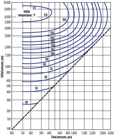 |
| FIG. 4. Gas expansion chart for a 0.6-gravity natural gas. |
 |
| FIG. 5. Gas expansion chart for a 0.7-gravity natural gas. |
Role of hydrates structure in prediction. In all three hydrates structures, each cavity can contain a maximum of one guest molecule at normal pressure. At high pressure, nitrogen, hydrogen, methane and argon can multiply and occupy the larger cavities of Structure II hydrates. Note: At normal pressure (i.e., less than 30 Mpa at approximately 260K–290K), molecules below 3.5°A become too small to stabilize any cavity; whereas molecules above 7.5°A are too large to fit into any cavity of Structure I or Structure II hydrates.
Some molecules, such as propane and isobutene, can stabilize only the larger cavities of Structure II hydrates. When a molecule stabilizes the small cavities of a structure, it will also enter the large cavities of that structure. It is known that the smallest guest molecules (Ar, Kr, N2 and O2) form Structure II hydrates, rather than Structure I hydrates.
The addition of a small amount of a second, larger hydrocarbon sometimes has a dramatic effect on the hydrates formation pressure. For example, pure methane forms hydrates with pure water at 280.4 K and 5.35 MPa; yet, hydrates are formed at 3.12 MPa with 99% CH4 plus 1% C3H8. The pressure decrease is caused by a hydrates crystal change from Structure I (with pure methane) to Structure II (with 99% methane plus 1% propane).
With a crystal structure change, a significantly different thermodynamic state (three-phase temperature and pressure) is required for stability. Propane fits only into the 512 × 64 cavity of Structure II hydrates. C3H8 is too large to occupy any other cavity.
For CH4, the diameter ratio in the 512 cavities of Structure I hydrates (0.86) and Structure II hydrates (0.87) differ by 1.5%. Pure methane is stabilized in Structure I hydrates only by the additional stability of molecules in the 512 × 64 cavity, with a small amount of propane to encourage the stability of Structure II hydrates.
The similar size ratios of methane in the 512 cavities and the large degree of stability that propane provides (0.94) to the large cages of Structure II hydrates enable a structure transition. Therefore, the concept of a guest-to-cavity-size ratio (and hydrates structure change) can provide molecular comprehension of a substantial decrease in equilibrium pressure required for a small composition change.
The Structure II stability from a small amount of propane encourages most natural gases to form Structure II hydrates, because most reservoirs contain small amounts of propane. Gas mixtures of methane and ethane form Structure II clathrate hydrates in certain composition ranges, despite the fact that pure methane and pure ethane gases normally form Structure I hydrates. Methane and ethane mixtures form more stable hydrates for three reasons:
- Empty Structure II hydrates have a lower chemical potential value than empty Structure I hydrates
- The ratio of the number of larger cages to the number of water molecules for Structure I hydrates is much larger than
that for Structure II hydrates - The free energy of the larger cage occupancy for Structure II hydrates is lower than that for Structure I hydrates, for both methane and ethane.
The first and third factors contribute to the stabilization of Structure II hydrates, while the second factor contributes to stabilizing Structure I hydrates. The preferential structure for a given condition is determined by the competition among these three factors.
As one illustration, simple hydrates of C3H8 and i-C4H10 have a similar ∆Hd of 129 and 133 KJ/mol because they occupy the 512 × 64 cavity, although their size-to-cavity ratios are somewhat different (0.94 and 0.98). The similarity of ∆Hd is remarkable, but it is principally due to the occupation of the 512 × 62 cavity. Similarly, C2H6 (∆Hd = 72 KJ/mol) and CO2 (∆Hd = 73 KJ/mol) are in the 512 × 62 cavity. CH4 and H2S (∆Hd within 3% of each other) occupy both 512 and 512 × 62 as simple hydrates.
The mixture of C3H8 plus CH4 has a value of ∆Hd = 70 KJ/mol over a wide range of composition. In such mixtures, C3H8 occupies most of the 512 × 64 cavities, while CH4 occupies only a small number of 512 × 64 and possibly 512. Most natural gases (which commonly form Structure II hydrates) have similar values of ∆Hd. Note: Mixtures that fill both types of Structure II cavities have a lower value of ∆Hd (79 KJ/mol) than components such as C3H8, which fill only the 512 × 64 cavity (∆Hd = 129 KJ/mol).
Similarly, over a wide range of compositions of methane and ethane, ∆Hd values are similar (74 KJ/mol) for components entering both cavities of Structure I hydrates. Identical arguments may be used to explain similar ∆Hd values of 79.5 KJ/mol +/– 7 KJ/mol for Structure H binary mixtures with methane, since all three cavities are occupied.
From the above, it was found that less energy is required to dissociate hydrates structures with both cavities filled than those with one cavity filled. It has been suggested that collisions of the guest molecules with the cavity wall weaken interactions between the hydrogen bonds, which is also reflected in a high value of thermal expansion. To a fair engineering approximation, ∆Hd is:
- A function not only of the hydrogen bonds in the crystal, but also of cavity occupation
- Independent of guest components and mixtures of similar-size components within a limited size range.
Limitations of empirical/graphical hydrates prediction. The preceding hydrates prediction strategies are characterized by a number of limitations:
- The equations and graphs do not provide details about the three hydrates structures themselves.
- The equations and graphs do not provide details about the cage occupancy; however, the occupancy ratio shows different trends at different pressure and temperature conditions.
- Hydration number—the number of water molecules in the hydrates per guest molecule—are not explained by the equations.
- Binary hydrates, ternary hydrates, multi-component hydrates, single-component hydrates, hydrates in black oil, hydrates in gas condensate and Structure H hydrates are not addressed by these equations.
- Structural transitions are not addressed in these equations. For example, nitrogen hydrates can form both Structure I and Structure II hydrates. Nitrogen will occupy the large cages of Structure I and Structure II hydrates. Benzene is a very large molecule and, therefore, cannot form Structure II hydrates without the presence of a helper molecule, such as methane.
- Molecular shape is not considered. For example, xenon is a spherical molecule. Xenon hydrates do not form beyond 3,800 bar pressure; however, hydrates do form at
356K and 8,578 bar. - Retrograde behavior is not addressed.
- The equations do not consider the inhibitor type—i.e., the natural inhibitor associated with well fluids, such as brine and salts.
- The equations do not consider the presence of surfactants.
- Transient fluid flow conditions and environmental factors are not considered.
Prediction challenges. Several hydrates thermodynamic areas exist for which data are urgently needed to make accurate predictions:
- At higher process pressures, the database will require pressures higher than 10,000 psia. Generally, the hydrates database stops at 4,000 psia.
- Many gases contain considerable amounts of acid gases, carbon dioxide and hydrogen sulfide. Insufficient data have been obtained on acid gas systems for an accurate comparison of prediction programs. Especially lacking is water content data for acid gases in equilibrium with hydrates, without free water.
- More black oil data is needed.
- No hydrates phase fraction data is available in the literature against which to compare these predictions.
Future directions. The authors suggest several directions for future clarification and study of gas hydrates prediction methods:
- The effects of subcooling, agglomeration rates (i.e., mechanical agglomeration, fast sintering via continued freezing, slow sintering via diffusion), additives and corrosion inhibitors are not yet completely understood by the scientific community.
- In the case of gas-liquid multiphase flow, the effects of solids in hydraulics (e.g., pressure drop, liquid holdup, gas-liquid flow regime) call for a detailed study.
- The misting droplet deposition rate, size and effect of the presence of liquid hydrocarbons, and the relationships between these factors, must be studied in further detail.
- In the case of slurry flow, the rheological study of the relationship between viscosity vs. crystal shape, size and volume fraction, with respect to hydrates formation and growth, must be studied.
- In the case of solid flow regimes, the impacts of cohesion and plug formation via slugging dropout and pickup must be studied.
- • The impact of condensed water vs. produced water, rust, sand or asphaltenes must be studied, along with emulsification.
- The role of biology must be studied.
- In the case of pump hydraulics, the enhanced breakage rate, the different agglomeration due to differing turbulence, the impacts of increases in pressure drop, the impacts of constant rate vs. constant pressure pumping, and the impacts of materials of construction must be studied.
Due to the dearth of information available on these subjects, hydrates prediction can become complex and inaccurate.
Recommendations. During their investigation, the authors found that none of the empirical equations predicted hydrates formation conditions accurately. The Motiee method predicts hydrates formation conditions with less error, with the exception of propane hydrates. The Motiee method was most accurate at a gas gravity of less than 0.65, a temperature greater than 60°F and a pressure greater than 2,000 psi.
The Hammerschmidt method slightly overestimated the hydrates-formation conditions for methane and propane hydrates, resulting in a wide deviation from the experimental results. In the case of ethane hydrates, the Hammerschmidt equation gave various degrees of deviation with respect to various pressure tests. This equation resulted in high degrees of error for propane hydrates.
The Makogen equation showed a mixed response (underestimates and, in some cases, overestimates), and the degree of error was quite high. B. F. Towler’s correlation, based on the GPSA’s GG chart, largely overestimated hydrates formation conditions in all cases.
The Berge method also largely overestimates hydrates formation conditions. It usually showed poor performance with increasing GG, a temperature of less than 50°F and a pressure of less than 200 psi. However, it gives better performance when the GG is equal to 0.55.
Kobayashi’s equation largely overestimates hydrates formation conditions in all cases.
Hydrates formation conditions have been predicted with the use of GPSA gas expansion charts, which have their own pressure and GG limitations. With careful selection of empirical equations, these equations can be used for the initial estimation of hydrates-formation conditions. GP
Literature cited
- Welling and Associates, “Flow assurance still leading concern among producers,” Offshore, October 2000.
- Taylor, C. E. and J. T. Kwan, Advances in the Study of Gas Hydrates, Kluwer Academic Publishers, New York, New York, 2004.
- Sloan, Jr., E. D., Clathrate Hydrates of Natural Gases, 2nd Ed., CRC Press, Boca Raton, Florida, January 1998.
- American Petroleum Institute, Technical Data Book, 6th Ed., 1997.
- Tower, B. F. and S. Mokhatab, “Quickly estimate hydrate formation conditions in natural gases,” Hydrocarbon Processing, April 2005.
- GPSA, GPSA Engineering Data Book, 11th Ed., 1998.
- Carrol, J. J., Natural Gas Hydrates: A Guide for Engineers, Gulf Professional Publishing, 2003.
- Fattah, K. A. A., “Evaluation of empirical correlations for natural gas hydrate prediction,” Oil and Gas Business, 2004.
- Motiee, M., “Estimate possibility of hydrates,” Hydrocarbon Processing, July 1991.
- Elgibaly, A. A. and A. M. Elkamel, “A new correlation for predicting hydrate formation conditions for various gas mixtures and inhibitors,” J. of Fluid Phase Equilibria, Vol. 152, 1998.
 |
Chandragupthan Bahubali is a Principal Process Engineer at WOOD AMEC Foster Wheeler Ltd. He has more than 14 yr of post-graduate experience on oil and gas projects. He holds an MS degree in refining and petrochemical engineering from the University of Petroleum and Energy Studies in Dehradun, India, and a BS degree in chemical engineering from Madras University in Chennai, India. He has authored a number of articles on flow assurance, gas hydrates, fixed-bed reactors and economics.
 |
Ashwin Gopalan is a Process Engineer at WOOD AMEC Foster Wheeler Ltd. He holds a BS degree in chemical engineering from the National Institute of Technology in Tiruchirappalli, India. His areas of interest include mathematical modeling, simulation, and the process design of heat exchangers and special-case depressurization and vent systems. He has presente papers at national symposiums on the sustainability of natural resources.
 |
Girish Babu Nounchi is a Senior Pipeline Engineer at WOOD AMEC Foster Wheeler and Partners Engineering Co. in Al-Khobar, Saudi Arabia. He has more than 12 yr of post-graduate experience in oil and gas pipelines. He holds an MS degree in pipeline engineering from the University of Petroleum and Energy Studies, and a BS degree in mechanical engineering from Andhra University in Visakhapatnam, India. He has published a number of papers on flow assurance and gas hydrates.


Comments