
Surfactant contaminants in feed gas streams to amine units—The phantom foaming agent
Contamination in feed gas streams to processing plants is a leading cause of lost revenue, upsets and low throughput. More detailed testing shows that surfactants in the gas stream are among the most damaging contaminants affecting the process. Surfactants pose a number of challenges, such as foaming and emulsification. In the feed gas, surfactants may be the predominant cause of amine foaming leading to high H2S in the treated gas and amine solvent losses.
Surface active contaminants in gas streams should be sampled, analyzed and removed to enable processing plants to run in a stable manner. Here, several cases are discussed where inlet gas sampling revealed the presence of surfactants directly linked to amine solvent foaming and associated losses. Specialized methods for detecting the presence of surfactants, such as surface tension and surface rheology evaluation, are examined, along with techniques for onsite sampling of the inlet gas. Measures are also outlined to remove surfactants and eliminate their downstream effects.
Surfactant contaminants. Surfactants may be present in the gaseous phase, water, or hydrocarbon dissolved and entrained in the feed gas. When these surfactants go to processing units (e.g., amine units) or dehydration units, they can cause a number of detrimental effects, predominantly foaming. Foaming can lead to several secondary problems, such as the inability to meet specifications and/or solvent carryover. One of the most common and difficult challenges in processing units is dealing with the various forms of surfactant ingression into the system.
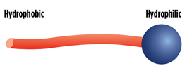
Surfactants are interfacially active molecules. They generally consist of a polar section (head), or a group and a non-polar group that are made up of hydrocarbon chains (Fig. 1). The polar part of the molecule can interact with polar solvents like water, and is called the hydrophilic portion. The non-polar part can interact with non-polar materials, such as hydrocarbons, and is called the lipophilic or hydrophobic portion.
 |
|
FIG. 1. Example of a molecular surfactant. |
Surfactants can be classified according to the charge of their polar head group:
- Anionic surfactants have a negatively charged head group
- Cationic surfactants have a positively charged head group
- Zwitterionic surfactants have a zwitterionic head group (positive and negative charge)
- Nonionic surfactants have an uncharged polar head group.
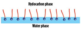
Surfactants adsorb preferably at interfaces, where they find the most energetically favorable conditions because of their two-part structure. At a water surface, for example, the surfactants orient themselves in such a way that the head group resides in the water and the hydrocarbon chain points to the gaseous phase (Fig. 2). As a result, surfactants can “mediate” between two phases, as they can form strong interactions with both of them. The interfacial tension consequently decreases. The addition of surfactants facilitates the mixing of nonpolar and polar phases. This phase mixing is used in the detergent industry, for example.
 |
|
FIG. 2. Example of surfactants populating a hydrocarbon/water interface. |
Examples of some surfactants commonly found in processing feeds, such as those from the amine unit and dehydration unit feed gas, include lubrication oils and upstream process additives. Lubrication oils for gas compressors typically contain a heavy base oil (usually petroleum fractions, called mineral oils) and a small amount of chemical additives for various functions. These additives often have surface active properties. Additives that deliver reduced friction and wear; increased viscosity; improved viscosity index; and resistance to corrosion, oxidation, aging, and contamination in upstream processes, often have surface active properties. However, upstream process additives can also be biocides, corrosion inhibitors, H2S scavengers or paraffin inhibitors, to name a few.
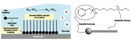
Corrosion inhibitors (filming amines or quaternary ammonium salts with alkanol segments) are an example of process additives with surface active properties. Fig. 3 shows how a filming amine performs, and a possible general molecular structure. As with surfactants in general, a filming amine has a hydrophobic section (a long alkyl chain “tail”) and a hydrophilic section (a polar ionic center “head”).
 |
|
FIG. 3. Example of the mechanism of a filming amine, such as a quaternary ammonium salt (cationic corrosion inhibitor) (left). General structure of a potential filming amine corrosion inhibitor (right). |
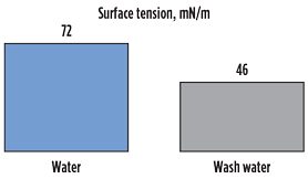
To illustrate this point, Fig. 4 shows the change in surface tension of distilled water compared to distilled water when contacted with a lubrication oil from a compression system. The decrease in surface tension from 72 mN/m to 46 mN/m is a clear indication of the surfactant properties of water-soluble additives in the lubrication oil. Similar effects are observed with some upstream process additives. The decrease in surface tension leads to an increase in entrained water and dissolved contaminants downstream as separation equipment loses liquid removal efficiency. Poor liquid removal efficiency leads to downstream impacts, including foaming caused by an elastic drain foam film, and secondary effects, such as solvent losses and performance decay.
 |
|
FIG. 4. Surface tension of pure water in comparison with water contacted with a compressor lubrication oil. |
Amine unit solvent foaming. When gas travels across the amine solvent inside the amine unit contactor (or regenerator) and gas pockets or bubbles cannot break the liquid-vapor interfacial structure, they become encapsulated in the liquid phase and form what is commonly referred to as foam. Foam is essentially a gas bubble that will not collapse and release the gas contents because of the surrounded liquid film.
To understand foam, two different aspects must be considered: foam tendency and foam stability. Foam tendency refers to the ease with which liquid film will encase gas bubbles. Foam stability is related to the elasticity of the liquid layer around the gas bubble and the likelihood that it will resist rupturing. The gas bubble has an interfacial layer or skin that confers resistance of the gas bubbles to collapsing, enabling the liquid film around it to flex as the gas bubble deforms, expands or contracts.
When an amine unit has a solvent experiencing high foaming tendency and high foam stability, foam is initiated when process perturbations occur beyond that which the unit can tolerate. A decrease in surface tension will increase the foaming tendency, such as when some hydrocarbons are present. The foam is short-lived and, in most cases, is unnoticed. However, surfactants can increase foam stability and foaming tendency. When foaming occurs, a number of operational changes may be observed:
- Differential pressure increases across the contactor and/or regenerator
- Decrease in contactor and/or regenerator bottoms level
- Temperature bulge changes position inside the contactor tower
- Amine solvent is entrained with the treated gas, leading to amine solvent losses
- Increase of H2S and reduction of CO2 in the treated gas
- Amine contamination in regenerator reflux water.
Foaming of the amine solvent can often lead to carryover from the contactor or regenerator, as well as entrained liquids in the treated gas or acid gas. Most amine units will have a separation vessel, such as a knockout drum, at the contactor outlet to remove most of the amine solvent carryover. If the amine unit is for liquid service, then foam is replaced by emulsification of the liquid hydrocarbon and the amine solvent. Any carryover from the amine contactor into the knockout drum is followed by a water wash stage to remove any emulsified amine solvent present in the treated liquid hydrocarbon.
Amine solvent carryover can also reach a number of downstream units, such as dehydration plants, mercaptans removal plants and caustic treaters. In some cases, the amine solvent carryover can ingress into the main fuel gas system. Foaming in a regenerator is also detrimental, as rich amine solvents do not regenerate properly. In addition, carryover with the acid gas can reach the sulfur recovery unit, flare systems or other downstream processes.
Antifoam addition is a common method to control the presence of foam. However, the effectiveness of antifoams can be questionable, as amine units use antifoam and experience little to no effect in foam minimization.
Some plants actually introduce antifoam to the amine unit on a daily basis, bringing short-term benefits but also long-term harm to the amine solvent. Antifoams should not be used on a constant basis, and root-cause analysis of foaming and elimination of the source of foaming are the best ways to deal with a foaming amine solvent. Nevertheless, antifoams are still a valuable tool when sporadic foaming incidents occur.
Amine solvent foaming can have a number of root causes. Often, more than one root cause takes place simultaneously. The most prevalent causes of amine solvent foaming include:
- Ineffective inlet separation leading to contaminant bypass as a result of:
- Deficient inlet separation vessel design, generally gas coalescers
- Ineffective internals or sealing surfaces in inlet separation vessels
- Errors in the instrumentation around the inlet separation vessels
- Damage to the inlet separation vessel interior
- High velocity inside the amine unit contactor (mechanical foaming or frothing)
- High concentration of suspended solids in the amine solvent (some solids can stabilize foam)
- Highly soluble iron in the lean amine (rapid solids formation in the contactor)
- Excess antifoam injection (excess antifoam use can induce foam)
- Incorrect antifoam (some antifoams will actually cause foam)
- Hydrocarbon condensation inside the contactor (lowering surface tension of the amine solvent)
- Incorrect activated carbon (activated carbon exposed to phosphorous-based activation)
- Ingression of gas-phase hydrocarbons with the feed gas (BTEX or methanol)
- Ingression of liquid contaminants (lubrication oils from compressors)
- Surfactant-based chemicals from upstream treating (such as corrosion inhibitors)
- Contaminants present in the new amine solvent or makeup water.
Note: Amine solvent foaming can be eliminated or greatly reduced in severity and/or frequency if efficient inlet separation is in place upstream of the amine contactor. In addition, it is necessary to have efficient amine solution filtration, effective activated carbon adsorption beds, and correct operations and maintenance.
Case 1: Inlet liquids contamination and amine losses. A facility for LNG production was experiencing problems with amine liquids carryover into the downstream molecular sieve unit for dehydration. The plant uses the amine unit to condition the gas for dehydration and liquefaction. Liquids carryover was evident from the high concentration of amine observed in the gas stream in the downstream separators and the molsieve inlet vessels.
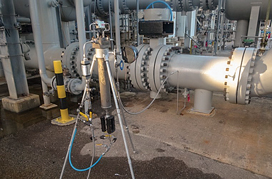
Feed gas contamination testing was performed in connection with liquids carryover in the gas stream. This testing was carried out at varying gas feedrates to see how it affected carryover quantities. Samples of the liquids in the gas stream were collected using a test system. Fig. 5 shows the assembled gas coalescer testing system connected to a slipstream of the inlet gas to the amine unit. Another unit was connected to the amine unit contactor outlet to quantify amine carryover.
 |
|
FIG. 5. Gas coalescer testing system upstream of the amine unit contactor. |
The testing system consists of a high-pressure housing that contains the high-efficiency coalescer element. A metered slipstream of gas flow is routed from the high-pressure feedpoint of the main stream into the testing system. Solids and liquids are separated, and the gas flow is sent to a low-pressure point in the main stream. The testing device has a number of components to measure flow, temperature, pressure, differential pressure and liquid buildup levels.
Testing is performed continuously over the course of at least 48 hr to account for process variability and environmental factors, and to produce more accurate results. Flow calculations are carried out carefully to compensate for different gases and accurately extrapolate contamination loadings from the test systems to the main gas flow. Testing is performed in an isobaric mode and can also be performed in an isokinetic mode. At the bottom of the test system is a site glass with an inner reservoir to accommodate the drained liquids. The site glass is calibrated to measure liquids accumulation. Liquids can be removed from the system through a drain valve. The separated liquids can then be analyzed for their composition and concentration, and a better understanding of process challenges can be gained.
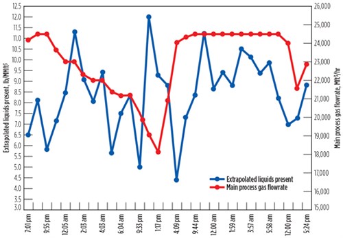
Fig. 6 shows the amine solvent carryover rates from the test system, extrapolated to the full gas flowrate of the plant. As gas was processed and the gas feedrate to the amine unit was varied, the test system continuously removed liquids from the slipstream. The volume of liquids removed over time was recorded approximately every hr, and the amount removed each hr was extrapolated to determine the amount of carryover in the gas stream in that time period. It can be seen that, as the plant gas flowrates dropped, the level of carryover also declined; conversely, as the gas flow increased, the carryover also increased. This correlation seemed to be directly associated with the entrance of contaminants into the plant.
 |
|
FIG. 6. Extrapolated liquids carryover from gas coalescer testing system data. |
Further testing was performed on the liquid samples collected, using a testing unit equipped with a water wash at the inlet. Several water samples were analyzed for foaming. Foaming episodes at the amine unit contactor were thought to be caused by water-soluble surfactants scrubbed with the water wash. The amine unit contactor therefore operated in a manner conducive to foaming and amine carryover.
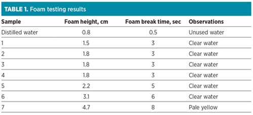
Table 1 shows the foam tests performed using a glass cylinder fitted with a porous glass frit and an air flow of 1 l/min. All samples produced higher foam height and slower break time compared to water. All seven samples of scrubbed water were taken, as water was recirculated in the test unit to remove gas-phase components. The results suggested that surfactants in the inlet gas caused amine solvent to foam. In addition, the amine unit contactor was operating in a “spray mode” caused by small liquid height on the trays due to under-circulation.
 |
Case 2: Feed contamination testing, solids removal and H2S scavengers. A natural gas processing facility with two amine units (Plant 1 and Plant 2) was experiencing problems with chemical poisoning and fouling in the feed gas stream at the amine unit train at Plant 2. Foaming episodes were also observed in the regenerator tower. It was suspected that a greater distribution of contamination was sent to Plant 2 compared to Plant 1, with fouling and foaming challenges observed only in Plant 2. In fact, Plant 1 did not experience any foaming or fouling problems.
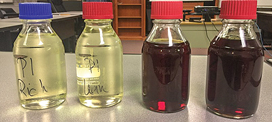
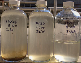
Samples of rich and lean amine solvent were taken from both Plant 1 and Plant 2, and visually inspected. Fig. 7 shows the samples for the amine solvents. Samples on the left are from Plant 1, and samples on the right are from Plant 2. Plant 1 samples showed a clear, pale yellow solution. No solids were observed, and no foaming tendency was found. Plant 2 amine solvent samples, however, showed a red color and produced stable foam.
 |
|
FIG. 7. Rich and lean amine solvents from Plant 1 (left) and Plant 2 (right). |
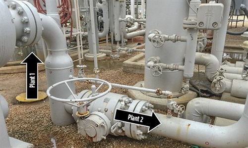
Fig. 8 shows the point where the feed gas is split between Plant 1 and Plant 2. The feed gas comes from underground and exits as the gas is split into a tee. The feed gas traveling up the pipe goes to Plant 1, and the side arm feeds into Plant 2. It might seem intuitive that, by inertia, the contaminants would travel straight up the pipe into Plant 1. However, this is not the case, and it appears that most contaminants take the path of the side stream.
 |
|
FIG. 8. Inlet piping to facility where feed gas flow is split between Plant 1 and Plant 2. |
One test unit was connected to the inlet of the coalescer, and another was connected to the outlet. Both units were operated simultaneously to capture, in real time, what was entering and exiting the vessel. The only time liquids were observed was in the inlet unit, which was due to a pig launched earlier that morning. Fig. 9 shows the liquids captured. To isolate solids from the inlet feed gas, a high-pressure membrane holder with a 0.7-micron glass fiber membrane was operated with a slipstream of the feed gas in parallel to the gas/liquid separator. The isolated solids were retained for analysis to identify the nature of the contamination.
 |
|
FIG. 9. Liquids captured in the inlet test unit after pigging pipeline. |
Inspection of the coalescer vessel and elements showed a distinctive solid that was off-white in color and had a foul odor. A total of 65 process additives were screened for solids formation and foaming when contacted with the amine solvent. More than 50% of the additives showed chemical incompatibility effects with the amine solvent in terms of solids formation leading to fouling and/or foaming.
Water injection to the feed gas at the inlet and outlet unit was performed. The purpose of the water injection is to scrub the gas of any water-soluble contaminants. The water is injected into the process with a high-pressure pump and is aerosolized through an atomizing nozzle. The water injected is filtered and recycled back through the unit. Recycling the water allows for any contaminants that are scrubbed to build to a measurable concentration so that any analysis or testing, such as surface tension or foam testing, can have detectable results.
The injection water from the units installed upstream and downstream of the inlet gas coalescer showed foaming tendencies during foam testing and surface rheology analysis. This foam formation is an indication that water-extractable contaminants that cause amine foaming were traveling across the coalescer and reaching the amine solvent into the contactor. It was then discovered that the plant has a water injection system in place upstream of the coalescer, but it was operating at a very low injection rate.
A recommendation was made that the water injection rate be increased to scrub out any water-soluble contaminants and remove the water at the inlet coalescer. This recommendation was followed, and a decrease in foaming episodes was observed.
A recommendation was also made that a prefilter be installed upstream of the coalescer to handle the solids contamination that was observed during testing. This recommendation is in the process of being implemented. The testing also showed that minimal liquids contamination was present in the feed gas, except during pigging events; even during such events, the inlet coalescer proved capable of handling the liquids ingress.
Case 3: Gas plant amine foaming and corrosion inhibitors. A gas processing plant was experiencing amine foaming intermittently. This affected the flow into the amine unit by 50%. Treating was mainly for CO2. As foaming occurred, the level in the contactor bottom was lost and differential pressure in the contactor increased. The amine solvent (lean and rich) had a transparent, pale yellow color, with no indication of unusual contaminants.
Onsite testing for foam formation and origins determined that the new amine from storage had a foaming tendency. This is unusual, and further testing revealed that the amine from storage had high sodium content. It was postulated that the truck carrying the new amine solvent into the plant had traces of a sodium-based surfactant, such as sodium dodecyl sulfate; however, that theory was never confirmed.
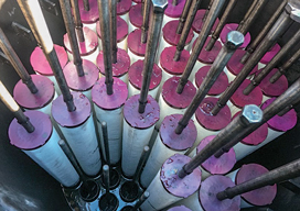
Inspection of the inlet gas coalescer to determine if liquid bypass was occurring was very revealing. Fig. 10 shows the interior of the inlet gas coalescer vessel, where a series of problems was detected. The top of the coalescer elements at the red endcaps showed liquid accumulation. These endcaps are actually liquid bypass, as the elements were not completely sealed to the incoming flow. The flow direction is from inside to outside; therefore, the liquids were forced from the interior of the coalescing element into the upper endcaps. This is a common mistake in coalescer vessels.
 |
|
FIG. 10. Gas coalescer vessel interior showing the coalescer elements, with some elements removed. |
The coalescing elements were not placed into the vessel by using a radially homogenous pattern. It appeared that the elements might have been maximized into the vessel in a linear pattern. Elements were touching each other, and the small or nonexistent space between the elements caused high annular gas flow, which led to liquid carryover into the gas outlet.
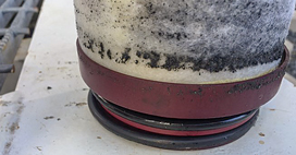
Inspection of a spent coalescer element that was removed from the gas coalescer vessel was also very revealing with regard to how the system operated. Fig. 11 shows the interior bottom of the coalescer element. The line of solids indicated the liquid level to which the elements were exposed. This line indicated that the elements were flooded in the bottom section, preventing proper liquid drainage. Closer inspection of the instrumentation in the vessel showed that the port was incorrectly placed and that the lower-level sensor was higher than that required for proper liquid drainage.
 |
|
FIG. 11. Bottom section of used gas coalescer element. |
Testing of the inlet gas was performed using one testing unit connected to a slipstream to the inlet feed gas. Fig. 12 shows the testing unit and the sampling point. The testing unit removed some liquids by coalescing, and these liquids produced foaming when added to an amine solvent. However, water scrubbing of the feed gas and testing of the scrubbing water showed considerable foam formation on its own and when added to unused amine solvent. Table 2 shows the foaming tests performed using a glass cylinder fitted with a porous glass frit and an airflow of 1 l/min.
 |
|
FIG. 12. Testing unit for sampling of feed gas upstream of the amine unit contactor. |
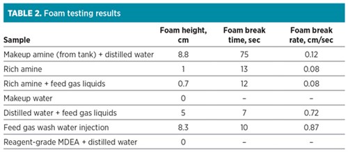 |
Table 2 shows that makeup amine from storage caused significant foaming. The rich amine did not foam significantly, but the addition of feed gas liquids did cause foaming. The makeup water did not show foaming and was eliminated as a source of contamination. Wash water from the injection recirculated in the feed gas also showed foaming, which suggests that the feed gas contains water-soluble contaminants that contribute to the foaming issue. Fig. 13 shows the foam testing setup in operation.
 |
|
FIG. 13. Foaming tests using a glass cylinder fitted with a porous glass frit and an airflow of 1 l/min. |
To determine the nature of the contaminant in the amine unit causing foaming, an analysis was performed of an extracted solvent (methylene chloride) sample of the amine carryover when foaming was taking place and amine was spilled into the knockout drum. The results of the Fourier-transform infrared (FTIR) analysis for the sample are presented in Fig. 14. Peaks of interest in the spectrum are listed in Table 3 along with the frequency, functionality and vibrational motion, in addition to peak shape and intensity.
 |
|
FIG. 14. FTIR analysis of an extracted sample of amine carryover. |
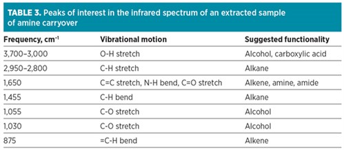 |
The spectrum for the sample showed predominantly alkane and alcohol functionalities, with some carboxylic acid structures and possible amine groups. The precise identity of the contaminant could not be accurately determined; however, this contaminant was not originally part of the previously sampled and analyzed feed gas. This component should also not be part of the normal MDEA-based amine solvents. This product could be degraded amine, oxidized amine or a foreign chemical present in the inlet gas from process additives.
Finally, whether or not the contaminant extracted from the amine solvent component played a central role in foaming is unclear. However, foaming tests conducted by contaminating clean 50% MDEA/distilled water with this material did generate significant foam column height and foam stability.
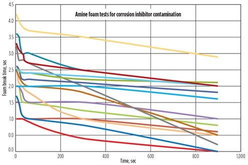
Production corrosion inhibitors and MDEA solvent foaming. A series of production chemicals was evaluated to determine if upstream process additives can cause amine foaming when they ingress into amine units. Corrosion inhibitors used by a gas producer were tested for their effect on MDEA amine foaming. The tests were performed by taking 20 ml of 50% laboratory-grade MDEA diluted in distilled water and adding the individual corrosion inhibitor (0.1 ml). A total of 14 different production corrosion inhibitors were tested.
Fig. 15 shows the results of the foam tests. The red line represents the control sample with no corrosion inhibitor. All 14 corrosion inhibitors produced foaming in the amine solvent. In fact, most formed a stable foam that was persistent for more than 1 hr. These results show that upstream process additives, such as corrosion inhibitors, can cause complex amine foaming situations. In some cases, they can be quite severe. These components should not be used upstream of amine units if possible. Alternatively, they should be removed from the feed gas prior to the amine unit by using a water wash.
 |
|
FIG. 15. Foaming tests of laboratory-grade 50% MDEA in distilled water with added corrosion inhibitors. Each line represents a different corrosion inhibitor used in oil and gas production operations; the red line represents the control sample containing no corrosion inhibitor. |
Takeaway. Foaming caused by surfactants is perhaps one of the most complex problems facing amine units in terms of foaming upsets and foam mitigation. Surfactants can be present in the feed gas in the water, hydrocarbon and gas phases. Removal of surfactants at the source is the best strategy for elimination. Once the surfactant is present in the amine solvent, limited avenues exist for its removal. In some cases, antifoams are not effective in removing foam.
In addition, activated carbon can also be ineffective in removing upstream production chemicals, such as corrosion inhibitors that are also surfactants. Water wash can be an effective strategy to remove surfactants from the feed gas. Amine foaming invariably will cause amine losses. In plants not using proper antifoams, gas feedrates might need to be reduced for controlling foam.
Inlet gas testing using a slipstream and water scrubbing is one of the most effective ways to determine if surfactant contaminants are present in the feed gas. Foaming tests are also instrumental in determining the effect of surfactants in foaming tendency and foam stability. GP
 |
David Engel has more than 25 yr of industrial experience in a variety of chemical engineering and chemistry areas. He is the inventor in 22 US patents and the author of a number of technical and scientific papers. Dr. Engel has developed business and technology for Eastman Kodak, Eli Lilly, Pentair, General Electric and Sulphur Experts worldwide. He has specialized in chemical engineering, process chemistry, optimization and contaminant removal technologies. Dr. Engel is the Managing Director of Nexo Solutions and the Technology Leader for Exion Systems. He holds a BS degree in industrial chemistry, an MS degree in chemistry and a PhD in organic chemistry. He is also Six Sigma and Project Management certified. Dr. Engel is President of the American Filtration Society, Southwest Region; and a member of the Gas Processors Association Technical Section M, as well as a member of the boards of directors at several companies.
 |
Heath Burns is a Senior Engineer and Systems Specialist with Nexo Solutions, and an Engineering Leader for Exion Systems. He holds a BS degree in mechanical engineering technology from Texas A&M University.
 |
Scott Williams is a Staff Process Engineer at Nexo Solutions. He holds a BS degree in chemical and biological engineering from the University of Colorado in Boulder, Colorado.


Comments