
Proper regeneration of molecular sieves in TSA processes—Part 1
The regeneration of molecular sieves is the most crucial step in temperature swing adsorption (TSA) processes. It determines the performance and operating cost of molecular sieves over a given lifetime. It is well known that molecular sieves age with each regeneration cycle. The adsorption process on the molecular sieve is a complex phenomenon and often poses challenges for the design and operation of the units, due to a number of parameters that govern the efficiency of such processes.
Poor design decisions and deviations from design conditions can cause a wide range of operating issues in a molecular sieve unit. Most of the damage from these upsets or deviations from design conditions usually occurs during the regeneration step. If not addressed properly, these upsets can result in reduced lifetimes, increased pressure drops across beds, loss of product quality, formation of hydrates, increased system corrosion or increased plant downtime—all of which have cost implications. It is, therefore, important to properly design and operate the regeneration phase of molecular sieves.
The main design principles and recommendations for the regeneration step in TSA processes are presented here, along with ways to address key issues concerning troubleshooting, optimizing and adapting plant operations under different constraints. Part 1 focuses on the general design philosophy and key operating parameters, and Part 2 will concentrate on the regeneration gas and contaminants.
Industrial adsorption on zeolite molecular sieves. The principles of industrial adsorption on the zeolite molecular sieve have been well documented in the academic and industrial worlds.1–8 Zeolites are crystalline aluminosilicates with a uniform pore size that are extensively used in adsorption applications. They are made of a three-dimensional succession of SiO4 and AlO4 tetrahedra (sodalite cages) in the presence of metal ions to balance the negative charges created by the trivalency of aluminum. This results in a final network of repeated crystals with channels and uniform size cavities (known as porosity) that exhibit a large and electronically active surface area.
In the separation application, for an impurity to be efficiently adsorbed, the molecule of the impurity should be polar and of an appropriate size that corresponds to the pores present in a given type of zeolite. Two types of zeolites are widely used for separation: zeolite A (“LTA” crystal structure) and zeolite X (“FAU” crystal structure). The diameters of the pores and cavities depend on the type of zeolite and on the nature and size of the charge-compensating cations, which are situated around the pores.
The 4A and 13X are basic forms of zeolite based on Na+, but with two different crystal structures (types A and X, respectively). In a type A zeolite, if Na+ is partially replaced by K+, which has a larger ionic radius, the result is a smaller pore opening of 3 angstrom, or Å (i.e., “3A” zeolite). When Ca2+ replaces two Na+, the result is a bigger pore opening of 5 Å (“5A” zeolite). Zeolite X pores, in the Na+ form, are of size 7.4 Å.
The zeolite crystals are compounded with a binding clay to form beads or extrudates. Zeolites, also known as molecular sieves, are used industrially in the fixed beds to purify a gas or a liquid stream. Depending on the application and molecules to be captured, an appropriate type of zeolite is chosen. The adsorption capacity of a molecular sieve is governed by isotherms (function of temperature and pressure), and once the molecular sieve is saturated with impurity molecules, the equilibrium conditions need to be changed (either temperature or pressure or both) to desorb the impurity and reuse the molecular sieve for adsorption. This phase is called the “regeneration” of a molecular sieve.
Adsorption with molecular sieves is usually performed in systems having at least two vertical absorbers, one in adsorption and one in regeneration. For high flowrates, several adsorbers can be used in parallel, as shown in Fig. 1, and up to two in regeneration. The regeneration stage features cooling and heating in series, for the case where the regeneration gas flowrate must be reduced.
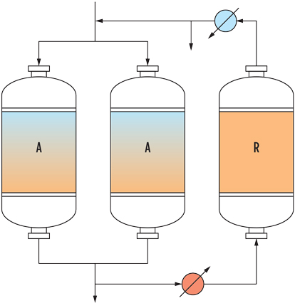 |
| FIG. 1. Example of a “2+1” system with two vessels in adsorption in parallel and one in regeneration with dry product. |
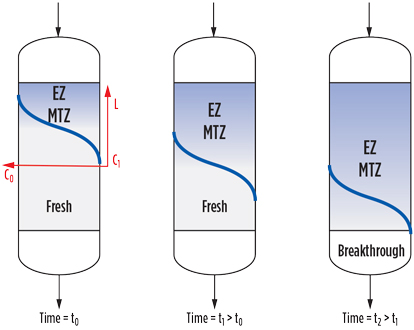
During adsorption, a molecular sieve bed is modeled by a three-zone system, as illustrated in Fig. 2. Close to the inlet is the equilibrium zone (EZ), where the adsorbent is in equilibrium with the process fluid—i.e., saturated with impurity at the partial pressure and temperature conditions.
 |
|
FIG. 2. Equilibrium zone, mass transfer zone and fresh zone. |
The EZ is followed by the mass transfer zone (MTZ), where the dynamics of adsorption take place. The MTZ shows a gradient of the impurity concentration, which decreases to a required outlet specification and can be defined as the length required for the adsorbent to bring the impurities from their initial concentration to the final specification.
The third area is made of fresh adsorbent that, for a given adsorption time, has not been in contact with the impurities.
Sieve design. A number of parameters influence the design and operation of a molecular sieve unit. The operating temperature and partial pressure of an impurity, along with the type of molecular sieve (3A, 4A, 5A, 13X) defines the adsorption capacity of that impurity. Flowrate and pressure drop constraints, coupled with the adsorption capacity, are important to select the appropriate flow regime, mass transfer kinetics and, by extension, the design of vessels.
An adapted pore size of molecular sieve, along with an appropriate bed configuration (based on adsorbent size and composed of big particles, small particles or a split bed), also influence the size of vessels. The choice of an appropriate diameter-to-height ratio will influence the pressure drop and flow distribution, as well as the regeneration duty requirement.
Regeneration of molecular sieves is normally performed in either the pressure swing adsorption (PSA) processes or in the TSA processes. In the first case, the change in the adsorption equilibrium is obtained by decreasing the pressure. PSA processes, which are usually used in non-aggressive applications with less stringent outlet specifications (i.e., 100 ppm or more), are less sensitive to process deviations during operation and usually give long lifetimes.
In the second case, the change in the adsorption equilibrium is obtained by increasing the temperature with the help of a hot gas (180°C–300°C). TSA processes, usually used in applications with stringent outlet specifications (0.1 ppm–1 ppm), are more sensitive to process deviations during operation.
A majority of natural gas, petrochemical and refinery units are TSA based. The design for these units is provided by molecular sieve suppliers specializing in the know-how of these applications. The PSA process is usually designed by technology licensors, and the molecular sieve supplier role provides appropriate product and as-needed operational assistance, so that a unit is less susceptible to deviations or problems. TSA-based regeneration processes are discussed here.
Regeneration phase design. It is well known that molecular sieves age over time and with each regeneration cycle. The speed and the way the sieves age determine the lifetime of a unit. Therefore, it is important to properly design and operate the regeneration phase. An incorrect pressure change rate can lead to sub-zero temperatures, resulting in ice formation that will damage molecular sieve structure. Channeling or lifting of the bed can occur if an appropriate pressure drop per length is not respected.
The heating step during regeneration is critical for several reasons: The gas must be clean enough to avoid side effects (which are usually exacerbated at high temperature), and it must carefully address the required regeneration energy duty (i.e., temperature, flowrate, duration) requirement. Correct temperature ramps should be provided to avoid damage of the molecular sieves by thermal stress.
An intermediate heating step is often recommended in the drying applications to avoid the phenomenon of hydrothermal damaging of the molecular sieve. An appropriate temperature profile that is adapted to the specific type of molecular sieve should be provided, along with sufficient heating time, to attain a stable outlet temperature plateau to mark the completion of regeneration. The type of regeneration gas (e.g., contaminants content and physical properties), flowrate and flow directions are equally important for efficient regeneration. After heating, a cooling phase is needed before switching back to adsorption; this helps avoid a temperature peak that might disturb the downstream process.
A wide range of operating issues in the molecular sieve units can be caused by poor design decisions, as well as deviations from the design conditions like change of process conditions, presence of contaminants,2,9 emergency shutdowns, etc. A major part of the damage from these upsets usually happens during the regeneration step at high temperatures. If not addressed properly, these upsets can result in reduced lifetime, increased pressure drop across beds, loss of product quality, hydrate formation, increased system corrosion or increased plant downtime—all of which have cost implications. Therefore, it is important to properly design and operate the regeneration phase.
Over the course of this two-part article, recommendations for the design of the regeneration step in TSA processes will be presented, along with how these recommendations can be adapted for several key issues that industrial operators may face while operating a molecular sieves unit, and which EPC companies may face when designing a new unit.
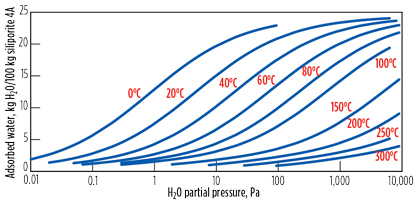
Regeneration of molecular sieve. The equilibrium adsorption capacity of an impurity on a given molecular sieve is determined by using isotherms. As an example, Fig. 3 illustrates the isotherms that give the equilibrium adsorption capacity of water on a 4A molecular sieve as functions of temperature and partial pressure of water. At the end of the adsorption phase, the molecular sieve is saturated and no more impurity can be adsorbed.
 |
|
FIG. 3. Water adsorption isotherms for 4A molecular sieves. |
However, the adsorption is reversible. The adsorbed impurity can be desorbed and eliminated from the molecular sieve by shifting the adsorption equilibrium and modifying the operating conditions—or, more commonly, by increasing the temperature, by decreasing the pressure, or by doing both. At the end of regeneration, the molecular sieve can recover most of its original adsorption capacity—i.e., it is “regenerated.”
Thermal regeneration is a widely used method in the oil and gas industry. To regenerate the molecular sieve, several steps are generally involved:
- Depressurization
- Draining (in liquid application only)
- Purge
- Heating (temperature ramp-ups; intermediate heating step, if applicable; main heating step)
- Cooling
- Repressurization
- Standby.
The regeneration stage often starts with a depressurization step. The depressurization is required if the regeneration is performed at a pressure lower than that of the adsorption phase. This may arise for different reasons, as the regeneration gas is not the product gas, but rather another gas available at a lower pressure, such as N2, H2, CH4 and fuel gas. The lower pressure can also be chosen to optimize the regeneration energy requirement.
In liquid applications, the depressurization step can be followed by a draining step. During the draining step, all liquid must be evacuated from the adsorber before the introduction of a heating gas. The liquid is generally drained by gravity flow. At the end of the draining step, almost all of the liquid is drained, except for a very small portion that is trapped in the molecular sieve and on the surface of the adsorber vessel. This liquid is removed during the purging step, where cold regeneration gas is introduced for 1 hr–2 hr to strip off this remaining liquid.
Following this step, the heating step is started by introducing hot regeneration gas into the vessel. The temperature is slowly increased to the heating temperature to avoid thermal stress. The energy needed to obtain suitable regeneration is achieved through the sum of four components:
- Energy needed to heat the molecular sieve bed to its desired temperature:
Q1 = m1 × Cp1 (T2 – T1) - Energy needed to heat the adsorber:
Q2 = m2 × Cp2 × k (T2 – T1) (Note: Depends on whether the insulation is external or internal) - Energy needed to heat and desorb the adsorbate mass retained in the bed: Q3 = m3 × L
- Energy losses.
In this summary, the following definitions are used:
m1 = Mass of the molecular sieve to be heated
m2 = Mass of the steel to be heated
m3 = Mass of the total water (or other impurity) adsorbed during adsorption phase
Cp1 = Heating capacity of the molecular sieve
Cp2 = Heating capacity of the steel
k = Correction factor that depends on whether the insulation is internal or external
T1 = Initial bed temperature
T2 = Final bed temperature
L = Enthalpy of desorption of the impurity.
A hot gas with a certain flowrate, a specific temperature and a given flow time supplies the heating energy necessary for the regeneration.
As can be seen from the isotherms, the temperature rise causes a decrease of the impurity loading on the molecular sieve. Passing a hot gas stream has two effects: first, desorption of the impurity due to the temperature rise, and second, transport of the desorbed impurity out of the bed. This means that a certain quantity of heat at a minimum temperature should be brought into the adsorber to desorb the impurity.
Furthermore, if the regeneration gas flowrate (or duration) is too small, then an accumulation will occur on the top layers of the molecular sieves due to a lack of desorption energy. In the case of laminar flow or channeling, the gas does not pass through the entire bed due to the preferential path of the flow, but rather through only part of the bed. This may lead to localized accumulation in the bed.
At the end of the heating step, the molecular sieve is regenerated. However, the impurities are not completely desorbed. A certain residual content of impurity always remains in the molecular sieve, corresponding to the equilibrium conditions at the end of heating and the thermal profile observed by the molecular sieve.
For example, a new sieve is activated at 500°C–600°C at the end of a manufacturing process and has very low residual water content (< 0.5%). The value of this residual impurity content depends on the quality of regeneration (i.e., temperature, time, flowrate and other process parameters) and the age of the molecular sieve. The result is a reduced adsorption time for the next adsorption cycle.
Molecular sieve suppliers often design the unit based on the end of lifetime adsorption time. This means that, initially, the adsorption time (and, therefore, the adsorption capacity) of the molecular sieve is higher when the molecular sieve is fresh. Throughout its lifetime, this adsorption time decreases due to aging. These factors mean that the molecular sieve unit can be operated in two ways:
- Some units are operated on a “fixed” cycle time—i.e., the cycles always have the same duration. At the beginning of the lifetime, when the adsorbent is new, there is still fresh, unused molecular sieve in the vessel. For these units, the design is optimized when, at the end of the last adsorption phase of the foreseen product lifetime, the third zone (fresh sieve) is close to zero and the MTZ nearly reaches the limit of the bed.
- Other units are operated under “breakthrough” conditions—i.e., the end of the adsorption time is defined when impurities are detected at the outlet of the bed. In that case, the adsorption time decreases slowly throughout the product lifetime.
After heating, a cooling phase is needed before switching back to the adsorption; this helps avoid a temperature peak that would usually cause significant disturbance to the downstream process. The energy needed to obtain suitable cooling is the sum of three components:
- Energy needed to cool the molecular sieve bed to its desired temperature:
Q1 = m1 × Cp1 (T5 – T4) - Energy needed to cool the adsorber:
Q2 = m2 Cp2 k (T5 – T4) (Note: Depends on whether the insulation is external or internal) - Energy losses.
In this summary, the following definitions are used:
m1 = Mass of the molecular sieve to be cooled
m2 = Mass of the steel to be cooled
Cp1 = Heating capacity of the molecular sieve
Cp2 = Heating capacity of the steel
k = Correction factor that depends on whether the insulation is internal or external
T5 = Initial bed temperature
T4 = Final bed temperature.
A cool gas with a certain flowrate, a specific temperature and a given flow time supplies the energy necessary for cooling.
At the end of the cooling step, the vessel is repressurized to the adsorption pressure, and also refilled with liquid in case of liquid applications, and then put on standby before switching to the adsorption phase of the next cycle.
he major parameters involved in the design of regeneration are depressurization/repressurization rates, heating temperature, heating time, temperature ramp-ups, cooling time, regeneration gas flowrate, regeneration gas type (composition, temperature and pressure) and flow direction, and the presence of poisons or deviations. The standard recommendations for several of these parameters, and how they can be adapted in the case of process deviations, will be presented in Part 2.
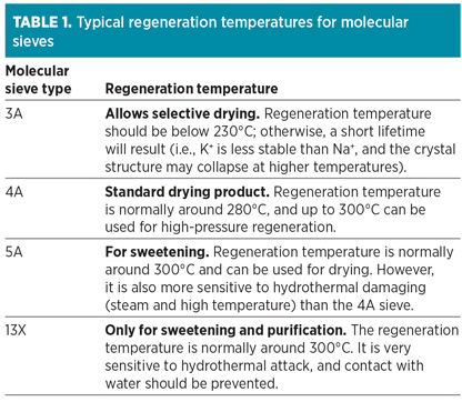
Temperature and time. The standard regeneration temperature usually depends on the type of molecular sieve used. This temperature can be further adjusted depending on the particular application and, in some cases, where poisons or process deviations are present.
The typical molecular sieve types used in the oil and gas industry are 3A, 4A, 5A and 13X. The standard regeneration temperatures for these molecular sieves are outlined in Table 1.
 |
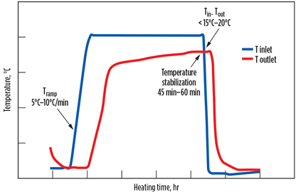
A typical regeneration temperature profile is illustrated in Fig. 4. The heating temperature is slowly increased through the application of a heating ramp-up step. Once the heating temperature is reached, it is maintained for a few hours to gradually desorb the impurity. The heating is completed when a plateau is reached at the outlet temperature for approximately 45 min–60 min when the temperature either increases very slowly or remains constant, depending on vessel size.
 |
|
FIG. 4. Typical regeneration temperature profile. |
The heating is efficient if, at the end of the process, the difference between the inlet and outlet temperatures is less than 15°C–20°C, depending on the quality of vessel insulation. At this point, only the heat losses through the wall make the temperature difference, but no more impurities are desorbed.
The time allocated for the different regeneration steps is another important parameter for efficient regeneration. The heating time and cooling time are calculated based on duty requirement and the temperature and flowrate of the regeneration gas. The heating time should be a minimum of 2 hr; below this value, the regeneration is often incomplete, as the molecular sieve bed is not fully heated to the regeneration temperature.
As previously stated, the outlet temperature stabilization (45 min–60 min) is a good sign that the regeneration is completed. The heating ramp-up is typically 5°C/min–10°C/min. Beyond 10°C/min, if the heating is too fast, it can result in thermal stress in the molecular sieve—or, in drying applications, it may lead to retrocondensation (to be discussed in Part 2), resulting in quick aging of the molecular sieve.
In some cases where an intermediate heating step at 120°C is applied to prevent retrocondensation, a minimum of 30 min should be allocated to this step. The depressurization/pressurization rate should be 1 bar/min–3 bar/min, and should not exceed 3 bar/min. In liquid applications, where draining and refilling is required, the typical time allocated for these steps is 1 hr–2 hr. These steps are followed by a cold purge step (i.e., cold regeneration gas purging to remove trapped liquid), usually for around 1 hr.
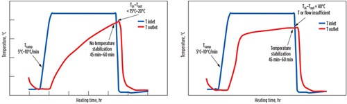
Fig. 5 illustrates two bad examples of the regeneration temperature profiles to be avoided. On the left side, a temperature stabilization is not reached for about 45 min–60 min, meaning that the regeneration is not complete. The outlet temperature should stabilize at 15°C–20°C under the inlet temperature. Here, the water is only partially removed and accumulates throughout the cycles, leading to a reduced working capacity and to early breakthrough.
 |
|
FIG. 5. Examples of inefficient regeneration temperature profile. |
On the right side of Fig. 5, even though a temperature stabilization appears to have been reached, the difference between inlet and outlet temperature is approximately 40°C. At such a level of difference, the regeneration is not complete. This difference is frequently due to an inefficient insulation leading to high wall losses. It can also be due to severe channeling (e.g., arising due to the presence of aggregates) that may reduce efficiency of heating by the regeneration gas.
In some cases, the heating duty supplied is at an insufficient level (either flowrate or time), leading to a very slow increase in temperature at the end. The result of this considerable difference between the inlet and the outlet temperatures is a high amount of residual water in the molecular sieve bed at the end of the regeneration. Both cases can impact the performance and the lifetime of the molecular sieve. For such cases, regeneration time, regeneration temperature and/or regeneration gas flowrate should be increased.
For the cooling step, a temperature ramp-down is not required. If the duration of cooling is too short, the result will be a temperature peak of the gas during adsorption after switching from regeneration to adsorption. This may impact the downstream process. For the cooling, low flowrate (laminar flow) can also lead to a horizontal temperature gradient (higher temperature at the wall, lower temperature in the middle), resulting in a temperature peak during the adsorption phase. Sufficient cooling time and flowrate should be allocated to prevent this phenomenon.
Retrocondensation. In applications such as natural gas drying, cracked gas drying and olefins drying, retrocondensation is a recurring operational issue that happens during the regeneration phase, leading to hydrothermal damaging of the molecular sieve. This phenomenon is well known and is widely discussed in the literature.2,8,10,11
By heating too fast at a high temperature, water rapidly desorbs from the lower layers, while the bed experiences an important temperature gradient—i.e., its bottom is already hot, but its upper section is still at the adsorption temperature. When reaching these colder parts of the bed, the regeneration gas gets oversaturated, and water “retrocondenses” on the top layers, especially near the vessel wall.
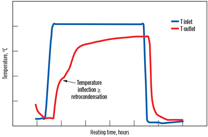
This phenomenon can be seen on the outlet temperature curve of the regeneration gas that shows an inflexion (typical of a change of physical state), as illustrated in Fig. 6. As the temperature increases, it results in boiling water in the molecular sieve bed. This phenomenon is enhanced at high pressures and low regeneration flowrates. The consequence of water condensation is the weakening of both the binder and the zeolite structure. The binding clay is leached from the molecular sieve structure and disaggregates to powder. Eventually, it also rearranges to form agglomerates around the vessel.
 |
|
Fig. 6. Temperature inflection indicating retrocondensation. |
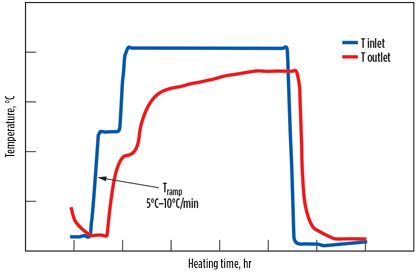
Hydrothermal damaging can be significantly reduced, and sometimes stopped, by performing a suitable heating and regeneration procedure. A heating ramp-up of a few degrees per minute, together with a preliminary heating step of 30 min to 1 hr at 100°C–120°C is the most effective solution, as illustrated in Fig. 7.
 |
|
Fig. 7. Intermediate heating step applied in a typical regeneration temperature profile to avoid retrocondensation. |
The benefit of a gentle heating step is to control water desorption while delivering a more even movement of initial heat through the bed. This scenario is preferable to a situation where the hot, saturated gas arrives at the colder parts of the vessel to condense.
Another good practice may be to increase the regeneration gas flowrate to strip more water out of the bed and heat the upper section faster, or to lower the regeneration pressure.
Pressure. Like temperature and time, pressure is another important parameter for the design of the regeneration phase. The lower the pressure, the easier it is to desorb, as is evident from adsorption isotherms. The regeneration phase pressure can be the same as that of the adsorption phase (if product or inlet gas is used as regeneration gas) or different from the adsorption phase pressure (if another gas, which can be supplied at a different pressure, is used for regeneration). Furthermore, it is important to note that a larger flowrate of regeneration gas is needed if the regeneration pressure is high.
Two operating scenarios can be present, depending on the pressure range:
- Low pressure—heating limited: The regeneration gas must bring in the energy for heating and desorption (i.e., the boiling temperature of water at the regeneration pressure is below the regeneration temperature, so there is no limitation for evaporation)
- High pressure—stripping limited: The regeneration gas must strip off (push out) the desorbed water, in addition to bringing in the energy for heating and desorption.
The limit between both scenarios is approximately 30 bar–35 bar. For instance, a regeneration at 60 bar may require up to 25% more regeneration gas quantity. A correction factor is often applied, depending on the regeneration pressure to the gas flowrate.
The pressure drop across the molecular sieve bed depends on the flowrate, viscosity, density, packing, size and shape of the molecular sieve. The start-of-life pressure drop is usually calculated using the Ergun equation. The pressure drop across the bed increases over the lifetime, and its evolution depends on how the unit is operated and whether any process deviations (e.g., liquid carryover, retrocondensation, coking or other type of damage) occurs on the molecular sieve. Under standard conditions, as a rule of thumb, the end-of-life pressure drop is usually double the pressure drop at the start of life.
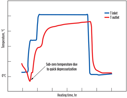
In cases where the regeneration phase and adsorption phase pressures are different, depressurization and repressurization steps are required in the beginning and at the end of regeneration, respectively. The pressure change rate is very crucial and should be between 1 bar/min and a maximum of 3 bar/min. A high depressurization rate can result in a sudden temperature decrease and sometimes sub-zero temperatures (temperature well), as illustrated in Fig. 8. At this temperature, the water present in the molecular sieve can form ice. As the volume of ice is greater than the volume of water, this can potentially damage the molecular sieve. Furthermore, when the heating starts, ice vaporizes and damages the crystal structure when leaving, creating dust and breakage.
 |
|
Fig. 8. Sub-zero temperature due to high depressurization rate. |
The temperature decrease can be explained by two phenomena. In some cases, the Joule–Thomson effect12,13 may provide an explanation. For a given pressure, a gas has an inversion temperature. If the gas is initially above this temperature, then the temperature will further increase if the pressure decreases, and vice versa:
- If Tinitial > Tinversion, then a decrease in pressure will result in an increase in temperature
- If Tinitial < Tinversion, then a decrease in pressure will result in a decrease in temperature.
The extent of the Joule–Thomson effect depends on the type of gas. Normally, this phenomenon is uncommon in natural gas, but common in cracked gas applications. In some cases, the phenomenon of liquids evaporation (at a given T and P) and desorption (endothermic) can also lead to a decrease in temperature.
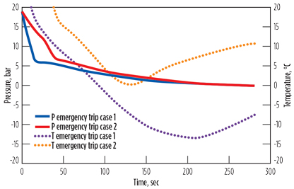
Fig. 9 demonstrates an example from propane drying, where sub-zero temperature may occur during trips. In the first case, the initial pressure drop from 19 bar to 6 bar was too fast and resulted in a temperature decrease to –15°C. In the second case, the pressure change rate was decreased, and a sub-zero temperature was avoided.
 |
|
Fig. 9. Sub-zero temperature during emergency trip. |
Part 2. In Part 2, the type of regeneration gas and flow and the presence of olefins, oxygen, methanol, hydrocarbon retrograde condensation, carbonyl sulfide formation and other contaminants will be discussed. GP
Literature cited
- Trent, R., “Dehydration with molecular sieves,” 51st Laurance Reid Gas Conditioning Conference, Norman, Oklahoma, February 2001.
- Terrigeol, A., “Molecular sieves contaminants: Effects, consequences and mitigation,” GPA Europe Annual Conference, Berlin, May 2012.
- Eguren, R. R., “Molecular sieves operational challenges,” 62nd Laurance Reid Gas Conditioning Conference, Norman, Oklahoma, February 2012.
- Meyer, P., “Molecular sieves troubleshooting,” GPA Europe Annual Conference, Lisbon, Portugal, September 2010.
- Keller, J. U. and R. Staudt, “Gas adsorption equilibria: Experimental methods and adsorptive isotherms,” Springer Science & Business Media, Berlin, Germany, 2005.
- Sun, L.-M. and F. Meunier, “Adsorption—Aspects théoriques—Techniques de l’ingénieur,” Génie des procédés, Vol. 1, J2730, March 10, 2003.
- Yang, R. T., Gas Separation by Adsorption Processes, Butterworth-Heinemann, Oxford, UK, 2013.
- Jain, S., T. Boucheres, L. Gomes and A. Ghoussoub, “Use of CFD modeling to optimize capital and operational costs of molecular sieve units,” GPA Europe Annual Conference, Athens, Greece, May 2016.
- Grace Davison, “Effects of contaminants on molecular sieves,” online: http://www.offenbar-energy.com/pdf/EFFECTS%20OF%20CONTAMINENTS.pdf
- Meyer, P. B. C., “Hydrothermal damaging of molecular sieves and how to prevent it,” GPA Europe, Paris, France, February 2003.
- Suckow, M., W. Lutz, J. Kornatowski, M. Rozwadowksi and M. Wark, “Calculation of the hydrothermal long-term stability of zeolites in gas-desulphurization and gas-drying processes,” Gas Separation & Purification, Vol. 6, No. 2, 1992.
- Zemansky, M. W., Heat and Thermodynamics, McGraw-Hill, New York, New York, 1968.
- Schroeder, D. V., Thermal Physics, Addison Wesley Longman, Boston, Massachusetts, 2000.


Comments