
Optimal design and operation of molecular sieves for gas dehydration—Part 2
Part 1 of this article examined the main design elements of a molecular sieve dehydration unit, although it is virtually impossible to design such a process unit without taking operational aspects into account. However, once a molecular sieve unit is constructed and the gas processing plant has started up, some elements during its operation require special attention.
Part 2 focuses on the operation of a molecular sieve unit used for natural gas dehydration. Debottlenecking and troubleshooting options are also discussed.
Addressing common issues. A contributing factor to molecular sieve deactivation is the deposition of liquids, such as amines, that originate from the upstream amine unit being deposited on the molecular sieve.1–6 Such liquids can enter the macropores of the molecular sieve and, during regeneration, cause severe degradation of the molecular sieve by destroying the binder material. This process can ultimately result in caking and coking, mechanisms discussed in Part 1.
The deposition of liquid droplets can arise from poor upstream liquid/vapor separation, retrograde condensation or a regeneration profile that results in the formation of liquid water. To minimize this effect, the knockout (KO) vessel upstream of the dryer beds usually has advanced deentrainment internals, such as vane type, mist mat, or swirl deck and mist mat (SDMM) installed. While these internals should provide adequate separation, it is conceivable that they have not been installed properly, which can lead to liquid carryover in the form of entrainment. It is also possible that a slug from the upstream amine unit will enter the molecular sieve bed. This type of liquid carryover is difficult to prevent and can cause serious damage to the molecular sieve unit, which usually requires immediate changeout unless it is identified early.
If operational indicators show that a large volume of liquid (e.g. through foaming of the upstream amine unit) has been deposited on the bed, then it can be mitigated only by a slow and careful ramp-up in the following regeneration step. Additional protection of the molecular sieve against small droplets can be provided by the installation of a guard layer on top of the bed. This layer is composed of a small coating of silica or alumina specifically installed to catch liquid droplets and protect the molecular sieve bed.
If capillary condensation of hydrocarbons takes place in the bed, this can also lead to a rapid increase in the rate of deactivation. Liquid hydrocarbons wet the sieve, covering it in a film, which adds extra resistance to the mass transfer of water molecules from the bulk gas phase to the molecular sieve active surface, reducing the water removal capacity of the sieve. Wetting of the molecular sieve also increases the sieve’s susceptibility to attrition, which will lead to dust formation, increased pressure drop and channeling. The only way to prevent these developments is to operate the molecular sieve beds a few degrees above the hydrocarbon dewpoint, which can be achieved by installing a heater downstream of the feed KO drum.
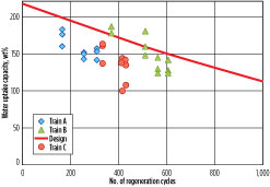
Capacity test runs, which provide information on the amount of water adsorbed by the molecular sieve at the time of testing, are essential for evaluating the performance of the molecular sieve over its run length and for estimating the remaining lifetime.3,7 Once the capacity has been determined from a test run, it can be plotted against the number of regeneration cycles that the bed has experienced. If the results of the test runs are plotted against the expected deactivation curve, then an evaluation can be made as to whether it is possible to reach the planned changeout time. When sufficient data points are collected over time, the true deactivation profile can be determined and extrapolated to estimate the remaining lifetime. The results of several of these test runs for three trains are summarized in Fig. 1.
 |
|
Fig. 1. Molecular sieve dehydration unit test run results. |
As shown in the graph in Fig. 1, the results suggest that the molecular sieve beds are deactivating much faster than expected. Once some certainty is established that the beds’ performance is indeed lower than expected, an attempt can be made to identify the cause. The aim is to avoid an unplanned shutdown for changing out the molecular sieves and to keep the units running until the planned shutdown. At that moment, only a limited amount of data can be collected and analyzed in an attempt to identify the cause of underperformance of the beds.7
The first type of dataset to be collected is plant data—more specifically flow, feed temperature, pressure, temperature profiles during regeneration, regeneration gas flow, pressure drop over the beds and analyzer data. The analyzer data is the data collected by the moisture analyzers, generally located in the bottom of the bed and in the common outlet. Sometimes a mid-bed probe is also present. The dataset collected should be analyzed for anomalies by a comparison with historical data (i.e., data from a period of time where the plant was functioning well).
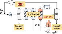
If not already part of the standard sampling and analysis scheme implemented to monitor plant performance, condensate samples can be taken from the feed gas and regeneration gas KO drums for analysis. As before, the dataset collected should be analyzed for anomalies by a comparison with historical data, as well as with new plant data. The sampling scheme is presented in Fig. 2.
 |
|
Fig. 2. Sampling options in molecular sieve dehydration unit. |
Feed gas samples are collected and analyzed on a regular basis. However, this type of analysis will generate only a bulk composition—data that is needed for analysis but that does not generate information on trace components due to the limited amount of samples available. In general, when discussing the quality of gas samples, the subject of sampling reliability will inevitably arise.
As the molecular sieve dehydration unit (DHU) is still running, it will not be possible to extract molecular sieve samples from the vessels. However, if the cause for the beds’ underperformance is not easily identified, then molecular sieve samples should be taken and analyzed at the first opportunity.
Even when no problems are detected with the DHU, it is recommended to take and store samples during the planned changeout. In this manner, samples are available for comparison if the need arises. When vessels are opened and unloaded, close observation should be made as to whether signs are present of caking (clumps of molecular sieve particles), excessive dust formation, excessive discoloration and darkening of the sieve, and channeling (discoloration on the wall).
Fresh spent molecular sieve samples can be analyzed by a variety of commonly used techniques:3,7
- Bulk-crushing strength and plate-crushing strength analyses to determine whether particles maintained their strength
- Thermometric gravimetric analysis (TGA) adsorption measurements of capacity and mass transfer properties to determine if an excessive decrease has occurred in the water adsorption capacity of the adsorbent (i.e., to measure the degree of deactivation of the adsorbent)
- Pyrolysis combustion mass spectrometric elemental (PCME) and/or flash combustion analysis to determine the amount of coking
- Mercury porosity determinations provide information about the pore structure of a material and its degradation.
One of the more common failures seen in DHUs is the failure of the bottom support structure of the vessel.1,3,4 The bottom support is an essential structure in the vessel, as it must ensure proper flow distribution during regeneration. The bed rests on a support, with the bottom dome of the vessel having a void space. A bottom dome filled with ceramic balls will achieve the same goal.
The root cause of the problem is the continuous expansion and contraction of the bottom support during thermal cycles. If a weakness exists in the bottom support structure that can create a gap, then the molecular sieve particles will almost certainly find that hole. Once the molecular sieve starts flowing, it behaves like water and part of it will likely flow into the bottom dome.
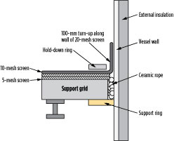
When opening a vessel, a clear indicator of an issue is the observation that a depression exists in the bed. Such a depression would create a channel—i.e., a path of least resistance manifesting itself as an early breakthrough of the bed. The molecular sieve in the bottom dome might also start to swirl, thereby grinding itself to dust and potentially creating problems for downstream equipment. A sketch of a “classic” bottom support structure is shown in Fig. 3.
 |
|
Fig. 3. Detailed sketch of a “classic” bottom support. |
The most common causes of bottom support failure for the classic bottom support are mesh screen installation failures, incorrect sizes of ceramic balls used, and incorrect installation of ceramic rope packing in the gap. An example of the latter is that the ceramic rope is too tightly packed, to the point where it loses its flexibility. Accumulation of dust between the support grid and the wall can result in a deformed support grid.
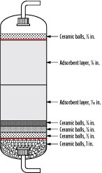
An alternative to the classic bottom support structure is the use of V-wire mesh screens, although these also have problems. Note: Care should be taken not to copy the design used in hydrotreater vessels. Although these reactors operate at high temperatures, they are not exposed to continuous temperature cycles. The other option is filling the bottom dome with ceramic balls, as shown in Fig. 4.
 |
|
Fig. 4. Sketch of an adsorber vessel with a bottom dome filled ceramic balls. |
The main advantage of filling the bottom dome with ceramic balls is eliminating issues with the bottom support as it is removed from the vessel. However, there are a few disadvantages to this method. The weight of the vessel increases, which can be a significant disadvantage for floating or offshore structures, where weight and plot space are major cost items.
Also, due to the larger inventory in the vessel, more heat is required for regeneration. Using the same regeneration flow means that more time is needed for regeneration (heating and cooling)—i.e., the minimum required uptake capacity increases. (Note: As discussed in Part 1, the minimum required uptake capacity is essentially determined by the minimum time needed for regeneration—i.e., the fastest time the system can be heated up and cooled down while ensuring that the beds are fully regenerated.) Such a system also has a higher CO2 footprint, another characteristic that is evaluated during modern design.
Proper loading of the molecular sieve beds is a critical operation. Thorough checks should be carried out during installation of the ceramic rope, the mesh screens, the ceramic balls and the first layer of molecular sieve. Unloading of the vessels should be carried out quickly, but safely, to minimize downtime. Before unloading takes place, the beds should be regenerated and purged to ensure that coadsorbed species, such as hydrocarbons and sulfur species, have been removed to acceptable levels.
One issue that is often neglected when operating DHUs is the disposal of spent adsorbent. Several aspects must be considered. Health, safety and environmental regulations demand that full personal protection equipment be worn during loading and unloading and during transport and storage. When loading and unloading, dust will be an issue. De-dusting before startup via piston purging is recommended. Local regulations for the handling and transport of possibly contaminated materials, as well as regulations for the safe destruction and recovery of spent adsorbents, will apply. The latter is usually not an issue with spent molecular sieves.
In general, it is important to realize that public concerns with regard to the handling and storage of possibly contaminated materials might endanger the license to operate. For spent molecular sieves, several disposal options are available. Usually, the sieve will be stored onsite, which is not a permanent solution. Spent molecular sieve is disposed of through a landfilling procedure that is completely controlled by local regulations.
One of the minimum requirements for landfilling is that a stabilization and leaching test confirms the safety of the landfilling option. Safe destruction is also an option, but this tends to be the most expensive one. In this context, vendors will usually assist with spent adsorbents. Some vendors even offer “cradle-to-grave” support services.
Other equipment items that create problems on a regular basis are the valves surrounding the vessels, which enable switching between the beds and guide the flow for adsorption and regeneration.8 The valves used in this environment must adhere to stringent specifications to provide a tight seal over a wide temperature range at high pressure. In a worst-case scenario, a valve would leak and deposit hot, wet regeneration gas on a bed in adsorption, thereby severely reducing the uptake capacity of that bed and possibly even inducing caking.
Few vendors can deliver these types of valves. In some designs (or applications, such as oxygen plants), regeneration is carried out at a lower pressure, which provides an additional driving force for desorption and thereby increases the efficiency of the regeneration. Such an operation raises the pressure differential over the valves, making a leak more likely to occur. This is one of the reasons that regeneration is carried out at the same pressure for temperature-swing adsorption (TSA) units, although it is not the main reason. The primary reason is that regeneration at a similar pressure occurs as the feed reduces the size of the compressor in the regeneration loop.
Takeaway. Despite careful design and operation of the molecular sieve dehydration unit, a variety of reasons (e.g., different feed composition or upstream equipment not working properly) could make it impossible to run the unit in the manner for which it was originally designed. If “quick fixes” are not possible, then a few options are available for consideration.
If the main purpose is to reach the next planned shutdown, and if some capacity is still left in two or more beds (assuming a 2 + 1 configuration), then one option is to continue operating at a reduced flow throughput. If one bed is severely underperforming, then another option is the combination of reduced flow throughput with running in 1 + 1 mode.
Unfortunately, these options will always carry a large price tag. In the case of the beds structurally underperforming, a denser molecular sieve9,10 could be combined with variable cycling as a debottlenecking option.
In summary, recommendations to help ensure that the DHU will run in a way that guarantees production of on-spec product and to ensure that the planned shutdown data will be available include:
- Conduct performance test runs on a regular basis
- Ensure proper design and operation of the upstream separator
- Use a guard layer
- Pay attention to the design and integrity of vessel internals
- Select good-quality molecular sieves
- Ensure proper loading of the molecular sieve
- Implement a regeneration profile that prevents the formation of liquid water
- Analyze spent molecular sieve samples.
Based on the data presented, it might seem as though molecular sieve units are the source of many problems in a gas processing plant. In reality, that is not the case. These units tend to be reliable and require relatively little operational attention. That in itself can be problematic when issues arise, however, as experience with troubleshooting these units is sometimes difficult to find. GP
Literature cited
- Mokhatab, S., W. A. Poe and J. Y. Mak, Handbook of Natural Gas Transmission and Processing, 3rd Ed., Gulf Professional Publishing, Burlington, Massachusetts, 2015.
- De Bruijn, J. N. H., M. A. Huffmaster, J. M. van de Graaf, P. F. A. van Grinsven and H. Grootjans, “Maximizing molecular sieve performance in natural gas processing,” presented at the 81st GPA Annual Convention, Dallas, Texas, March 11–13, 2002.
- Carlsson, A. F., J. B. Rajani and A. J. Kodde, “Finding the fountain of youth for a molecular sieve dehydration unit,” presented at the GPA Europe Annual Conference, Provence, France, September 22–24, 2004.
- Hawes, P., “Molecular sieves in natural gas processing,” presented at the GPA Europe Young Professional Training Day, Manchester, UK, February 11, 2016.
- Terrigeol, A., “Molecular sieves in gas processing: Effects and consequences by contaminants,” presented at the GPA Europe Annual Conference, Berlin, Germany, May 24–25, 2012.
- Meyer, P., “Molecular sieves troubleshooting,” presented at the 27th GPA Europe Annual Conference, Lisbon, Portugal, September 22–24, 2010.
- Herold, R., “Use analytical tools to investigate LNG molecular sieve underperformance,” Gas Processing, April 2015.
- Pack, B. and A. Shackleford, “Gas conditioning failures show need for design scrutiny,” Oil & Gas Journal, Vol. 111, Iss. 5, May 2013.
- Meyer, P., “Easy and sophisticated debottlenecking of molecular sieve plants,” Hydrocarbon World, Vol. 5, Iss. 1, 2010.
- Meyer, P., “Cost reduction using high-density molecular sieves,” presented at the 90th GPA Annual Convention, San Antonio, Texas, April 3–6, 2011.
 |
Ruud H. M. Herold was formerly senior process engineer at Shell Global Solutions International BV in Amsterdam, The Netherlands. He joined the company in 1986 and began working in the gas processing group in 2001, where he specialized in adsorption and catalytic processes used in gas and liquid treating. Mr. Herold holds an MSc degree in chemical engineering from the University of Amsterdam.
 |
Saeid Mokhatab is one of the most recognizable names in the natural gas processing industry. He has been actively involved in the design and operation of several gas processing plants around the world, and has contributed to gas processing technology improvements through 300 technical papers and two well-known handbooks (published by Elsevier in the US). He founded Elsevier’s Journal of Natural Gas Science & Engineering, and has given invited lectures on gas processing technologies worldwide. As a result of his work, Mr. Mokhatab has received a number of international awards and medals, and has been listed in prestigious biographical directories.


Comments