
Meet compression train base package design requirements for FPSOs—Part 1
Floating production, storage and offloading (FPSO) vessels are used throughout the world for the processing of oil and gas, for oil storage and for offloading to a tanker or through a pipeline. FPSOs can be subject to high winds and accelerations from the pitch, roll and heave of the sea. Continued safe operation of onboard equipment under both normal and adverse conditions is essential.
Base packages typically consist of a compressor, a gear and a driver, and are mounted on three anti-vibration mounts (AVMs) to minimize the loads and displacements being transmitted into the base package. The three-point mount bases require the analyses of a significant number of operational and upset load conditions to ensure safety and sustained equipment operation.
Transport and package lifting must also be evaluated. The normal operating loads include dead weight; acceleration due to FPSO; pitch, roll and heave; unbalance; torque; wind; and nozzle loads. The upset loads could include motor short-circuit torque, maximum acceleration and survival wind loading.
A modal and harmonic response analysis may also be required to ensure that response at key locations on the package remain within acceptable vibration limits due to rotor unbalance. It is important to perform these calculations early in the design phase, as design changes may be required to satisfy criteria.
The analytical procedures presented can apply to any driver, although motor drives are presented in most of the examples. These procedures also apply to either a standard gear or a variable hydraulic gear. The three-point mount examples show the use of AVMs, and the procedures could apply to gimbal mounts. Single-body compressor train examples are shown in the examples, and the presented procedures have also been applied to base packages with multi-body compressors.
FPSO worldwide distribution and operation. FPSO vessels first emerged in the mid-1970s. Since that time, 186 FPSOs have been commissioned into service; 147 of these remain in operation today. FPSOs are widely deployed offshore in Latin America, Asia, West Africa, the Middle East, the North Sea and most recently in the Gulf of Mexico.
The use of FPSOs appears to be still growing. The larger FPSOs have storage capacities in excess of 2 MMbbl of oil, and living accommodations for crews of between 100 and 200 people. They are also capable of processing up to 20 MMsm3/d of natural gas and injecting up to 300 MMbpd of water.1
 |
|
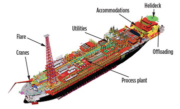
Fig. 1. Typical FPSO layout. |
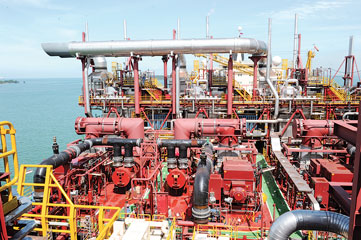
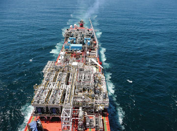
A typical FPSO layout is shown in Fig. 1, and an actual FPSO is shown in Fig. 2. Several types of turbomachinery may exist onboard, including gas injection compressors, gas lift compressors, export gas compressors, gas boosting compressors and fuel gas compressors. A view of two motor-driven compressor trains is shown in Fig. 3. Water-injection pumps and gas turbine-driven power generation trains may also be present, as shown in Fig. 4. The compressors and pumps are usually driven by mechanical-drive gas turbines or electric motors.
 |
|
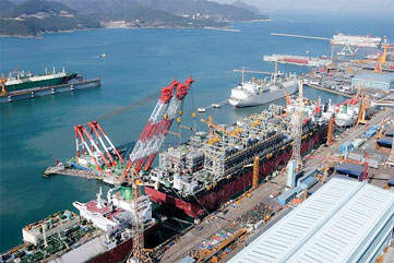
Fig. 2. An FPSO at a fabrication yard in Korea. |
 |
|
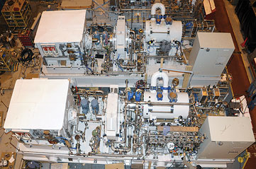
Fig. 3. Two motor-driven, gas-injection compressor trains showing the drive motor, speed-increasing gear and compressor mounted on a common baseplate, together with a base-mounted lube oil system, dry gas seal system and local control panel. |
 |
|
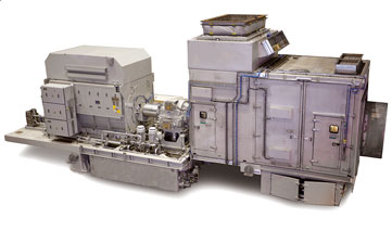
Fig. 4. A typical aeroderivative gas turbine-driven electric generator destined for operation on an FPSO. |
In most instances, a speed-increasing gearbox is also used between the driver and the driven equipment. It is common to mount the compressor, gear and driver on a common, single-lift baseplate. The baseplate is fabricated from structural steel and contains mounting pedestals for each piece of equipment.
In some cases, all of the auxiliary equipment needed to support the compressor and its drivers (such as a lubricating oil system, a dry gas seal system, instrumentation, and a local control panel) are also mounted on or within the baseplate. Some FPSOs have utilized steam turbine-driven electric generator sets. Fig. 5 and Fig. 6 show two steam turbine-driven generators of different powers. Both are mounted on the top decks of their respective FPSOs.
 |
|
Fig. 5. Two 27-MW steam turbine generator sets on board the |
 |
|
Fig. 6. Three 24-MW condensing steam turbine generator sets on board the Peregrino FPSO. |
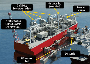
FPSO technology has matured significantly over the years, with the vessels gradually growing larger and more complex. As many as 50 risers can be connected through its mooring system. These risers have more sophisticated processing capability, with the latest evolution being the introduction of natural gas liquefaction to an FPSO. When an FPSO is utilized for the production of LNG, it becomes known as an FLSO. A typical FLSO design is shown in Fig. 7.
 |
|
Fig. 7. FLSO design concept. Used with permission from Excelerate Energy. |
The world’s first FLSO is undergoing commissioning at this time, but several more FLSOs are in the planning stages. This innovative method for producing oil and natural gas can have several advantages compared to conventional offshore platforms, the primary examples of which are cost-effective production of smaller-sized reservoirs and the ability to operate in waters considered too deep for conventional platforms and portability. Many FPSOs can disconnect from their risers, allowing them to be moved away from hurricanes and severe storms.2 The technology must overcome some challenges, including mooring system development, turret system development, flexible riser systems, safe handling of flaring, government regulations, financing, and coping with wave motion.
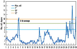
This last challenge—wave motion—warrants additional discussion. Fig. 8 illustrates the peak tilt angle experience by a typical FPSO during a 6-hr time period. Note the random fluctuation of the tilt, which achieves a maximum value of more than 18°. (Note: For the sake of comparison, the cruise industry considers a tilt of 15° to be extremely severe. In such events, cruise passengers are usually injured by falls and sliding objects; some have even been thrown overboard.)
 |
|
Fig. 8. Wave motion roll angle experienced by an FPSO. |
On an FPSO, the ability to properly mount and secure rotating machinery is of paramount importance. Of critical importance are the mechanical design of the baseplates upon which the turbomachinery is supported, and the mounting of the baseplate to the topsides deck. The baseplate must be properly secured to and support the rotating equipment and the loads mounted on it, and it must be able to handle the forces and moments imposed by the FPSO hull and deck motions.
Typical base package designs. The typical base package design uses torque boxes or torque tubes to provide torsional and bending stiffness. The flexural stiffness is required for dead weight, package lift and ship heave. The torsional stiffness limits the overall base package twist resulting from both vessel pitch and roll, and from wind loads. Adequate torsional stiffness is required to limit the relative displacements between the shaft ends. This relative displacement must be limited both on the high-speed end between the compressor and high-speed gear, and on the low-speed end between the driver and the low-speed gear. Adequate bending stiffness is required for package lifting and ship heave.
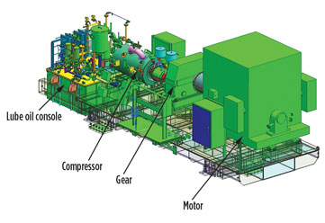
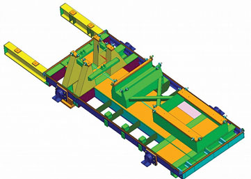
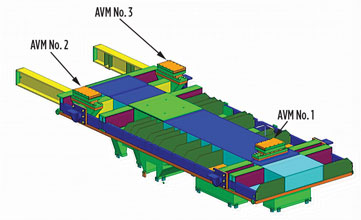
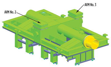
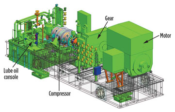
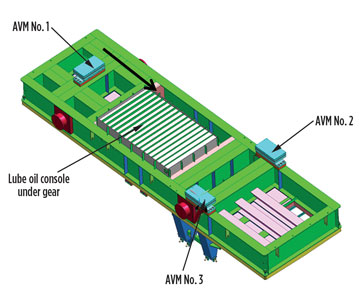
Fig. 9 shows a motor, gear and compressor package supported by a torque box design. The lube oil console is cantilevered off the end of the base. A top view showing the base (skid) structure is shown in Fig. 10. The primary flexural and torsional member is the fabricated torque box. Fig. 11 shows the bottom view and the positioning of the three AVMs. Two AVMs are located under the compressor, and one is located under the motor.
 |
|
Fig. 9. Typical torque box base package design with motor, gear, compressor and lube oil console. |
 |
|
Fig. 10. Top view of torque box base. |
 |
|
Fig. 11. Bottom view of torque box base. |
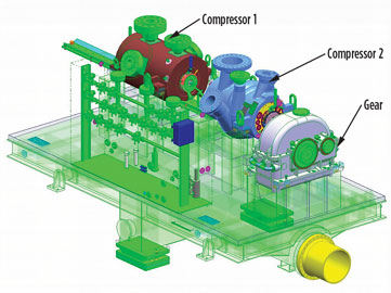
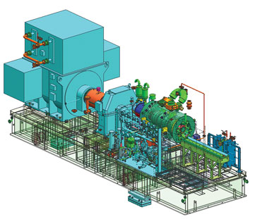
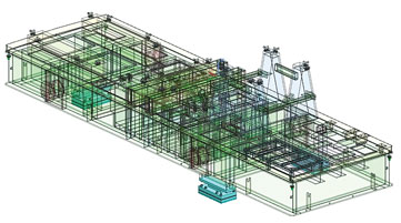
An analytical model of a torque tube concept is shown in Fig. 12 and Fig. 13. This package includes two compressors and a gear. The base is bolted to another base that includes the driver, so this package includes only the two AVMs under the compressor. The base with the driver includes one AVM under the driver. The torque tube provides flexural and torsional stiffness.
 |
|
Fig. 12. Typical FPSO base package with torque tubes. |
 |
|
Fig. 13. Top view of base showing torque tubes. |
A third design concept does not use either a torque tube or a torque base; instead, wide flange beams are used on the perimeter of the base and for the main transverse beams. This design typically results in higher torsional and bending stiffnesses, but it also results in a heavier base. Fig. 14 shows a compressor, gear and motor package supported by wide flange beams with the lube oil console cantilevered off the end of the base. The flexural stiffness is provided through the two large, wide flange beams that run in the longitudinal direction. These two beams also provide the support for the cantilevered lube oil console. The longitudinal beams, together with the transverse beams, provide the torsional stiffness.
 |
|
Fig. 14. Typical FPSO base package with wide flange beams. |
Base design considerations. A number of considerations affect the base design. The required flexural strengths must be met, and this requires the detailed analyses discussed in this article. Bases fabricated from wide flange beams have been shown to reduce shaft-end relative displacements, but they have also been shown to be 18%–22% heavier. It is important that the shipbuilder has a good estimate of the total package weight.
Costs of material and fabrication, including welding, are important. Total base costs are typically obtained from a number of base fabricators. The cost to manufacture a beam base vs. a box or torque tube base varies by manufacturer.
In many cases, it is advantageous to include the lube oil console under the gear as opposed to cantilevering it off the end of the base. Fig. 15 shows a base beam with the lube oil console under the gear. Top and bottom views of the base are shown in Fig. 16 and Fig. 17. The entire base package is shorter, and space is at a premium on the FPSO.
 |
|
Fig. 15. Wide flange beam base with lube oil console under the gear. |
 |
|
Fig. 16. Top view of wide flange beam base with lube oil console under the gear. |
 |
|
Fig. 17. Bottom view of wide flange beam base with lube oil console under the gear. |
The other advantage is that it is easier to meet the API 2.5° drain requirement from the gear to the lube oil console. Typical ship roll, pitch and heel are 12°, 3° and 1°, respectively. For a 3° ship pitch, the pipe slope must be 3° plus 2.5°, or 5.5°. If the lube oil console is positioned off the end of the base, it might be too long to achieve the required drain angle. If the ship roll is specified as 12°, then the drain would be 14.5° in the lateral direction if the pipe needs to be run laterally for a certain distance.
The torque tube design can also accommodate a lube oil console under the major equipment. However, the disadvantage of including the lube oil console under the gear for a torque tube design is that there is no large center torque tube extending from one end of the base to the other. It must be replaced by two smaller torque tubes that run along the sides of the lube oil console.
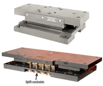
Three-point mounts. Three mounts are used for each package, and these are key to the successful operation of the package onboard the FPSO. Typical AVM designs are shown in Fig. 18.
 |
|
Fig. 18. Typical AVM designs. |
The top pad of each AVM is bolted to the base, and the bottom pad is bolted to the ship deck. Wire mesh cushions (WMCs) are used to provide the stiffness. These cushions are stacked and positioned to provide the proper stiffness in each direction per the package requirements. The AVMs also provide rotational flexibility. Cushioned uplift restraints provide stiffness in the vertical uplift direction during ship heave or during ship pitch and roll.
The vertical movement at the mount position is limited to 3 mm–6 mm. All mounts can gimbal by 0.35° in all three rotational directions. For a 4.6-m-wide base, one side could displace upward by 13 mm, and the other side could displace downward by 13 mm. WMCs have high damping (15% to 20% of critical damping). Three-point mounts are easier to install than a multi-point system, which is difficult to properly install. The bolts between the base and pads, and between the pad and deck, are slip-critical. Shear pins are used in some designs.
The advantages of AVMs over gimbal mounts are:
- AVMs are generally considered to offer better vibration isolation
- AVMs are not as high as gimbals, which raises the height of the overall package
- AVMs do act as gimbals in that they allow rotation, but the rotation is limited compared to a gimbal
- No significant cost difference is observed
- No sliding large forces can be transmitted into the skid from the deck, although gimbals can be designed with sliding.
The advantages of gimbal mounts include:
- More rotation is allowed if needed (15° for gimbals vs. 0.375° for AVMs), which is advantageous in situations where higher rotation is seen between the top and bottom plates of the mounting system
- Gimbals do not add to displacements at pipe connections, and there is no relative (dynamic) movement between the deck and the package.
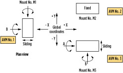
AVMs are more often used because of their high damping and successful experience with their use. AVMs provide stiffness and damping in the axial, lateral and vertical directions. Fig. 19 shows typical AVM placement. Many early designs included two AVMs under the driver and one under the compressor; however, designs with two AVMs under the compressor and one under the driver have been shown to more easily meet displacement criteria. One reason for this is that incorporating two AVMs under the compressor limits the compressor rotation due to the nozzle loads, vessel pitch and roll, and other operational loads. Additionally, displacement limits are more stringent for the high-speed coupling on the compressor side than for the low-speed coupling on the driver side.
 |
|
Fig. 19. AVM fixed and sliding directions to isolate base package deflection from FPSO deck twist and bending |
The AVMs isolate the base package from the vessel hull and deck in two ways. First, the AVMs are heavily damped, decreasing the amplitude of base package displacement. This large frictional damping is provided by the WMCs. As a result of this damping, amplification factors for an AVM are typically 2.5. As a comparison, amplification factors for coil springs and rubber are 20 and 10, respectively. Damping is lower for vibration loads like rotor unbalance, and very good vibration isolation between the base package and the deck is realized. The AVMs are particularly effective in preventing structure-born noise from being transmitted to the package.
Second, sliding is allowed in two directions, as shown in Fig. 19 where AVM No. 1 is allowed to slide in the axial (X) direction and AVM No. 3 is allowed to slide in the lateral (Y) direction. This sliding prevents deck twist from being transmitted to the base package. As the deck bends and twists, the package has the capability to slide in the axial and lateral directions, minimizing the twist and bending that are transmitted into the base.
The AVM sliding is activated under normal operational loads and upset loads. Sliding does not occur as a result of vibrational loads because the smaller vibrational loads cannot overcome the friction. For this reason, the sliding is activated in the analytical model for the static analyses of the operational and upset loads. For dynamic analyses (harmonic response), the rotor unbalance loads are not high enough to overcome the friction, even in the sliding direction. The three-point mount also serves to keep the package level.
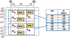
A typical arrangement of base packages on an FPSO deck is shown in Fig. 20. The axial direction of the equipment is generally installed parallel to the ship’s longitudinal direction, and the package’s lateral direction is parallel to the athwartship direction. The vessel’s deck stiffness under each AVM is provided by the shipbuilder for inclusion in the analytical model. If not provided, deck stiffnesses from similarly sized jobs are used until the final deck stiffnesses are available. Inclusion of the deck stiffness in the operational and upset load analyses (pseudo-static analyses) have been shown to increase shaft-end relative displacements by as much as 8%. Therefore, it is conservative to include them.
 |
|
Fig. 20. FPSO deck location where stiffness is required. |
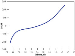
AVM stiffness values are determined from load-deflection curves (Fig. 21). The individual WMCs are tested to determine their load-deflection curve. The load-deflection curve is then determined analytically, based on how the WMCs are stacked and arranged inside the AVM. A linear stiffness value is extracted from this curve and used in the analysis. This process is accomplished by using the tangent stiffness at the typical load.
 |
|
Fig. 21. AVM load vs. deflection curve supplied by AVM vendor. |
The AVM vendor requires load data on each AVM for all load cases to properly design the AVM. The AVM is designed and built concurrently with the base build and the analysis. Therefore, preliminary values of AVM stiffness are used early in the analysis phase. This can be accomplished in one of two ways. AVM load-deflection curves from similar packages can be utilized, or the AVM stiffness can be estimated. Since the AVMs are designed to give a response of 12 Hz–15 Hz in the vertical direction, the preliminary vertical stiffness for each AVM can be calculated from Eq. 1:
(1)
where:
Kv = AVM stiffness in vertical direction
Fn = 12 Hz to 15 Hz
M = R/g = total mass supported by AVM (R = AVM vertical reaction)
The AVM load-deflection curves, such as the one in Fig. 21, are typically supplied late in the analysis phase. Then, the most critical cases are rerun using the final AVM stiffness values. If the preliminary AVM stiffness values are adequately estimated, then the final results typically do not vary from the preliminary results by more than 1%–2%.
Takeaway. Worldwide distribution of FPSOs and typical applications have been discussed. The three AVMs dampen the response and isolate the base package from the FPSO deck. Three base designs have been discussed. Torque box and torque tube designs provide torsional stiffness and result in lighter base packages. Larger I-beam designs are heavier, but they provide higher torsional stiffness and allow for a shorter package by including the lube oil reservoir under the base.
The shaft-end relative displacement criteria have been shown to be more limiting than the stress criteria. Significant detail is included in the finite element analysis (FEA) models to accurately calculate the shaft-end relative displacement. These details include more accurate modeling of the rotors, bearing connections, compressor pedestal sliding, and keel blocks. The importance of initiating the analysis while using preliminary data is emphasized as the base manufacture and analysis phases are conducted concurrently. Base modifications that are identified early in the manufacturing cycle are much easier to implement than those identified later.
Improvements in data gathering, FEA model preparation and the automation of worst load case combinations have resulted in a 40% reduction in analysis time. The analytical models provide a valuable tool in assessing the suitability of three-point base package design for operation on FPSOs.
Part 2, to be published in December, will examine data gathering for the FEA and construction of the FEA model. GP
Literature cited
- “Axial and centrifugal and expander compressors for petroleum, chemical and gas industry services,” American Petroleum Institute (API), Vol. 617, 7th Ed., July 2002.
- Mastrangelo, C., K. Barwick, L. Fernandes and E. Theisinger, Petrobras America Inc., “FPSOs in the Gulf of Mexico,” January 9–11, 2007, Kenner, Louisiana, online: http://offshorelab.org/documents/FPSOs_in_the_GoM.pdf
Notes
This article was presented at the Asia Turbomachinery and Pump Symposium in Singapore, February 22–25, 2016, and is published with permission of the Turbomachinery Laboratory.
 |
Edward Abraham is Principal Solid Mechanics Engineer for the Dresser-Rand business, which is part of Siemens Power & Gas. He has performed numerous analyses of turbomachinery components, including cases, impellers, lifters, rotors and base packages.
 |
Harry Miller is Director of Emerging Technology for the Dresser-Rand business. He has authored several technical papers and articles, has been awarded and has contributed to several patents, and has received the Dresser Industries Annual Technical Achievement Award. He is also a member of the American Society of Mechanical Engineers.


Comments