
Process selection and recent design innovations for LNG plants—Part 2
I. S. Al-Mutaz, I. Wazeer and R. Khan, King Saud University, Riyadh, Saudi Arabia;
and A. Chafidz, Semarang State University, Central Java, Indonesia
Different types of natural gas liquefaction plants have been developed across the world to meet rising demand for LNG. The selection of LNG technology involves parameters such as equipment (e.g., compressors, turbines, heat exchangers, etc.) and process definitions (e.g., pressure levels, temperature range, type of refrigerant, etc.).
However, LNG technologies are cost-intensive, as they require a large amount of energy for the processes of compression and refrigeration. Therefore, further developments are required to save costs and improve the efficiency of existing gas liquefaction processes.
Here, existing and future traits of LNG processes are analyzed in view of recently constructed plants. The authors also examine process selection criteria for LNG plants, as well as developments and innovations in LNG technology.
Process selection criteria
The technology selection for an LNG terminal is based on technical and economic considerations. Before beginning a project, sufficient process details must be established to describe the core equipment and standard operating parameters (SOPs), to assess possibilities using applicable norms and to define the capital and operating costs for each licensor.
The liquefaction process selection is tied to project economics. For this reason, it should be addressed at an early stage of the project, preferably during the feasibility report and pre-FEED phases. Technical considerations include licensor experience, consistency, reliability and availability; the productivity of the process; ecological factors and factors associated with site location. Economic considerations include capital investment; operational and lifespan costs, including units upstream and downstream of the LNG terminal; and utility and offsites costs.
The process design selection for LNG is an optimization among the elements of refrigerant selection and composition, the design of the heat exchanger and the heat transfer area. Also, the refrigerant power consumption must be matched to accessible compressor/driver capacity.
For mid-scale LNG plants, mixed-refrigerant (MR) cycle plants are the best choice. Propane-precooled MR, cascade or dual-refrigerant cycles are preferred for baseload LNG plants, due to their higher efficiency.23 Important parameters for selecting LNG technology are described in the following sections.
Thermal efficiency. The ratio of the total higher heating value (HHV) of the liquefied product to the total HHV of the feed gas is known as thermal efficiency. Various factors affect thermal efficiency, including feed gas pressure and temperature, gas composition, site temperature and pressure. Thermal efficiency is a tradeoff between capital costs and lifecycle costs. When calculating liquefaction thermal efficiency, it is necessary to include the selection of the gas turbine driver, end-flash design and waste heat recovery in the calculation.24
Equipment selection. The selection of appropriate equipment for the LNG terminal is the most important step in the economic consideration of the project. Equipment is selected on the basis of efficiency, cost and the licenser’s successful track record and experience. The technology should also be able to accommodate step changes in the plant, such as increases in size and efficiency improvements. It is also important to consider factors like gas composition, molecular weight, temperature, pressure, compression ratio and flowrate of the refrigerant when selecting rotary equipment.
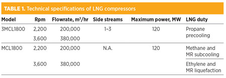
Compressor. In baseload plants, the selection of the centrifugal compressor is normally an economical choice of a refrigeration compressor, due to its high volumetric flow. Axial compressors are more favorable for higher flowrates, but they must be operated at lower pressure ratios as compared to MR compressors. If the refrigeration process is subjected to pass from a high-efficiency axial compressor, then the compressor can be utilized as first-stage compression, with some optimization of design and compression train. The larger models of compressors used are shown in Table 1, along with their respective technical specifications.
 |
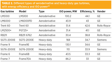
Driver selection. Early on, steam turbine drivers were used in baseload liquefaction plants due to their reliability. Later, steam turbine drivers were replaced with gas turbine drivers due to the increase in size and efficiency. Gas turbines are easy to operate compared to steam turbines, which are more complex and not appropriate for remote areas. Based on their efficiency and weight, gas turbines can be classified as heavy-duty industrial types (i.e., frame turbines) and aeroderivatives.25,26 Aeroderivative gas turbines are lightweight, easy to maintain and can be operated with a higher compression ratio and higher thermal efficiencies (about 25%), compared to industrial gas turbines.27,28 Different types of aeroderivative and heavy-duty gas turbines are listed in Table 2.29
 |
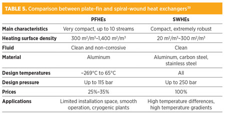
Heat exchanger. The main heat exchangers used in gas liquefaction process trains are: plate-fin heat exchangers (PFHEs) and spiral-wound heat exchangers (SWHEs). The main advantages of PFHEs are their compactness, low equipment weight, small footprint and typically lower capital cost. They can be configured to accommodate different processes with multiple exchangers. However, since PFHEs are made of aluminum, they are also more vulnerable to mechanical damage and damage from thermal shocks.
SWHEs are designed with a greater internal heat transfer area and, therefore, can operate within a larger temperature gradient. In addition to the wider surface area, an advantage of SWHEs is their higher proven tolerance to thermal shocks. However, because of the fixed heat exchange configuration, the SWHE design has a limited flexibility to handle different feed gas compositions.
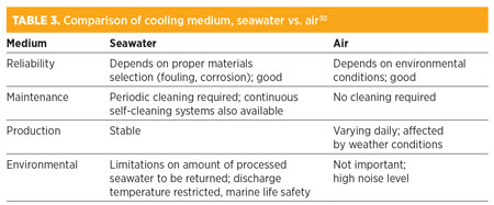
Cooling medium. The cooling medium of an LNG plant refers to the cold-side fluid in the refrigerant condensers. Approximately 70% of operating LNG plants use seawater as a cooling medium directly or indirectly; the remainder use air-cooled condensers for cooling purposes. The main differences between seawater condensers and air condensers are listed in Table 3.
 |
Developments and innovations in LNG
To meet increasing demand for LNG, new liquefaction plants must be built to take advantage of unconventional gas sources, as well as new discoveries. Efficiency and environmental impact must be given special consideration. To this end, new ideas, developments and innovations in the LNG supply chain are described in the following sections.
Important factors, such as improved liquefaction equipment design, larger and higher-efficiency drivers, NGL recovery, LNG regasification and LNG cold utilization are discussed with regard to detail and application.
LNG imports and exports. Major LNG-importing countries include South Korea, Japan, Taiwan and some European countries.32 Japan is the largest LNG importer worldwide.33,34 Major LNG exporters include Qatar, Malaysia, Australia and Indonesia.31,35 It is expected that Australia will become the largest LNG exporter in the world by 2018.33 Historically, the leading market for LNG is the Asia-Pacific region.
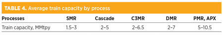
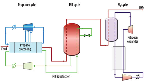
Larger LNG trains. Substantial improvements have been made in the LNG industry to increase the capacity of trains by applying a proprietary, three-cycle process. The three cycles consist of propane, MR and nitrogen. In 2008, six trains with a total capacity of 7.8 MMtpy were constructed in Qatar. Average train capacities by different proprietary LNG processes are listed in Table 4.
 |
The configuration of the proprietary, three-cycle process is shown in Fig. 1. The propane cycle is used for precooling, while the MR is used in the main cryogenic heat exchanger (MCHE) to liquefy natural gas. The third cycle—the nitrogen expander loop—allows final subcooling.
 |
|
Fig. 1. Flow diagram of the APX process. |
A train size of greater than 10 MMtpy is now achievable with large heat exchanger designs and the latest gas turbine drivers. By using all three cycles, it is possible to achieve low production cost and high efficiency. Literature has claimed that maximum efficiencies can be achieved using the APX, DMR and C3MR processes, with the POCP process offering around 90%.36–38
Main heat exchanger. In the past, the MCHE was limited to a maximum weight of 310 metric t and a diameter of 4.6 m, due to the limited power available from the compressor drivers. Larger trains have been developed by increasing driver sizes for maximum power.
At present, two major types of heat exchangers are widely used in the LNG industry—PFHEs and SWHEs. PFHEs have a low weight, small size, low cost, high effectiveness and high thermal capacity. SWHEs are used in single-phase and two-phase applications, and they have a wide pressure and temperature range. LNG production increases with higher tube-side design pressure, and specific power decreases.22 A comparison between PFHEs and SWHEs is given in Table 5.
 |
NGL recovery and liquid expanders. A scrub column design can be used to combine the LNG liquefaction process with NGL recovery. One cryogenic process using single-column overhead recycle technology has been applied around the world for propane recovery. Up to 99% of propane can be recovered using this process. Around 40% of ethane is recovered by applying the process in “incidental” mode.40
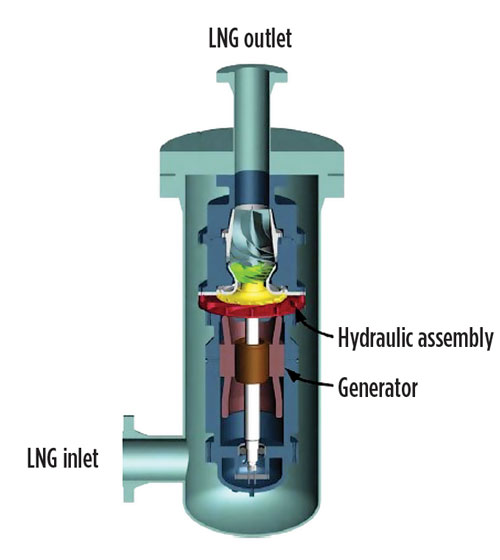
Annual plant revenues can be increased by adding liquid expanders to an LNG processing train. In a typical LNG process, a Joule-Thompson valve is used to reduce pressure in refrigeration units. Recently, however, liquid expanders have been introduced in new liquefaction plants. The liquid expanders function like pumps in reverse. Liquid enters at a higher pressure and leaves at a lower pressure. Process efficiency can be improved with the use of flashing liquid expanders (Fig. 2).41–43
 |
|
Fig. 2. Assembly of LNG liquid expander.44 |
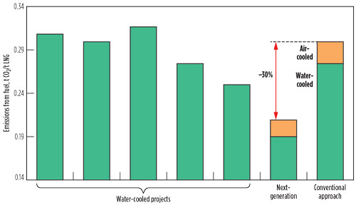
Future LNG plants. Large LNG trains in the 8 MMtpy–9 MMtpy capacity range can be located only where gas reservoirs are sizable. In the future, LNG trains in the range of 3 MMtpy–6 MMtpy will become more prominent. The LNG industry is focusing on methods to increase energy efficiency, minimize overall environmental impact and reduce CO2 emissions. Efficient gas turbines, large motor drivers, combined-cycle power plants and efficient NGL/LNG integration are important for next-generation liquefaction plants. Innovative developments will reduce CO2 emissions in next-generation plants, as illustrated in Fig. 3.7
 |
|
Fig. 3. Reduction in CO2 emissions from LNG plants in future. |
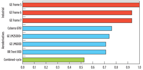
Fig. 4 shows relative CO2 emissions from gas turbines. Due to their higher thermal efficiencies, aeroderivative gas turbines yield lower CO2 emissions than industrial gas turbines. However, combined-cycle power plants—in which exhaust heat from the gas turbine is recovered and used in power generation—produce the lowest CO2 emissions. Until recently, these combined-cycle power plants were considered as the most efficient power plants. Aeroderivative gas turbines are more favorable for remote and offshore installations because they can be started under settle-out pressure and without helper motors.45,46
 |
|
Fig. 4. Relative CO2 emissions from industrial gas turbines and aeroderivative gas turbines. |
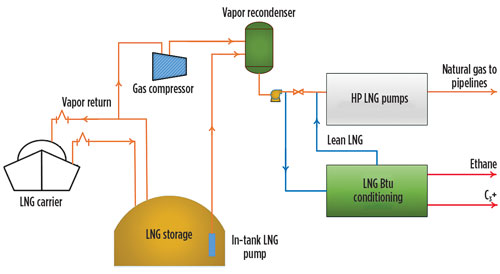
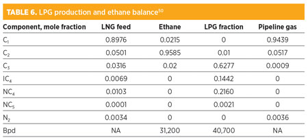
LNG regasification. The Organic Rankine power cycle produces power by using LNG as a cooling medium.47–49 An LNG cryogenic energy cascade process has been developed to supply refrigeration to numerous operators, including power plants, LPG storage, petrochemical plants and oil refineries. An LNG Btu-conditioning system can be used instead of a nitrogen-injection unit, and can be integrated to the LNG plant as shown in Fig. 5. The purpose of a Btu-conditioning system is to remove ethane, propane and heavier hydrocarbons to produce a lean LNG. Almost 97% of propane and 70% of ethane can be recovered using this process. It also reduces the Wobbe Index, as shown in Table 6.50
 |
|
Fig. 5. LNG terminal with BTU control. |
 |
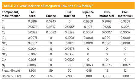
As a transportation fuel, LNG has become more attractive because it is cheaper than oil. A configuration for the coproduction of vehicle-grade LNG and CNG is shown in Fig. 6. To facilitate the power supply, an expander cycle-based cryogenic power generator can be used in the design. Table 7 shows the production of 59 MMscfd of ethane, 200 Mgpd of vehicle-quality fuel and 51 Mbpd of rich LPG at an integrated plant.51
 |
|
Fig. 6. Flow diagram of integrated LNG regasification and CNG production. |
 |
Takeaway
This work outlines different aspects of and developments in LNG production processes. One important new trend is the combination of an LNG regasification unit with a power plant. Significant research has been performed on the LNG production chain and the management of related security risks in the storage, handling and transport of LNG. The efficiency of the LNG production chain can be improved by optimizing process components, especially those related to the regasification and liquefaction processes.
To meet growing demand for LNG, continuous developments have been made to improve process technologies for liquefaction. Technical (e.g., process, reliability, efficiency, site and environmental conditions, etc.) and economic (e.g., lifecycle costing, operating costs and capital costs) factors must be considered during process and equipment technology selection. Research work is being carried out to introduce innovative methods for increasing energy efficiency, reducing CO2 emissions and minimizing overall environmental impact.
Aeroderivative gas turbines are recommended for remote and offshore installations because they are lightweight and more energy efficient than industrial gas turbines. Also, although no major incidents have been reported in the LNG industry, continuous improvements are required to maintain safety records. Over the past decades, most research studies have concentrated on improving process efficiency without estimating capital costs. Further research studies and improvements are required to maximize profits in combination with process efficiency. GP
Acknowledgment
The authors would like to extend their sincere appreciation to the Deanship of Scientific Research at King Saud University for its funding of this research through Research Group Project number RGP-224.
Literature cited
23. Finn, A., G. Johnson and T. Tomlinson, “Developments in natural gas liquefaction,” Hydrocarbon Processing, Vol. 78, 1999.
24. Yates, D., “Thermal efficiency—Design, lifecycle and environmental considerations in LNG plant design,” Gastech, October 13–16, 2002, Doha, Qatar.
25. Avidan, A., F. Richardson, K. Anderson and B. Woodard, “LNG plant scale-up could cut costs further,” Petroleum Economist, March 2001.
26. Kleiner, F., S. Rausch and J. Knabe, “Increase power and efficiency of LNG refrigeration compressor drivers: All-electric-driven plants can offer many benefits,” Hydrocarbon Processing, Vol. 82, 2003.
27. Meher-Homji, C. B., D. Messersmith, T. Hattenbach, J. Rockwell, H. Weyermann and K. Masani, “Aeroderivative gas turbines for LNG liquefaction plants—Part 1,” ASME Turbo Expo 2008: Power for Land, Sea, and Air, 2008.
28. Meher-Homji, C., D. Messersmith, T. Hattenbach, J. Rockwell, H. Weyermann and K. Masani, “Aeroderivative gas turbines for LNG liquefaction plants—Part 2,” ASME Turbo Expo 2008: Power for Land, Sea, and Air, 2008.
29. Van Loon, M. and S. van de Lisdonk, “Shell makes progress on FLNG and next generation of onshore LNG plant design,” LNG Journal, 2012.
30. Coyle, D. A. and V. Patel, “Processes and pump services in the LNG industry,” TAMU Pump Show, Texas A&M University International Pump Users Symposium, 2005.
31. Kumar, S., H.-T. Kwon, K.-H. Choi, J. Hyun Cho, W. Lim and I. Moon, “Current status and future projections of LNG demand and supplies: A global prospective,” Energy Policy, Vol. 39, 2011.
32. Dorigoni, S., C. Graziano, and F. Pontoni, “Can LNG increase competitiveness in the natural gas market?” Energy Policy, Vol. 38, 2010.
33. Leather, D. T. B., A. Bahadori, C. Nwaoha and D. A. Wood, “A review of Australia’s natural gas resources and their exploitation,” Journal of Natural Gas Science and Engineering, Vol. 10, 2013.
34. Vivoda, V., “LNG import diversification in Asia,” Energy Strategy Reviews, Vol. 2, 2014.
35. Wood, D. A., “A review and outlook for the global LNG trade,” Journal of Natural Gas Science and Engineering, Vol. 9, 2012.
36. Roberts, M. J., Y. N. Liu, J. M. Petrowski and J. C. Bronfenbrenner, “Large capacity LNG process—The AP-X cycle,” Gastech, October 13–16, 2002, Doha, Qatar.
37. Bronfenbrenner, J. C., M. Pillarella and J. Solomon, “A suitable process,” Hydrocarbon Engineering, Vol. 14, 2009.
38. Ransbarger, W., “A fresh look at LNG process efficiency,” Hydrocarbon Engineering, Vol. 12, 2007.
39. Thulukkanam, K., Heat Exchanger Design Handbook, 2nd Ed., CRC Press, Boca Raton, Florida, 2013.
40. Thompson, G., J. Adams, A. Hammadi, S. Kaabi and P. Sibal, “Qatargas II: Full supply chain overview,” LNG 14, Qatar, 2004.
41. Houser, C. G., R.-J. Lee and N. Baudat, “Employing liquid expander to recover energy associated with flashing of a pressurized liquid stream and employing said recovered energy to compress the flashed vapor streams; liquefaction of natural gas; cryogenics,” Google Patents, 2001.
42. Barclay, M. and T. Shukri, “Enhanced single mixed refrigerant process for stranded gas liquefaction,” LNG Consultants, 79th Annual GPA Convention, Atlanta, Georgia, 2000.
43. Qualls, A. P. E., “Liquid expander in the Phillips Optimized Cascade LNG process,” LNG 14, Qatar, 2004.
44. Kimmel, H. E. and S. Cathery, “Thermofluid dynamics and design of liquid-vapour two-phase LNG expanders,” GPA Europe, Technical Meeting on Advances in Process Equipment, Paris, France, 2010.
45. Giampaolo, T., Gas Turbine Handbook: Principles and Practices, Fairmont Press, Lilburn, Georgia, 2014.
46. Meher-Homji, C., D. Yates, H. P. Weyermann, K. Masani, W. Ransbarger and S. Gandhi, “Aeroderivative gas turbine drivers for the ConocoPhillips Optimized Cascade LNG process—World’s first application and future potential,” LNG 15, Barcelona, Spain, April 2007.
47. Stradioto, D. A., M. F. Seelig and P. S. Schneider, “Performance analysis of a CCGT power plant integrated to a LNG regasification process,” Journal of Natural Gas Science and Engineering, Vol. 23, 2015.
48. LaRocca, V., “Cold recovery during regasification of LNG, Part 2: Applications in an agro food industry and a hypermarket,” Energy, Vol. 36, 2011.
49. LaRocca, V., “Cold recovery during regasification of LNG, Part 1: Cold utilization far from the regasification facility,” Energy, Vol. 35, 2010.
50. Smith, A. and J. Y. Mak, “LNG regasification and utilization,” Atlantic Oil and Gas, 5th Annual Meeting, 2005.
51. Mak, J. Y., D. B. Nielsen, D. T. Schulte and C. Graham, “A new and flexible LNG regasification plant,” GPA Annual Convention Proceedings, 2004.
 |
Ibrahim S. Al-Mutaz is a Professor of Chemical Engineering at King Saud University in Riyadh, Saudi Arabia. His expertise lies in process engineering, process plant troubleshooting and rehabilitation, process equipment, process plant performance and efficiency, process technology, simulation and optimization of desalination processes, desalination and water treatment, optimum production of water and power, groundwater pretreatment facilities and environmental protection. He has published approximately 200 papers in journals and conferences, as well as 13 books. Dr. Al-Mutaz earned his BSc degree in chemical engineering from King Saud University in Riyadh, Saudi Arabia. He earned his PhD in chemical engineering from Yale University in New Haven, Connecticut.
 |
Irfan Wazeer is a Researcher in the Chemical Engineering Department at King Saud University. His research interests center on the applications of ionic liquids and deep eutectic solvents. He has also been involved in projects for water desalination, natural gas processing and liquid-liquid extraction. He earned his BSc degree in chemical engineering from the University of Engineering and Technology in Lahore, Pakistan. He was also awarded a fully funded scholarship from Saudi Arabia’s Ministry of Higher Education to attend King Saud University, where he earned his MSc degree in chemical engineering.
 |
Rawaiz Khan is a Researcher in the Chemical Engineering Department at King Saud University. He graduated from Hamdard University in Karachi, Pakistan in 2009. In 2012, he joined King Saud University as a Research Scholar on a fully funded scholarship offered by Saudi Arabia’s Ministry of Higher Education, under the Attracting Outstanding Faculty and Researchers Program. He completed his MSc degree in chemical engineering at King Saud University in 2015. He has also worked in the petrochemical industries of Pakistan and the UAE.
 |
Achmad Chafidz Mas Sahid is a Lecturer in the Chemical Engineering Department at Semarang State University in Semarang, Indonesia. Previously, he worked as a Researcher at the SABIC Polymer Research Center at King Saud University. His research areas include processing and characterization of polymer nanocomposites; application of supercritical CO2 fluid in the pharmaceuticals industry; development of portable, solar-powered membrane distillation systems for remote areas; and development of flotation reagents for Saudi phosphate ores. He received his BSc degree in chemical engineering from the Sepuluh Nopember Institute of Technology in Surabaya, Indonesia in 2007. He earned his MSc degree in chemical engineering from King Saud University in 2011. He has also published several papers in industry journals.


Comments