
Optimal design and operation of molecular sieve gas dehydration units—Part 1
R. H. M. Herold, Contributing Writer, Amsterdam, The Netherlands;
and S. Mokhatab, Gas Processing Consultant, Halifax, Nova Scotia, Canada
Molecular sieve technology is widely used for the simultaneous removal of water and mercaptans from both gas and liquid feed streams. However, a better understanding of the design principles and the operation of molecular sieve units is needed. For economic reasons, it is important not to overdesign the molecular sieve unit. At the same time, it is essential to ensure that the unit does not become the bottleneck of the gas processing plant at the sieve’s end-of-run condition.
Details of the design and operation of molecular sieve units used for natural gas dehydration are discussed here. The application of expert know-how and practical recommendations can provide an effective way to maximize molecular sieve lifetime and performance. Part 1 focuses on the design principles and practices of molecular sieve units.
Molecular sieves background. When treating a gas or liquid stream so that it can be processed by a specific unit, one of the commonly used treating units is an adsorption unit. These units are commonly used to remove water from a feed stream, but they can also remove additional contaminants (e.g., mercaptans). Specifically, when deep removal is required (below 1 ppmv), molecular sieves—an adsorbent composed of a zeolite and, typically, a clay binder—are the preferred adsorbent.
Adsorption units are capable of reaching extremely low specifications, which makes them viable pieces of equipment for incorporation into a process lineup. A major advantage of molecular sieves is that they can be regenerated, which reduces the required amount of molecular sieve to economically feasible quantities.
This article examines the use of molecular sieve units for natural gas dehydration, as they are critical components in the operation of an LNG or gas processing plant (typically combined with NGL extraction by cryogenic separation), and any limitation or loss in capacity of this unit can have a significant effect on overall plant economics.1,2
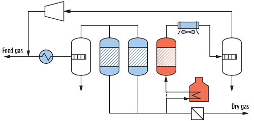
An adsorption unit used for water removal is called a dehydration unit (DHU). A DHU often consists of two or more vessels, filled with molecular sieves, that adsorb water during an adsorption period and are subsequently regenerated using a heated stream of treated gas. A sketch of a typical molecular sieve DHU is shown in Fig. 1.
 |
|
Fig. 1. Sketch of a typical molecular sieve DHU. |
The high temperature during regeneration causes water to desorb from the molecular sieve, a process called temperature swing adsorption (TSA). Although TSA is a discontinuous process, the overall DHU behaves like a continuous process because one or more vessels are always in adsorption mode, while another vessel(s) is in regeneration mode.
In a typical DHU, the regeneration gas used is a side (slip) stream of the product stream (typically approximately 10%). Downstream of the adsorber vessel, the wet regeneration gas is cooled, and water is condensed and subsequently removed in a knockout (KO) drum. When a molecular sieve unit is used for dehydration, it is possible to send the regeneration gas back to the feed after compression is performed to negate the pressure drop. Sending the regeneration gas back to the feed minimizes valuable product losses. Note: This type of lineup is possible only for DHUs designed for water removal, as knocking out the water in the regeneration KO drum provides a “drain” from the system. Components that cannot be removed from the loop in such a manner (e.g., sulfur species, such as mercaptans) will build up in the regeneration gas loop. Consequently, in such a lineup, the regeneration gas must first be treated by an appropriate absorption unit before it can be reinjected in the feed gas.
Providing a cost-effective and reliable design, as well as optimizing the performance of the DHU, require a detailed understanding of the DHU’s operation, as discussed in the following sections.
Basic design rules and operational requirements. As mentioned previously, an adsorption unit is a discontinuous process, since adsorption is essentially a batch process. One of the most important design parameters of an adsorption vessel is the available water uptake capacity of the molecular sieve bed. However, a few factors make this important design parameter less straightforward.
In adsorption, gas usually flows from top to bottom. During the adsorption period, the amount of water that can be adsorbed on the molecular sieve is dictated by both the capacity that can be reached in the limit of reaching equilibrium, and the capacity that results from the competition between adsorption kinetics and the flow of gas past a molecular sieve pellet.
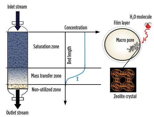
In the adsorbing bed, two zones can be identified. The capacity-limited portion is situated at the top. It is saturated with water under the feed conditions of temperature, pressure and water concentration, and is referred to as the saturation zone (SZ). The part of the bed below the SZ that is engaged in dehydrating the gas from feed water concentration (wet) to effluent water concentration (dry) is called the mass-transfer zone (MTZ) (Fig. 2). During adsorption, the MTZ migrates from the top of the bed to the bottom of the bed, thereby lengthening the SZ. Once the MTZ leaves the bed, breakthrough occurs and the bed must be taken offline for regeneration.3,4,5
 |
|
Fig. 2. Mass transfer zone in an adsorption vessel. |
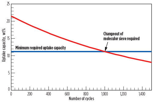
Another important parameter to take into account is that the capacity of the adsorbent decreases over time as a function of the number of regeneration cycles; therefore, end-of-run (EOR) capacity must be used when considering the required amount of adsorbent. When the capacity of the adsorbent falls below the level where all water in the feed can be adsorbed during the minimum adsorption time, then the adsorbent must be replaced (Fig. 3).
 |
|
Fig. 3. Typical deactivation and molecular sieve changeout profile. |
Another important design parameter is the ability to predict the rate of deactivation. It is important to understand the main factors contributing to the deactivation of the molecular sieve. In general, these contributing factors are consequences of the thermal regeneration process.6
During regeneration of the water-saturated molecular sieve, hot dry gas is passed upward through the molecular sieve bed, and water desorbs. If the beginning of the regeneration cycle were started with dry gas at the maximum temperature, then water would first desorb from the bottom portion of the bed, using much of the heat of the gas. Subsequently, water that desorbed from the bottom portion of the bed would be carried to the top portion, which would not yet have been heated by the regeneration gas. The top portion of the bed would still be cold and saturated with water, so the desorbed water from the bottom portion of the bed could condense to form liquid water. The formation of hot liquid water in the bed could cause the clay binder of the molecular sieve to dissolve, subsequently forming cake during the regeneration step.2,5–12
Caking due to hot liquid water formation during regeneration can be avoided by using a well-designed heating profile during the regeneration cycle. If the temperature of the regeneration gas entering the bed is slowly increased, then the top portion of the bed can be preheated before much water desorbs from the bottom portion of the bed. Preheating the top portion of the bed prevents condensation of liquid water when the water from the bottom portion of the bed is finally desorbed. If a non-ideal temperature profile is used during regeneration, then degradation of the molecular sieve might still occur without the formation of a large solid cake.
The characteristics of the temperature profile required to avoid liquid water formation depend on a number of factors. The flowrate and composition of the regeneration gas dictate how much heat is delivered to the molecular sieve bed. The diameter and materials of the vessel determine how much heat is transferred to the vessel, and at what rate, as opposed to the amount of heat that is transferred to the molecular sieve. Furthermore, the amount of water adsorbed on the molecular sieve, taking into account the MTZ, dictates the gas-phase concentration profile of water moving upward through the bed.
Another form of molecular sieve deactivation is through coke deposition on the molecular sieve. If the feed to the unit is heavy, then the heavier hydrocarbons can be adsorbed onto the molecular sieve binder during adsorption. A portion of the hydrocarbons will be desorbed during regeneration, but the residual will remain on the binder, decompose and irreversibly form coke under hot regeneration conditions, which can lead to pore blocking that results in a lower water uptake capacity.
The least contributing factor is the effect that continual thermal cycling has on the molecular sieve. Some thermal degradation, and the subsequent loss in water removal capacity of the molecular sieve, will occur. The extent of this degradation and loss is dependent on the thermal stability of the molecular sieve. The regeneration process also causes degradation of the binder material. The expansion and contraction experienced during thermal swings lead to dust production and an increase in pressure drop that is detrimental to LNG production.
As the capacity of an adsorbent is limited and the vessels become more expensive as the diameter (i.e., the required wall thickness) increases, a significant economic driver exists to keep the vessels as small as possible. One way to achieve this is to operate at high pressures (typically 60 bara), as the mass flow to be treated is then compressed in a smaller volume. Another way is to reduce the amount of water deposited on the bed by cooling the feed stream and knocking out excess water in the feed KO drum. The temperature reduction is limited by the hydrate formation temperature, and the operating temperature is chosen for safe operation above that temperature.1 Another reason to operate at a low temperature is that the uptake capacity of the molecular sieve is higher.
Not yet discussed is the type of molecular sieve to be used.2,5,7,13 For dehydration, and especially for molecular sieve units used in LNG application, type 4A is used. As previously mentioned, a molecular sieve is composed of a zeolite and a binder, typically clay. The binder is used as a glue to strengthen the particles. The type of zeolite typically used for dehydration is the Linde Type A (LTA). A refers to Angstrom, indicating the diameter of the zeolite channels where the water is adsorbed; i.e., 4A refers to a zeolite with a channel diameter of 4 Angstrom. Apart from 4A, 3A LTA and 5A LTA sieves are also used. In these sieves, the type of cation determines the channel diameter (K+ for 3A, Na+ for 4A and Ca2+ for 5A).
The effectiveness of zeolites for water removal is based on two important characteristics:
- The channel diameter acting as a filter, which limits the number of species that can co-adsorb
- The polar environment created in the channels, which creates an environment in which preferentially polar molecules are adsorbed.
Water is the molecule that is adsorbed the strongest; consequently, water will displace all other adsorbed molecules. For LNG applications, a 4A sieve is more stable and has higher water uptake capacity than a 3A sieve, and less coadsorption will occur compared to a 5A sieve. However, in gas processing plants that process pipeline gas, a 3A sieve is typically used. The reason is that if methanol is added to the feed gas to prevent hydrate formation, it will pass the 3A sieve bed, since methanol does not fit into the pores. The methanol can be recovered downstream of the beds in the part of the lineup where heavier hydrocarbons (e.g., propane and butane) are separated from the natural gas. Furthermore, coadsorption of methanol on larger-pore sieves will adversely affect the effectiveness of the molecular sieve with regard to water removal.
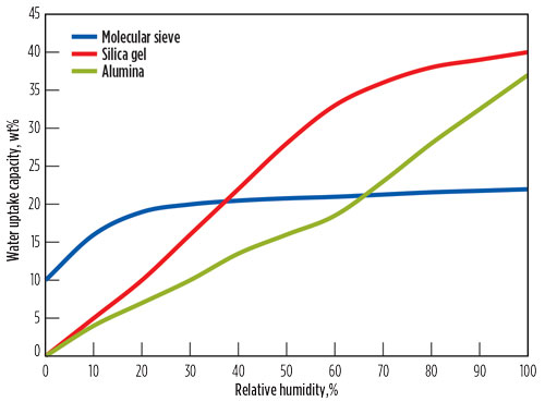
The question of why molecular sieves are best suited for deep dehydration is illustrated in Fig. 4, where typical isotherms of adsorbents used for dehydration are shown.2,13,14 Although molecular sieves have a lower saturation capacity than alumina or silica gel, that capacity is much less dependent on the partial water pressure, which enables deeper specifications to be reached (< 0.1 ppmv H2O).
 |
|
Fig. 4. Typical isotherms of some adsorbents. |
This characteristic also results in a shorter MTZ, enabling more efficient use of the adsorbent bed. In this context, it should be noted that the length of the MTZ is also determined by the particle size. For that reason, molecular sieve beds are typically layered, with the larger particles (e.g., 1⁄8 in.) used in the top layers to minimize the overall bed pressure drop and the smaller particles (e.g., 1⁄16 in.) in the bottom layer.
Another reason to select molecular sieves for dehydration is that the water uptake capacity is less dependent on feed temperature in comparison to silica gel and alumina. Furthermore, in contrast to molecular sieves, alumina and silica gel are large-pore adsorbents and, therefore, more co-adsorption of hydrocarbons will occur. Similar to molecular sieves, water will displace the coadsorbed components since it adsorbs stronger to the adsorbent; however, co-adsorption will also influence the length of the MTZ. More importantly, when regenerating the adsorbents, these co-adsorbed species will leave the adsorbent as peaks. If the regeneration gas must be treated, then the treating unit must be sized such that it can process these peaks. This factor significantly increases the cost of such a unit.
The majority of topics discussed to this point are related to the chemistry involved in the process. However, other factors are equally important from a design point of view—more specifically, those determined by process engineering and economics.
In gas processing, a plant is typically designed and operated with a single purpose: to process natural gas so that the maximum amount of condensates can be recovered, and so that produced gas adheres to certain specifications. In general, the gas is produced for use in the natural gas grid or for liquefaction and transport to markets. The economic aim for such a lineup is to minimize the number and size of vessels, process steps and plot space. From an engineer’s point of view, that means safely pushing as much mass flow as possible through the smallest possible vessels. The total amount of gas and liquids to be processed is the economic basis of such a project. The design of the vessel must adhere to maximum flow and minimum flow criteria.
In gas phase systems, gas flow during adsorption moves downward to prevent fluidization of the bed under abnormal flow conditions. The diameter of the bed can be calculated once the superficial velocity is determined.1 The superficial velocity must be chosen so that the following criteria are met:
- The maximum velocity is determined by a maximum absolute gas velocity criterion that is typically around 0.2 m/s. In LNG/NGL extraction plants, there is a significant price on each unit of pressure drop (∆P) consumed. In such cases, it is common practice to limit the ∆P to < 60 kPa. The end-of-run pressure drop is typically twice this value. For other cases, the designer should evaluate the economic benefit of a larger pressure drop. Note: A large pressure drop will also increase the risk of retrograde condensation occurring.
- The minimum velocity is determined by several criteria. The pressure drop per unit length should be at least 230 Pa/m.1 This criterion will ensure that the pressure drop over the packed bed determines the gas flow, and that proper radial distribution of the flow is promoted. When the gas flow is divided into more than one bed during adsorption without individual flow control, it is desirable to have an “appreciable” ∆P to ensure equitable flow distribution (i.e., ∆P > 20 kPa). The minimum velocity is also limited by turbulent flow considerations, as expressed by the Reynolds number (e.g., Re ≥ 40 > 100) Note: Molecular sieve vendors do not always apply this criterion in the way it is formulated.
Some of these criteria are of importance to the main process flow, but they should also apply to the regeneration gas flow (in each stage of the temperature profile), which, for gas processing vessels, is typically upflow. Apart from these criteria, the regeneration gas flow must carry enough heat into the system to ensure that the beds are properly regenerated. Sufficient flow will ensure the stripping efficiency of the desorbed molecules, and the beds should be cooled within the time frame available.
Within these constraints, the objective is to secure a regeneration gas flow that is as small as possible—typically around 10% of the feed flow. Particularly when the regeneration gas is sent back to the feed, a minimum regeneration flow ensures minimum-size regeneration loop equipment and, even more importantly, helps reduce the size of the adsorber vessels. For lineups such as those shown in Fig. 1, the flow passing through the main process line units is the feed flow combined with the regeneration flow. As the regeneration flow is upflow, another important design constraint is to avoid fluidization of the bed.
The length (L) and diameter (D) of the beds are limited mainly for practical and economic reasons. One important limitation is the strength of the adsorbent particles, especially those at the bottom of the bed. These should be sufficiently strong to withstand the sum of the pressure drop over the bed, the weight of the bed above them when saturated with water, and the weight of the pressurized gas.
A more practical observation is that bed heights of more than 10 m are rarely observed. In such cases, the adsorber vessels tend to become the highest units at the site. Minimizing the diameter is an important economic constraint. A larger diameter is associated with greater wall thickness, which will increase the cost of the vessel. A rule of thumb that is often applied in vessel sizing is the L/D > 2 criterion. With a lower ratio, the result is often a so-called “pancake reactor.” In this type of reactor construction, most of the steel (i.e., cost) used for the vessel ends up in the top and bottom domes, where the curvature is more or less fixed.
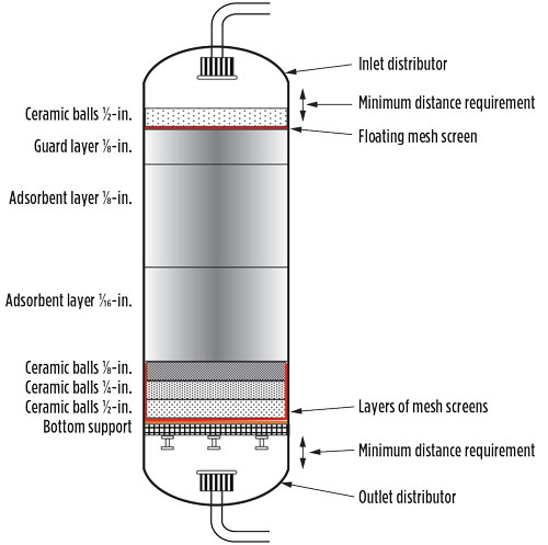
A sketch of a typical adsorber vessel is shown in Fig. 5.7 A certain distance between the bottom of the inlet distributor and the top of the bed is required to ensure pressure and flow equalization. The flow is reversed during regeneration, and the same requirement applies to the bottom portion of the bed. A careful observer will notice that the difference in size between the ceramic ball layers never exceeds a factor of 2. This ratio is preserved to lower the probability that smaller particles will migrate between larger particles.
 |
|
Fig. 5. Sketch of a regenerable adsorber vessel. Note: Sketch is not to scale. Dump ports, manholes and probes are not included. |
In a worst-case scenario, such migration could lead to a small depression in the top of the bed, thereby creating a preferential flow path due to the lower pressure difference in the part of the bed referred to as a “channel.” If a channel is created in a bed, then the mole sieve in and around that path will be depleted much more quickly than the surroundings, since a larger part of the flow moves through it. This depletion will ultimately result in an early breakthrough of the bed.
As the capacity of a molecular sieve bed is limited and declines as a function of the number of regeneration cycles, an important design criterion is the required lifetime (i.e., how long the bed must last before a changeout of the inventory is required). That depends somewhat on the application; in general, molecular sieve beds are changed out during a major shutdown of the plant. Major turnarounds are planned every 2 yr–3 yr, as various pieces of kit require maintenance.
For an LNG site, turbine and compressor maintenance needs determine when a major shutdown occurs. For most sites, the timing is every 4 yr. Although this timing provides the process engineer with a time frame for designing a molecular sieve bed, a translation to the number of cycles that fits into that period is required because the beds must retain sufficient water uptake capacity at the end of the 4-yr period.
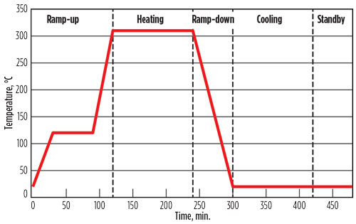
An adsorption cycle comprises several steps. The major steps are adsorption and regeneration, whereby the regeneration step can be subdivided in heating, cooling and standby steps.2,5,9,12,15 The highest temperature to which the molecular sieve can be exposed during regeneration is determined by the thermal stability of the molecular sieve. For a 4A sieve, the temperature limit is 320°C.
Although regeneration can take place at lower temperatures, the consequence is that more water will remain on the molecular sieve, thereby reducing the effective water uptake capacity. A typical regeneration profile is shown in Fig. 6. The step during ramp-up is inserted to prevent an overly rapid heating, which can result in hot water formation.
 |
|
Fig. 6. Typical regeneration temperature profile. |
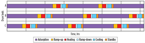
A typical adsorption time is 16 hr. Although TSA is a discontinuous process, the overall DHU behaves like a continuous process because one or more vessels are in adsorption mode, while another vessel(s) is in regeneration mode. Consequently, there is a limit to the time available for regeneration. With an adsorption time of 16 hr, in a 1+1 lineup, 16 hr are available for regeneration (cycle time is 32 hr), while in a 2+1 lineup (Fig. 1), only 8 hr are available for regeneration (cycle time is 24 hr). A cycle time sequence for a 2+1 lineup is depicted in Fig. 7.
 |
|
Fig. 7. Cycle time sequence. |
The timing in a cycle time sequence is critical, as the transfer of beds from adsorption to regeneration must happen flawlessly. A mistake in the timing could result where one bed is coming out of the adsorption step while the bed being regenerated is still in the heating step, thereby creating a forced shutdown. Most sites work with fixed cycle times, which means that when the beds are “fresh,” excess capacity is available as the bed heights are designed for end-of-run conditions.
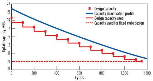
It is possible to minimize this effect by applying a “variable cycling” design, where the cycle time is adjusted at regular intervals in such a manner that these changes roughly follow the deactivation profile shown in Fig. 8. In this way, smaller beds can be designed, or the lifetime of the beds can be somewhat extended by reducing the overall number of cycles during troubleshooting or debottlenecking, thereby slowing the deactivation rate of the adsorbent.
 |
|
Fig. 8. Graphic presentation of variable cycling. |
As a consequence of this mode of operation, the minimum required capacity illustrated in Fig. 8 is essentially determined by the minimum time needed for regeneration—i.e., the fastest time heating and cooling can be achieved while ensuring that the beds are fully regenerated.
Additional comments. Only the main design elements were discussed for a fairly typical molecular sieve unit. Not discussed are the various other permutations possible—for example, the number of vessels deployed (e.g., 1+1, 3+1, 3+2, 4+2 lineups), the choice and the routing of the regeneration gas, regeneration gas heating options, regeneration at lower pressures, external or internal insulation of the vessels, etc. Although these options will influence vessel sizing and the total cost of the unit, the basic design elements discussed here will be the same.
Takeaway. The main design elements required for designing and operating a molecular sieve DHU are well understood. When taking these elements into account, it is possible to design molecular sieve units that are reliable, that deliver on specification and with required lifetime, and that require relatively little operational attention. GP
Literature cited
- Mokhatab, S., W. A. Poe and J. Y. Mak, Handbook of Natural Gas Transmission and Processing, 3rd Ed., Gulf Professional Publishing, Burlington, Massachusetts, 2015.
- De Bruijn, J. N. H., M. A. Huffmaster, J. M. van de Graaf, P. F. A. van Grinsven and H. Grootjans, “Maximizing molecular sieve performance in natural gas processing,” GPA Annual Convention, Dallas, Texas, March 11–13, 2002.
- Carlsson, A. F., J. B. Rajani and A. J. Kodde, “Finding the fountain of youth for a molecular sieve dehydration unit,” GPA Europe Annual Conference, Provence, France, September 22–24, 2004.
- Hawes, P., “Molecular sieves in natural gas processing,” GPA Europe Young Professional Training Day, Manchester, UK, February 11, 2016.
- Terrigeol, A., “Molecular sieves in gas processing: Effects and consequences by contaminants,” GPA Europe Annual Conference, Berlin, Germany, May 24–25, 2012.
- Meyer, P., “Molecular sieves troubleshooting,” GPA Europe Annual Conference, Lisbon, Portugal, September 22–24, 2010.
- Herold, R., “Use analytical tools to investigate LNG molecular sieve underperformance,” Gas Processing, April 2015.
- Pack, B. and A. Shackleford, “Gas conditioning failures show need for design scrutiny,” Oil & Gas Journal, Vol. 111, Iss. 5, May 2013.
- Meyer, P., “Easy and sophisticated debottlenecking of molecular sieve plants,” Hydrocarbon World, Vol. 5, Iss. 1, 2010.
- Meyer, P., “Cost reduction using high-density molecular sieves,” GPA Annual Convention, San Antonio, Texas, April 3–6, 2011.
 |
Ruud H. M. Herold was formerly a Senior Process Engineer at Shell Global Solutions International BV in Amsterdam, The Netherlands. He joined the company in 1986 and began working in the gas processing group in 2001, where he specialized in adsorption and catalytic processes used in gas and liquids treating. Mr. Herold holds an MSc degree in chemical engineering from the University of Amsterdam.
 |
Saeid Mokhatab is one of the most recognizable names in the natural gas processing industry. He has been actively involved in the design and operation of several gas processing plants around the world, and has contributed to gas processing technology improvements through 300 technical papers and two well-known handbooks (published by Elsevier in the US). He founded Elsevier’s Journal of Natural Gas Science & Engineering, and has given invited lectures on gas processing technologies worldwide. As a result of his work, Mr. Mokhatab has received a number of international awards and medals, and has been listed in prestigious biographical directories.


Comments