
Integrally geared MR compressors reduce CAPEX and boost efficiency of small-scale LNG
T. Patel, Atlas Copco Gas and Process Division, Houston, Texas
While lower natural gas prices have created challenges for large-scale LNG liquefaction plants, they are creating opportunities for the industry’s small- to mid-sized counterparts. From small-scale LNG (SSLNG) projects in the US spurred on by shale-gas development to early adopters in Europe and Asia, many operators are taking advantage of the benefits of going small-scale.
SSLNG applications have expanded throughout fuel markets, ranging from transportation hubs for long-haul vehicles, buses, trains and shipping fleets to remote commercial and residential heating networks. Other applications include cost-effective, stand-alone power generation in remote locations, peakshaving plants and even virtual pipeline systems to deliver energy to off-grid areas. Since the gas volume is being reduced by 600 times, SSLNG poses an attractive alternative to CNG, as it enables less frequent refueling.
Yet, just as SSLNG is helping expand the options for LNG’s availability and scope beyond what the larger counterparts can provide, it is important to understand that small-scale projects have a different set of technical and logistical requirements. Quick deployment, scalability, redeployment capability and fast response to market demand are important factors. Often, the technologies used in larger plants cannot be efficiently scaled down, including the compressors running the refrigeration cycle.
Integrally geared centrifugal compressors (IGCs) are more economically attractive, offering both a lower initial investment and lower operating costs. The small size of IGCs and their ability to accommodate interstage cooling and greater process control allow operators to make full use of agile plant deployment and to more efficiently run the plant once it becomes operational. With the added potential of standardizing compressor aerodynamics due to the similar molecular weight of available mixed refrigerant (MR) mixtures, the benefits become stacked in favor of IGCs.
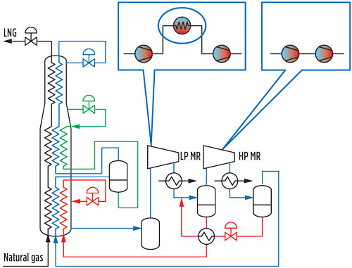
Cycle options and compressor solution for MR. The most common liquefaction process for SSLNG liquefaction trains with a capacity of less than 1 MMtpy is the single mixed refrigerant (SMR) cycle. SMR uses various hydrocarbons (ethylene, methane and i-butane and/or i-pentane) in place of the pure hydrocarbon refrigerants used in the discrete cooling steps of a cascade refrigerant cycle. In basic terms, SMRs condense a hydrocarbon gas mixture to a liquid, and then use cooling through its vaporization to chill natural gas close to its boiling point of –162°C (–260°F). The final phase change into LNG is often achieved with a valve utilizing the Joule-Thomson effect.
Several proprietary SMR processes are available on the market. These processes typically employ a single-pressure MR cycle (i.e., the refrigerant is compressed to its highest pressure before being sent to a series of condensers and separators, and finally to the heat exchanger to chill the LNG). To boost efficiency, some SMR processes vaporize the MR in two steps (a high-pressure and a low-pressure stage), which can be driven by either two compressors or, preferably, by a single compressor with two separate stage groupings.
Depending on the specific process, ammonia and propane precooling and/or subcooling may be added, along with fractionation of the refrigerant early in the cycle (Fig. 1). Choosing which process is right for a specific plant usually requires a balance between the initial capital expenditure (CAPEX) and long-term efficiency savings—in short, a lifecycle cost analysis. “Hot-to-cold” startup time, particularly for plants running intermittently, and targeted capacity may also be deciding factors.
 |
|
Fig. 1. Example of a process flow with interstage gas cooling. |
Although some variety exists in the application of the SMR concept, from the standpoint of compression technology the specific processes are quite similar. They utilize a mixed hydrocarbon refrigerant with a molecular mass ranging from 32 kg/mol–37 kg/kmol.
The somewhat narrow range of compression requirements allows for standardization of the compressor’s aerodynamic design. Since impeller blade geometry and other aerodynamics do not need to be fully customized to each process, CAPEX and manufacturing time is reduced; the compressor is delivered for commissioning faster, at a lower initial investment. Considering that the liquefaction process can account for upwards of 50% of the total project costs, lower investment costs for the compressor can go a long way toward plant viability.
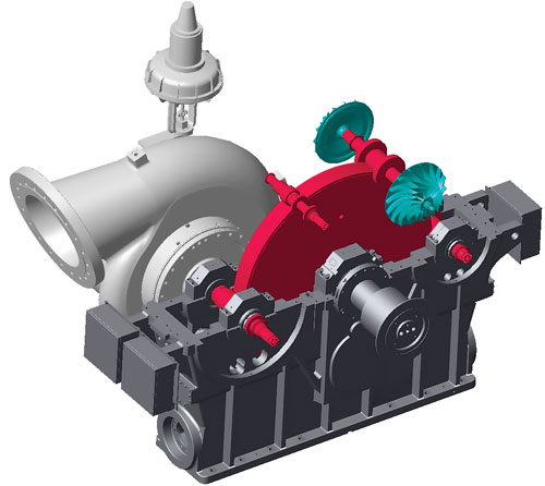
Energy savings through integral-gear technology. Integral-gear technology is based on a central (integral) gearbox, inside which a main bull gear drives several separate pinions (Fig. 2). These pinions supply rotational power to compression stages that are paired sequentially into stage groups of two.
 |
|
Fig. 2. Integrally geared compressor gearbox.a |
One of the primary benefits of IGCs is the ability to set the optimal speed for each two-stage grouping during the design process. This optimal speed is, in turn, determined by the rotor and aerodynamic properties of the impeller, diffuser and volute—the parts of the machine that compress the gas. This speed is translated into the gear ratio between the bull gear and the corresponding pinion for its stage group.
This type of stage optimization is not possible on a single-shaft machine, where all stages are arranged into one, or sometimes two, housings and are run off the main shaft at the same speed. Instead, a single-shaft compressor relies on a compromise: The design attempts to set as many stages as close to their respective optimal speeds as possible. However, the discrepancies between the optimal and actual rotational speed at each stage are compounded, leading to reduced efficiency for the entire compressor; i.e., more energy is required to drive the machine, requiring more power.
As an additional benefit, the improved aerodynamics that IGCs can obtain at each stage, further enhanced by optional intercooling, typically translate into higher per-stage pressure ratios. The result is that fewer compression stages are necessary to reach a target outlet pressure. This means lower material and manufacturing costs, which, in turn, help keep the price tag of an IGC below a comparable single-shaft, inline compressor.
In general, compressors requiring gas or electric drives delivering up to 25 MW (33,000 hp) are good fits for integral-gear technology. In a reference case study, a non-intercooler-equipped MR compressor delivering a mass flow of 61,824 Nm3/hr (36,388 ft3/m) for a refrigerant with a molecular weight of 36.223 kg/kmol saw a power savings of 3.2% vs. a base single-shaft compressor design when running at full availability. At the competitive local electricity price of roughly $0.06/kWh, this resulted in a cost savings of nearly $80,000/yr.
Boosting efficiency with intercooling. In addition to stage-speed optimization, an integral-gear compressor design also supports intercooling, which is optionally installed between the stages of the MR compressor. By comparison, intercooling is more complicated and costly in a single-shaft inline compressor, requiring that the housing be divided into sections.
Intercooling is essential for high isentropic efficiency, a measure of the deviation of the actual compression process from an ideal, theoretical compression process. The temperature of a gas rises when it is put under pressure, which requires an increased amount of work—and thus, more energy—in the next compression stage to further compress the gas. By cooling the gas between stages, the compression more closely mirrors an ideal isentropic process because fluid friction is reduced.
In the case study, intercooling increased efficiency by 6% and contributed to a total power savings of around 9.3%. Running at 100% availability, this could save the equivalent of $220,000/yr in power costs.
IGVs/DGVs for improved process control. In cases where air-cooled condensers are used, when the ambient temperature rises, the refrigerant condensing temperature will also rise as pressure increases in the cycle. To maintain the same level of cooling, the system will require increased flow at higher pressures.
To effectively control mass flow and power consumption, two control types are incorporated into IGCs: either variable inlet guide vanes (IGVs) or variable diffuser guide vanes (DGVs), according to process characteristics and specifications. For liquefaction trains that primarily operate at 80% capacity and higher (which is mostly the case for water-cooled condensers), IGVs provide excellent efficiency, helping regulate spikes and troughs in inlet pressure so that the compressor can deliver a constant mass flow.
For processes that see frequent startup and turndowns, and where high adjustability to fluctuations in LNG output is required, variable DGVs provide a great answer.
Further boosting process control, one MR compressora segregates its four stages into two groupings. This is particularly attractive for MR plants running processes that vaporize their refrigerants at two different levels of pressure (a high-pressure and a low-pressure stage). The segregation allows for each stage grouping to be independently controlled with IGVs and DGVs and for precise control when, for example, refrigeration must be adjusted to match increased or decreased LNG throughput.
Through aerodynamic enhancements such as IGVs and DGVs, overall compressor efficiency can routinely reach 82%–84%. When integral-gearing technology’s inherent efficiency gains are added to the savings that IGVs/DGVs and intercooling provide, then total energy savings reach 13%–14%.
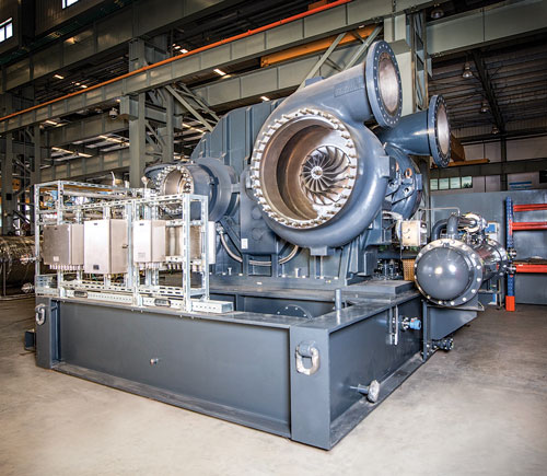
Additional features for MR applications. IGCs can build upon CAPEX, efficiency and process control benefits through their small size, convenient skid frame and tight sealing technology. Since integral-gear technology is the most compact compressor design in the industry, a four-stage MR compressor can fit onto a small skid measuring 10 m × 6 m (32 ft 9 in. × 19 ft 8 in.) (Fig. 3). The skid can accommodate a motor, instrumentation and peripherals like lube oil, seal support and control systems. Installation is simple and the skid can be easily accommodated into modular plant design for rapid setup and commissioning.
 |
|
Fig. 3. MR compressor.a Photo courtesy of Atlas Copco. |
Taking advantage of the gas-tight characteristics of dry gas seal technology and integrally geared compressor design, an MR compressor requires only a single external facing dry gas seal, which is standard. The option of using tandem dry face seals is also available; this allows for minimization of the seal leakage and improves machine reliability. Internal carbon ring and labyrinth seals minimize seal gas flow and prevent oil mist from entering the chamber. The seal design helps reduce MR leakage by up to 50%, saving approximately $17,000/yr in refrigerant top-ups, according to case study data.
IGCs offer comparably low maintenance requirements and a reliability of 99.8%. IGCs deliver continuous uptime and help simplify servicing. The gearbox casing allows for easy access when bearing replacements are needed, and also for effective monitoring of gears and pinions. Apart from this, maintenance does not differ greatly from standard single-shaft designs.
Takeaway. Integrally geared MR compressors deliver a more standardized, CAPEX-friendly compressor approach that takes into account the agile and flexible nature of the SSLNG landscape. GP
Notes
a. Atlas Copco’s mixed refrigerant compressor
 |
Tushar Patel is Business Development and Marketing Manager for Atlas Copco’s Gas and Process Division. With vast experience in global manufacturing, a BS degree in mechanical engineering and an MS degree in marketing management, he oversees global product marketing and business development for centrifugal and direct-driven turbocompressors, as well as expanders used in oil and gas and chemical/petrochemical processes, industrial gases and power generation.


Comments