
Develop successful nearshore FLNG solutions—Part 2: Natural gas liquefaction
S. Mokhatab, Gas Processing Consultant, Dartmouth, Nova Scotia, Canada; and S. Basi and P. Hunter, KBR, London, UK
Nearshore small- to mid-scale (0.5 MMtpy–2.5 MMtpy) FLNG production technology, which is viable for monetizing nearshore gas fields or converting pipeline-quality gas into LNG, provides another push to the FLNG market. As such, there is great interest in developing successful solutions for nearshore FLNG projects that may have advantages over competing onshore projects.
Part 2 of this series discusses various natural gas liquefaction processes to allow a selection that best fits the needs of FLNG applications. In addition, this paper addresses some of the design considerations that can reduce capital costs, thereby improving the overall economics of nearshore FLNG projects.
FLNG DESIGN BACKGROUND
It is clear that the design criteria for an FLNG facility is quite different from a land-based LNG plant in terms of process safety, storage, compactness, design flexibility, sensitivity to motion and simplicity of operation. Sensitivity to motion, which can cause process upsets or mechanical failures for an open-ocean offshore FLNG facility, is a lesser concern for a nearshore FLNG located in a relatively calm marine environment.
Further protection for a nearshore FLNG vessel can be provided by breakwaters or by fixing the FLNG vessel to a gravity-base structure or jetty structure. When the FLNG vessel is located adjacent to the shoreline, referred to as at-shore FLNG, opportunities exist to decongest the topside design by locating some non-hazardous elements onshore.
A successful nearshore barge-mounted FLNG project requires a proven liquefaction technology that is safe, simple, easy to operate and maintain, flexible for variations in gas composition and turndown, scalable and efficient in terms of space and cost. A number of design factors must also be addressed, such as machinery configuration, heat exchanger type, and utility systems. Each FLNG facility must be tailored to site-specific conditions to determine the optimal nearshore FLNG plant configuration.
FLOATING LIQUEFACTION CYCLES
Three main types of refrigeration cycles (cascade, mixed refrigerant and turboexpander) have been proposed for FLNG applications. Based on a proven track record with onshore facilities, mixed refrigerant (MR) and turboexpander-based technologies have been qualified by numerous operating companies for FLNG applications.
Although the Conoco Phillips Optimized Cascade Process is proven in mid- to large-scale onshore service, it is being considered for offshore service only by the technology licensor. As a result, the ConocoPhillips Optimized Cascade process is not covered in detail in this review.
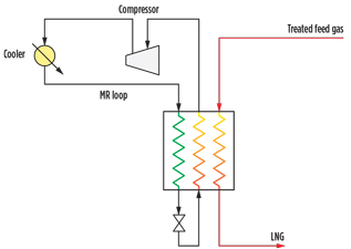
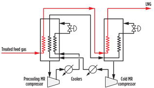
Mixed-refrigerant cycles. MR technology has been assessed for offshore liquefaction for both single-MR (SMR) and dual-MR (DMR) cycles. The SMR process (Fig. 1) benefits from operational simplicity and flexibility, as well as reduced equipment count; however, these benefits come at the expense of lower efficiency compared to the DMR cycle. With two refrigerant loops, the DMR cycle (Fig. 2) better matches the MR boiling curves to the overall feed gas condensation curve. The DMR process has been successfully applied to large-scale onshore LNG projects, while the SMR process is a proven solution for smaller onshore LNG facilities. Onshore SMR cycles are provided by Air Products and Chemicals Inc. (APCI), Linde and Black & Veatch, while DMR cycles are provided by APCI and Shell.
 |
|
Fig. 1. Typical process scheme of an SMR cycle. |
 |
|
Fig. 2. Typical process scheme of a DMR cycle. |
The APCI propane precooled single MR (C3-MR) process is a two-refrigerant loop process in which precooling is performed in multiple kettle-type heat exchangers with a propane refrigeration loop. This feature helps the process achieve a higher efficiency than the SMR process, due to the ability to better match the MR boiling curve to the feed gas condensation curve.
However, the large inventory of propane and the relatively large plot space that is required for the propane evaporators make the C3-MR process less attractive for FLNG projects than other cycles. The advantage of SMR and DMR technologies is the use of compact heat exchangers, which require significantly less topside footprint than the C3-MR technology.
Another variant of MR technology is the Mixed Fluid Cascade (MFC) process developed by Linde. This process has a similar efficiency to the DMR technology, but it utilizes three discrete MR refrigeration loops within two or three spiral-wound heat exchangers in series. This configuration increases the equipment count, congestion and hydrocarbon inventory, which is undesirable for small- to mid-scale FLNG facilities.
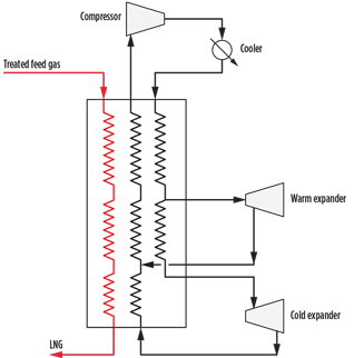
Expander cycles. Turboexpander refrigeration cycles, which use nitrogen (N2) as the refrigerant, have been widely used for small-scale LNG production (up to 0.8 MMtpy per train). While the single-expander cycle has relatively low efficiency, higher process efficiencies can be achieved by adding a second (Fig. 3) or third expander. Adding a precooling cycle, based on propane or other refrigerants (e.g., hydrofluorocarbons, carbon dioxide or methane), can improve overall efficiency and significantly increase throughput for a given barge size.
 |
|
Fig. 3. Typical process scheme of a dual-expander cycle. |
Increased FLNG facility complexity, reduced overall reliability and the need for increased refrigerant storage are potential disadvantages of adding a precooling refrigeration circuit. Many of the safety concerns can be negated by the selection of non-flammable refrigerants, and reliability concerns can be addressed by the use of parallel equipment or trains on larger FLNG facilities.
Several developments utilizing methane (sourced from the feed gas) and/or its combination with N2 have been proposed based on the dual-N2 expander cycle, but none of these schemes have been proven at small- to mid-scale capacities.
Process comparison. A comparison of liquefaction cycles is necessary to select an appropriate process for a given FLNG opportunity. Table 1 compares the liquefaction processes, taking into consideration typical criteria that influence the technical and commercial acceptance of small- to mid-scale FLNG projects.
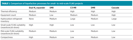
Of the processes compared in Table 1, the Cascade, C3-MR and DMR cycles are well-proven within large onshore LNG facilities. In adapting these technologies to a small- to mid-scale FLNG design, factors such as hydrocarbon inventory, equipment count and equipment selection must be addressed. None of these challenges are insurmountable or preclude the use of these technologies for FLNG; however, for a facility producing up to 2.5 MMtpy, other technologies may be more suitable.
The main disadvantage of the MR cycles (relative to the expander processes) is that they have a large hydrocarbon inventory at elevated pressure and require storage for significant quantities of liquid hydrocarbon refrigerants. These features raise additional safety concerns within a confined FLNG facility.
For all hydrocarbon-based refrigerant cycles, the sourcing of refrigerants may be an issue when processing lean feed gases (e.g., pipeline gas) that do not contain significant quantities of LPG. In these circumstances, the refrigerants can either be imported or extracted from the feed gas with the aid of a front-end NGL extraction scheme. However, this additional scheme will increase the weight, congestion, hydrocarbon inventory, cost and complexity of the FLNG topside.
The dual-N2 expander cycle provides many benefits for offshore and nearshore FLNG applications. A major advantage of using N2 as the cycle fluid is that it is inert, non-flammable and inherently safe. A process using inert refrigerant allows for compact equipment spacing on the FLNG vessel, as long as appropriate safeguards are taken to mitigate the asphyxiation risk in the event of a large leak. Using N2 eliminates the need for a C2/C3/C4 fractionation process for refrigerant makeup or for onboard refrigerant storage, since the N2 production needed for equipment purging and inerting can be augmented.
N2 is circulated in the gaseous phase at all points of the refrigeration cycle, so maldistribution in the heat exchangers is not a concern, unlike other refrigeration cycles that use multi-component refrigerants. As a result, the dual-N2 process performance is less sensitive to marine-induced motion.
The dual-N2 design is simple, and the reduced complexity will require less operator intervention than MR-based cycles. The control of specific temperatures is not as important for dual-N2 as with MR cycles, and the process is inherently stable and robust. Another important attribute of the dual-N2 cycle is the ability to quickly start up and shut down in a safe and controlled manner.
The dual-N2 and SMR cycles are considered more appropriate technologies for FLNG facilities at the smaller end of the capacity range, as the relative inefficiency of each cycle results in a low LNG-production-to-topside-area ratio.
DESIGN CONSIDERATIONS
In addition to designing a compact, flexible and energy-efficient gas liquefaction process, several design considerations must be properly addressed at the conceptual stage so that fundamental decisions can be made for developing a nearshore FLNG project. The following sections describe some of these considerations.
Liquefaction system. Key design requirements of the liquefaction system must be considered for the development of any FLNG project. This section will review main process equipment, train size and utility systems.
Main process equipment: Liquefaction heat exchangers. The main cryogenic heat exchanger, a critical piece of equipment in the liquefaction system, will be either a plate-fin heat exchanger (PFHE) or a spiral-wound heat exchanger (SWHE), depending on the liquefaction process selected.
PFHEs, often referred to as brazed-aluminum heat exchangers, consist of an aluminum core of alternating layers (passages) of corrugated fins. The layers are separated from each other by parting sheets. Each core will typically comprise no more than five streams. The design of each layer is optimized by varying fin type, fin height and pass geometry to maximize the heat transfer coefficient from streams in close proximity to each other. Layers are stacked within a core up to a maximum manufacturing limit. For liquefaction service, it is possible to manifold up to 6–8 cores together within a cold box.
PFHEs are specialized equipment manufactured by several vendors. The main advantages of PFHEs over SWHEs are their compactness, low equipment weight, small footprints, shorter lead times and lower capital costs. One disadvantage of PFHEs is that they are vulnerable to mechanical damage or damage from thermal shocks due to transient operating conditions, particularly in two-phase service. Exchangers subjected to repeated thermal excursions could fail, resulting in refrigerant or hydrocarbon leaks to atmosphere. This risk is partially mitigated by using PFHEs for single-phase, smaller-scale expander liquefaction cycles.
Distributing two-phase refrigerant across multiple cores could prove problematic for an FLNG facility, even with mild marine motion. The process must be operated to ensure a temperature difference between the different passes of no more than 50°F (28°C) to minimize thermal stress. Since PFHEs are contained within a self-supporting, insulated cold box with internal distribution headers, accessibility for in-place cleaning and repairing is difficult and time-consuming.
SWHEs are essentially vertical, helically wound shell-and-tube exchangers designed with a high heat transfer area, which allows them to operate with a larger temperature gradient. The advantages of an SWHE include its proven tolerance to thermal shocks (resulting from transient refrigerant/load imbalances) and containment of tube leaks within the exchanger shell. These features make the use of SWHEs an appropriate selection for MR cycles in FLNG applications. Compared to PFHEs, the SWHE is higher in capital cost, size and weight. The number of SWHE suppliers is limited, with each exchanger having a longer delivery time compared to a single, large cold box.
Technical design limits the available heat exchanger size for FLNG service. A single cold box typically can be designed to liquefy up to 0.75 MMtpy of LNG. However, a higher-train capacity would require multiple cold boxes to be grouped together in parallel to provide the necessary heat exchange area.
For FLNG, a single SWHE in SMR service can be designed to produce up to 1.5 MMtpy. In precooled MR service, it can be designed for up to 4 MMtpy of LNG. In general, PFHEs can be a good choice for small- to mid-scale floating liquefaction due to their lightweight, compact and highly efficient design for simultaneous heat exchange between multiple streams. For FLNG projects that are designed to utilize either PFHEs or SWHEs, the exchanger must be designed for the transient structural loads and vessel motions in addition to the thermal and hydraulic loads.
Both PFHEs and SWHEs are well proven within onshore LNG plants, and PFHEs have been successfully used offshore for many years. However, both types of exchangers are currently unproven in nearshore or offshore LNG service, with the first FLNG facility due to come onstream in 2016.
Compressor drivers. The refrigeration compressors in LNG plants are commonly driven by gas turbines. Electric power for LNG facilities is commonly provided by gas turbine generators. In some cases, electric motors or steam turbines have been used as compressor drivers. However, selecting the best driver for an FLNG facility is a challenging issue. Several parameters must be considered when addressing this issue, such as thermal efficiency, ease of operation, availability, economics, space and weight limitations, maintenance and safety considerations.
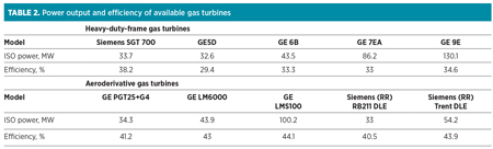
Heavy-duty industrial gas turbines, commonly used in onshore LNG plants, are difficult to deploy on an FLNG vessel as they are large in size, require significant maintenance periods and have limited speed variation capabilities. Aeroderivative gas turbines, which are lighter and more compact than heavy-duty frame industrial gas turbines, are better suited for floating installations, although they have been used only in LNG projects at power levels below 45 MW. Aeroderivative turbines have relatively high availability and reliability and are easy to service and maintain. In addition, they are more thermally efficient than industrial gas turbines (Table 2), resulting in lower fuel consumption and lower carbon emissions per unit of power.
Multiple aeroderivative gas turbines may be installed in parallel to achieve the required compression power demand for large LNG trains. With the many advantages of the aeroderivative turbines and the potential capital cost and energy savings over industrial machines, their use is being accepted for process drivers, particularly in smaller FLNG facilities.
Commercially available packages, in which aeroderivative turbines are coupled with centrifugal compressors, provide a new solution for FLNG applications. These packages feature faster installation, enhanced reliability and availability, ease of maintenance, and a reduced footprint and weight relative to frame machines. It should be noted that all gas turbine options have some inherent limitations that require detailed evaluation to determine the optimal selection for each FLNG facility.
Electric motor drive systems for the main refrigerant compressor(s) are more expensive than gas turbines, but they are an attractive option due to their higher availability, ease of operation and lower emissions. They may be an option for at-shore FLNG applications, as some of the larger electrical elements (e.g., switchgear, transformers) can be located off-barge. Some elements, however, must be located on the barge (e.g., variable-speed drive cabinets, harmonic filters).
In the event of importing electric power to a nearshore facility, motor drives will result in a shorter project schedule than for a project that includes a power generation unit. Electric motors of 65 MW have been used for an onshore LNG project, and 78-MW motors have been tested for a project under construction. While large electric motors offer high reliability, they also require a complex electrical system for startup and control. The economic feasibility of using large electric drives is dependent on the availability of a local, low-cost, reliable, high-voltage power supply.
Traditional steam turbine drivers are the best choice for overall reliability, availability and safety (no open ignition source). However, steam turbines necessitate more infrastructure (steam boilers, large heavy pipes, etc.) and include complex operations (requiring freshwater makeup and wastewater/chemical disposal). In addition, steam systems have a large footprint, more weight and the highest maintenance burden of the driver choices. The early onshore LNG facilities featured steam turbine drivers, but in the 1980s facilities switched to industrial gas turbine drivers, which proved to be more cost- and plot-efficient than steam turbines and supporting systems. As such, the steam turbine is not usually an economic driver selection for refrigeration compressors on an FLNG facility.
Turboexpanders. Today’s turboexpander technology can deliver robust designs with a small footprint and high performance (with typical isentropic efficiencies of nearly 90%) for FLNG applications. However, a limit exists on the size of current companders, meaning that multiple compander trains would be used if a large facility is required.
Liquefaction train size. For any type of LNG facility, the total facility capacity is often dictated by gas deliverability from dedicated gas fields or supply pipeline gas availability. The liquefaction train size is determined based on evaluating economies of scale for a large train vs. the availability benefits of multiple identical trains. For mid-scale FLNG, the facility may opt for either the single- or multi-train concept. In a multi-train concept, the facility has the capability to continue production when one of the trains is down for maintenance or an unexpected shutdown, while a single train may result in the lowest capital cost per unit of production.
Utility systems. For an at-shore FLNG facility, common utilities (i.e., refrigerant storage, amine storage, cooling water, seawater desalination, fuel gas, instrument air, N2 supply and storage tank systems) can be installed onshore and connected to support operation of the process units. No absolute definition is given of which utilities can be installed onshore; it is a matter of site-specific economics, regulations and other factors. However, a few utility systems should remain onboard to improve the safety, reliability and energy efficiency of the FLNG facility.
Cooling system. The interstage cooling for the refrigerant compressors on the nearshore FLNG facility can be provided by coastal seawater, freshwater or ambient air. For an at-shore FLNG facility, air cooler(s) can be installed onshore where space is available, but higher-approach temperatures to ambient air will result in lower process efficiency. Within FLNG, design safety concerns are paramount; therefore, only an indirect closed cooling water loop would be considered for onshore air cooling service.
The water cooling system can be an open or closed loop. In an open-loop system, a huge amount of seawater is drawn in, pumped directly through shell-and-tube heat exchangers (which are constructed of expensive, corrosion-resistant material, such as titanium) in the refrigeration systems, and then discharged back to the sea. Invariably, the nearshore FLNG facility will be located in shallow water close to shore, where warmer seawater will be encountered. This positioning will impact the process efficiency and adversely impact LNG production. Also, the water discharged into the sea must meet environmental requirements (in terms of maximum allowable return temperature, maximum temperature rise and residual chemical treatment) to minimize impact on ocean life nearshore.
In the closed-loop system, fresh cooling water is pumped through a closed circuit to the plate-and-frame heat exchangers (which are constructed of less-expensive carbon steel material), in which heat is rejected to seawater. This option allows for the possibility of controlling the inlet and outlet temperatures of the heat exchangers, thereby stabilizing the process. The introduction of an intermediate loop ultimately increases the process to seawater approaching temperature, with a consequential increase in the weight and loss of process efficiency.
Heating system. To improve the safety case of the FLNG facility, the heating system should not use fired heaters, if possible. As such, waste heat from gas turbine exhaust is recovered to provide process heating. The recovered heat is used mainly to meet the amine unit reboiler duty. Applying a heat-recovery steam-generation system on the exhausts of the gas turbines can also produce steam, which is used to generate additional electric power and to provide high-quality heat for regenerating molecular sieve beds. For operational simplicity, a heat transfer fluid is preferred to steam, as it avoids the operational complexity, large footprint, cost and weight of a steam generation system.
Power generation and emergency power. Although power to nearshore/at-shore FLNG facilities can be provided from the local power grid or an efficient combined-cycle power plant located onshore, the facility should include an onboard power-generation system to provide essential power to support the entire facility. The facility should also have its own diesel generators as a minimum to ensure safe shutdown, or a larger generator as a backup to normal operation.
Modularization. The modular building of the FLNG facility potentially reduces delivery time and moves costly site construction hours to fabrication yards, where cost and quality are best controlled. When practical, modules are designed up to 2,000 t to facilitate crane and transport availability. Larger modules (up to 4,000 t) have been installed on FLNG ships when the economic or schedule benefits were justified.
Potentially significant cost savings and advantages exist in modular design, but the application to LNG facilities has not yet been successful in reducing the overall cost. However, innovation, development, improved project management and redefinition of the workflow are necessary for more cost-effective modularization projects. These elements include offsite modularization at sites with lower labor costs and prefabrication of as many FLNG components as possible.
TAKEAWAY
Evaluating criteria for the commercial acceptance of FLNG projects has shown that the dual-N2 expander liquefaction process is an appropriate selection for both offshore and nearshore small-scale FLNG projects where layout area is limited. N2 expansion technology is a proven, simple, compact solution, and is undoubtedly the safest design among the well-known
refrigeration cycles.
The SMR process, in which a low equipment count gives a more compact design, is well-suited for small- to mid-scale nearshore FLNG with better efficiency than the dual-N2 cycle, but with a higher risk profile. SMR provides operational simplicity while maintaining high process efficiency and low operating costs. The viability of LNG projects can be improved by maximizing production, but FLNG has a finite limit on barge size and equipment size. Therefore, increased production can be realized by switching to a more efficient DMR liquefaction process, even though this will introduce additional hydrocarbon inventory and increase the equipment count.
Each FLNG facility will have unique aspects that require the process design to be tailored to achieve the optimum configuration. In addition to selecting the correct liquefaction capacity and technology, the execution aspects of the FLNG project (modularization strategy, construction philosophy, project execution and schedule) are also fundamental to achieving the overall objective of minimizing the cost/t of LNG.
End of series. Part 1 appeared in the July/August issue. GP
 |
Saeid Mokhatab is an internationally recognized gas processing consultant who has been actively involved in several large-scale gas field development projects, concentrating on design, precommissioning and startup of processing plants. He has presented on gas processing technologies worldwide and has authored or coauthored nearly 250 technical publications, including two well-known and frequently referenced Elsevier handbooks. He has held technical advisory positions for leading professional journals, societies and conferences in the field of gas processing, and has received a number of international awards in recognition of his outstanding work in the natural gas industry.
 |
Sukhpal Basi is a chief technical adviser with the LNG technology group at KBR in London, UK. Having started at M. W. Kellogg in 1995, he has worked on LNG studies, FEED and EPC projects across a range of onshore and offshore applications throughout his career.
 |
Philip Hunter is the senior vice president for global LNG, FLNG and GTL technology and development at KBR in London, UK. He has more than 38 years of experience in the LNG business, and is considered one of the world’s leading technical experts in the natural gas liquefaction area. He has been involved in different sectors of major LNG and gas processing projects, from feasibility study, technology management, conceptual design, and project engineering and construction, to plant commissioning, startup and operation. He has authored or coauthored several technical papers on LNG, and given numerous technical presentations at prestigious international conferences.


Comments