
Prevent hydrate formation with high-pressure deethanizer design
C. C. Chen and Y.-S. Liu, Wood Group Mustang, Houston, Texas
To produce high-purity ethane from a wet NGL feed, a high-pressure deethanizer design has been developed to prevent hydrate formation without using a dehydration unit. Formations of hydrates, which are crystalline solids composed of water and light hydrocarbon molecules, can result in issues with operation and safety. If high-purity ethane is desired as a product, then the deethanizer condenser and the top tray temperatures may be lower than the hydrate point. This can cause hydrate formation at these locations if the wet NGL is not dehydrated.
Conventional methods used to prevent hydrate formation include removing the content water in a glycol or a dry desiccant dehydration unit. Either way requires a complicated dehydration system. Here, a design method to eliminate the requirement of a dehydration unit is discussed. The deethanizer condenser temperature increases rapidly while the hydrate formation temperature increases slowly with the pressure. Using these characteristics, a high-purity ethane can be obtained by increasing the deethanizer pressure to force the condenser temperature to surpass the hydrate point. This way, the dehydration process is not required.
The economic analysis and the limitations of this approach are discussed in detail. This method has been used successfully in a commercial setting.
NGL fractionation design. Natural gas and water can form a crystalline solid compound commonly known as gas hydrate. The hydrocarbon gas molecules (e.g., methane, ethane, propane and carbon dioxide) are trapped in a rigid, cage-like lattice of water molecules.1
Gas hydrates can cause pipeline plugs, which lead to safety and operational issues in the oil and gas industries.2 Furthermore, gas hydrates can plug tower trays and valves, resulting in tower flooding.3 Gas hydrates can form in high-pressure, low-temperature conditions where free water is present. Therefore, the three existing methods to prevent and mitigate hydrate
formation are:
- Dehydration
- Maintaining an operating temperature higher than the hydrate formation temperature
- Operating at a pressure lower than the hydrate formation pressure.
In an NGL fractionation plant, a refrigerated deethanizer condenser is used to separate ethane from heavier components. If the NGL feed is wet or saturated with water, and if high-purity ethane is to be produced, then hydrates can form in the top section of the deethanizer and in the chilled deethanizer condenser, where the operating temperature may be lower than the hydrate formation temperature.
The conventional method of suppressing hydrate formation in the deethanizer system is to remove water content in the NGL feed using either dry desiccant beds or a glycol contactor.4 A better approach may be to eliminate the requirement of a dehydration unit by optimizing the operating conditions.
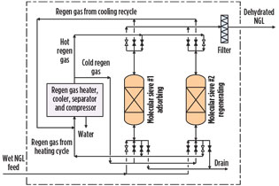
Conventional dehydration: Dry desiccant beds. Typically, molecular sieve or silica gel beds are used to dehydrate light liquid hydrocarbons, such as liquefied petroleum gas (LPG) or natural gas liquids (NGL). As shown in Fig. 1, a dry desiccant system is batch-operated and consists of adsorption and desorption (regeneration) beds with a complex switching valve arrangement.
 |
|
Fig. 1. Molecular sieve dehydration. |
The regeneration system includes a regeneration gas heater, regeneration gas cooler, regeneration gas separator, regeneration gas compressor and other miscellaneous items. The process of periodical switching between adsorption, heating and cooling cycles is complicated. However, it can be managed by an automatic timer control.
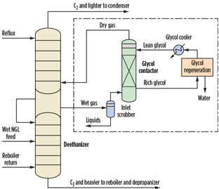
Glycol contactor. The use of a continuous-operated glycol dehydration unit is simpler than that of a dry desiccant unit. However, a glycol unit is commonly used for gas dehydration. To operate a glycol unit, a vapor stream is drawn from and returned to the deethanizer after it is dehydrated. This means that the deethanizer column requires an extra length for side vapor/liquid draws and returns (Fig. 2).
 |
|
Fig. 2. Deethanizer with glycol dehydration. |
Additionally, a dehydrated gas compressor or a side draw liquid return pump may be needed to compensate for the pressure drops in the draw piping, return piping and the glycol contactor. A glycol dehydration unit consists of a glycol contactor and a glycol regeneration system. The glycol regeneration system usually includes a minimum of a flash drum, a glycol reboiler/still column, a glycol/glycol exchanger, a high head lean glycol pump and a glycol cooler. Injecting stripping gas to help regeneration is also necessary, in some cases.
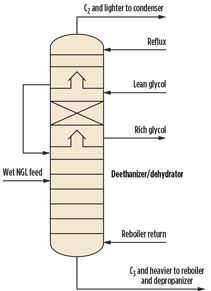
An alternative approach to dehydrating the vapor stream outside the deethanizer is to integrate the glycol contactor into the deethanizer (Fig. 3). The lean glycol dehydrates the hydrocarbon vapor leaving from the bottom chimney tray. The diameter of a standalone glycol contactor section is usually smaller than that of the deethanizer due to the minor amount of glycol used. However, in this alternative design, the diameter of the glycol contactor is typically the same as that of the deethanizer. These larger dimensions increase capital cost and may also reduce the mass-transfer effect caused by low loadings.
 |
|
Fig. 3. Alternative design of deethanizer |
High-operating-pressure approach without dehydration. The conventional dehydration methods described in the previous section utilize a complex dehydration unit that not only requires higher CAPEX, but also more plot for the additional equipment. To simplify the design, a high-pressure deethanizer that produces 95 LV% ethane from wet NGL without the need for a dehydration unit has been proposed.
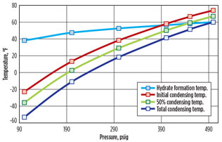
Typically, a deethanizer operates between 200 psig and 400 psig. Fig. 4 shows that when the deethanizer condenser is operated at low pressure, the condenser temperature is substantially lower than the hydrate formation temperature. In this case, gas hydrates will form if the stream is not dehydrated.
 |
|
Fig. 4. Deethanizer condensing temperatures vs. hydrate |
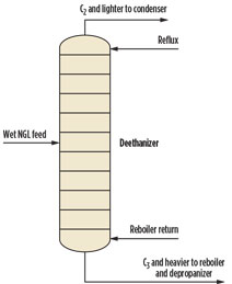
If pressure increases to approximately 390 psig, then the initial condensing temperature is roughly equal to the hydrate formation temperature. At approximately 490 psig, the overhead vapor can be totally condensed without forming gas hydrates. One engineering firma has capitalized on this principle by designing an alternative approach for producing 95 liquid volume percent (LV%) ethane from wet NGL by operating the bottom of the deethanizer near 500 psig (Fig. 5). This commercial-scale plant is in operation and has been running successfully for several years.
 |
|
Fig. 5. Deethanizer without dehydration. |
The drawback of using a high-pressure deethanizer is that a higher-pressure vessel requires a thicker wall, and a high-pressure component separation requires increased duties for the condenser and reboiler compared to a conventional design. The operating pressure is approximately 225 psi below the critical pressure at the deethanizer top and approximately 150 psi below the critical pressure at the deethanizer bottom; therefore, phase separation is still effective.
To demonstrate the selection of optimum operating conditions for different ethane purities, two case studies were conducted for a deethanizer processing 90 Mbpd of NGL containing 50% C2.
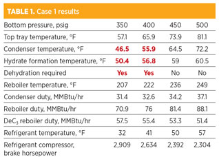
Case 1: Desired C2 product is 90 LV% C2. As shown in Table 1, the temperatures of the condenser at 350 psig and 400 psig are below the hydrate formation temperature. Therefore, NGL dehydration is required when the operating pressure of the deethanizer bottom is below approximately 410 psig.
Case 2: Desired C2 product is 95 LV% C2. As shown in Table 2, the temperatures of the condenser at 350 psig, 400 psig and 450 psig are below the hydrate formation temperatures. In addition, the temperatures of the top tray at 350 psig and 400 psig are also lower than the hydrate formation temperatures. Gas hydrates will form in the condenser at a pressure of 450 psig and lower. Similarly, gas hydrates will also form at the top tray inside the column at a pressure of 400 psig and lower.
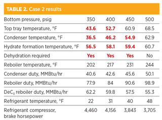
Comparing the results of Cases 1 and 2, higher C2 purity is associated with lower temperatures of the top tray and condenser at the same pressure. Therefore, the likelihood of gas hydrate formation increases. In Case 2, NGL dehydration is not required only when the deethanizer bottom pressure is near 500 psig.
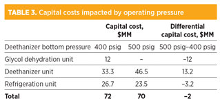
Economic analysis. For a high-pressure deethanizer with a bottom pressure of 500 psig, the capital cost of the deethanizer system is significantly higher. However, savings from not needing a dehydration system, as well as from the reduced capital cost of the smaller refrigeration unit using higher-temperature refrigerant, exceed the extra capital cost of the higher-pressure deethanizer system. Table 3 lists the estimated capital costs that are impacted by the operating pressure of the deethanizer. The total estimated capital cost of a high-pressure deethanizer system is approximately $2 MM lower than that of a conventional deethanizer system with a dehydration unit.
OPEX impacted by deethanizer operating pressure. The main increase of the utility costs for a higher-pressure deethanizer at 500 psig bottom pressure is due to its higher reboiler duty. Although the condenser duty is also increased, a higher-temperature refrigerant can be used for the warmer condenser. As a result, the hp of the refrigerant compressor is lower, as shown in Table 2. Since the outlet temperature of the deethanizer bottoms becomes higher, the duty of the downstream depropanizer reboiler is reduced.
Table 4 lists the estimated major differences of utility consumptions that are impacted by the operating pressure of the deethanizer. Some minor differences of utility consumptions are not included. For example, the hp change of the deethanizer reflux pump, flow change of cooling water, and glycol makeup cost are excluded in the OPEX comparison. The natural gas price for glycol regeneration was assumed to be $3/MMBtu, the electricity price for the refrigerant compressor was assumed to be $0.05/kWh, and the steam cost for reboilers was assumed to be $5/1,000 lb.
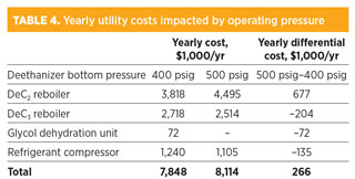
The total estimated yearly utility cost of a high-pressure deethanizer system is approximately $266,000/yr higher than that of a conventional deethanizer system with a glycol dehydration unit. Based on the estimated capital cost savings for the high-pressure design, the payback period of using the conventional system with a dehydration unit is approximately 7.5 years, which is marginal for the economic benefit consideration.
The economic analysis results are strongly influenced by individual equipment design assumptions, and the conclusions are impacted accordingly. As previously shown, the difference in capital investment for the two options is small, so the actual incremental economics may not be compelling or even exist. The main benefit of the high-pressure deethanizer design is the ability to eliminate the extra complexity introduced by a dehydration unit.
Takeaway. A high-pressure deethanizer process for producing high-purity ethane product without dehydration has been designed and proven to be a successful alternative in commercial operations, compared to conventional designs. This process eliminates the need for the installation of a complex molecular sieve or a glycol hydration unit, providing simplicity for both installation and operation. GP
Note
aWood Group Mustang developed the design discussed in this article.
Literature cited
1Gas Processors Suppliers Association, Engineering Data Book, 13th Ed., Tulsa, Oklahoma, 2012.
2Hammerschmidt, E. G., “Formation of gas hydrates in natural gas transmission lines,” Industrial Engineering & Chemistry, Vol. 26, Iss. 8, 1934.
3Kister, Henry Z., Distillation Troubleshooting, Wiley Publishing Inc., Hoboken, New Jersey, 2006.
4Kohl, A. L. and R. B. Nielsen, Gas Purification, 5th Ed., Gulf Publishing Company, Houston, Texas, 1997.
 |
Chyuan-Chung (C. C.) Chen is a process manager at Wood Group Mustang in Houston, Texas, and a registered professional engineer in Ohio. He has more than 40 years of engineering experience in oil and gas, gas processing, refining and other areas. Dr. Chen holds a BS degree from National Taiwan University and a PhD and MS degree from the University of Rochester, all in chemical engineering.
 |
Yen-Shan (Amy) Liu is a process engineer at Wood Group Mustang in Houston, Texas, and is a registered professional engineer in Louisiana. Prior to joining Wood Group Mustang, she was an assistant professor of chemical engineering at the University of Louisiana at Lafayette, and a senior consultant at ioMosaic Corp. Dr. Liu holds a BS degree from Mississippi State University and a PhD from Texas A&M University, both in chemical engineering
.


Comments