
Develop successful nearshore FLNG solutions—Part 1: Gas pretreatment strategies
S. Mokhatab, Consultant, Dartmouth, Nova Scotia, Canada
Movement has been seen in offshore floating liquefied natural gas (FLNG) developments. However, nearshore projects that utilize a barge-based floater located in a nearshore environment, and that also take advantage of onshore support, may be more secure than offshore alternatives. One reason for this scenario is that the offshore projects could face greater technical challenges and higher costs. As such, great interest exists in developing robust, reliable and innovative natural gas pretreatment and liquefaction solutions for nearshore, lower-cost FLNG projects.
At the nearshore FLNG facility, the need exists for a compact, flexible and energy-efficient pretreatment package to remove contaminants. This package must also deliver feed gas with the required specifications by the natural gas liquefaction unit to maintain continuous uptime of LNG production.
Part 1 of this article describes the appropriate processing technologies for designing a robust pretreatment section and shows how the integration of treatment technologies and expert know-how make a difference.
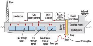
Gas pretreatment strategies. In a typical nearshore FLNG facility (Fig. 1), feed gas is transported via pipeline and flexible riser to the FLNG facility, where impurities are removed (in the gas pretreatment section) and the gas is liquefied before being stored onboard the facility.
 |
|
Fig. 1. Typical layout of a nearshore FLNG facility (modified |
Pursuant to LNG, other liquid products (LPG and condensate) will be stored and subsequently offloaded to marine carriers for delivery to market. While each facet of the nearshore FLNG production facility is important, the gas pretreatment section of the facility plays a critical role in treating the raw feed gas to meet final sulfur specifications and purity levels required by the natural gas liquefaction unit.
The specifications to be met include hydrogen sulfide (H2S) removal to under 4 ppmv, carbon dioxide (CO2) to below 50 ppmv, total sulfur to under 10 ppmv as S, water to less than 0.1 ppmv, and mercury (Hg) to the level of 0.01 µg/Nm3. Also, heavy hydrocarbons (HHCs) shall be removed to below freezing limits in cryogenic heat exchangers (typically in the range of 0.1 mol% for C6+ and a few ppm for aromatics). The general nitrogen (N2) specification for rundown LNG is 1 mol% maximum.
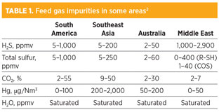
Table 1 shows feed gas impurities in various locations. Different locations require different gas treatment schemes. The following section briefly discusses the different technologies in treating sour feed gas to the natural gas liquefaction unit, and the technology in the removal of contaminants to meet environmental and emissions regulations and LNG feed gas specifications.
Acid gas removal. The acid gas removal unit (AGRU) mainly removes the acidic components, such as hydrogen sulfide (H2S) and carbon dioxide (CO2), from the feed gas stream. This process helps meet the sales gas H2S specification and avoid CO2 freezing (and subsequent blockages) in the cryogenic exchanger, respectively. It also removes some amount of carbonyl sulfide (COS), mercaptans (R-SH) and other organic sulfur species that contribute to sulfur emissions.
Three solvent absorption processes (chemical absorption, physical absorption and the mixed solvents) are commonly used for acid gas removal. These processes can also be used in FLNG production facilities. Most commonly, H2S and CO2 are removed from the natural gas feed stream in a chemical solvent unit utilizing an aqueous amine solvent.
With the exception of methyldiethanolamine (MDEA), amines are generally not selective and will remove both CO2 and H2S from the gas. When used in treating sour gases to meet the tight CO2 specification for LNG production, the activity of CO2 absorption is too slow with pure MDEA, which must be enhanced with a promoter (i.e., piperazine). In contrast, a feed gas with 10 mol% CO2–12 mol% CO2 can be handled by a promoted MDEA process.
The advantage of the amine technology is that the solubility of aromatics and heavy hydrocarbons in the aqueous solvent is low, resulting in lower hydrocarbon losses. However, the disadvantage is the high energy consumption for the regeneration of aqueous amine. Physical solvents, which can be applied advantageously when the partial pressure of the acid gas components in the feed gas is high (typically greater than 60 psi), will lower the energy consumption but will coabsorb more hydrocarbons. For this reason, physical solvents are generally suitable to treat lean gases.
When the need exists to treat rich gases, the NGLs must first be removed by chilling. As an alternative, the use of hybrid (mixed) chemical and physical solvents is beneficial, where they can be formulated to allow for complete CO2 removal, while achieving H2S removal comparable to alkanolamines.
In hybrid systems, mercaptans (R-SH) and other organic sulfur components, if present in the feed gas, can also be removed by the physical solvent portion. Generally, this option will result in an expensive design with a hydrocarbon coabsorption that is too large to be acceptable.3 In many cases, the optimum solution is the distribution of the mercaptans removal capabilities over the optimized mixed chemical-physical solvent in the AGRU and the molecular sieve unit (MSU). In this option, the regeneration of the MSU gas can be integrated with the AGRU using a shared regeneration system. The treated regeneration gas can then be recycled either to the inlet of the MSU or the inlet of the AGRU absorber.3
A number of processes (membranes, cryogenic fractionation and adsorption) are also available to remove H2S and CO2 from natural gas. Membrane separation, which offers several advantages compared to an amine unit (i.e., greater turndown capability, and reduced installation costs and plot space) is only suitable for bulk CO2 removal, where further treating with amine is required to meet H2S and CO2 specifications. The membranes require a suitable pretreatment system to remove particulates and to avoid liquid formation in the membranes. Improper pretreatment generally leads to performance decline rather than to complete nonperformance.
The main limitation of the membrane system is linked to the significant loss of hydrocarbons in the CO2 discharge. This constriction is partly due to the relatively large membrane surface area that would be required to reach a 50-ppm CO2 spec. Membrane systems perform well at reduced feed flowrates, but their performance drops when design flowrates are exceeded. Additional modules must, therefore, be added in parallel to accept higher flowrates. As a result, the membrane separation process does not realize the economies of scale as the flowrate is increased.
Cryogenic fractionation appears to offer a good prospect for removing CO2 and H2S from natural gas. However, this technology requires substantial energy to provide necessary refrigeration. It also requires pretreatment of feed gas to remove components with a freezing point above the operating temperature to avoid freezing of lines and blockages of process equipment.
Adsorbents for acid gas removal are generally limited to small gas streams operating at moderate pressures. For example, molecular sieve technology may be a cost-effective method to remove low CO2 contents up to 2 mol% in small-scale facilities (with a feed gas flowrate of about 40 MMscfd), where an amine absorption unit is not considered suitable from a capital expenditures (CAPEX) point of view.
Note: The discharged acid gas stream can be routed to the flare stack to ensure its safe disposal, in the case of low H2S content, or reinjected to a suitable reservoir to minimize environmental impact if the concentrations of acid gas components are too high. However, acid gas injection will require an additional system for dehydration, unless water is knocked out at 800 psi–900 psi. This injection will prevent corrosion and hydrate formation, as well as compression, all of which add costs, complexity and safety considerations to the nearshore FLNG facility design. For high H2S contents, the discharged acid gas stream can also be routed to an onshore plant for sulfur recovery. However, this method poses additional export and handling issues.
Water removal. Molecular sieves are used to dry the gas leaving the AGRU to below 0.1 ppmv to avoid hydrate formation in the NGL recovery unit. They can also be used for the removal of mercaptans and other sulfur compounds to meet the product specification of 10 ppm. Molecular sieve units, if properly designed, can economically handle only feed gases containing a maximum of 1,500 ppmv RSH.3
While moisture removal is traditionally done with the smaller-pore-sized 3A and 4A molecular sieves, mercaptans/sulfur removal is accomplished with the larger-pore-sized 5A and 13X types. The 5A type molecular sieve is used for trace removal of H2S and the removal of light mercaptans (C1/C2–SH), while the 13X molecular sieve is used for the adsorption of heavy/branched mercaptans.
However, coadsorption of benzene, toluene, ethylbenzene and xylene (BTEX) components with concentrations higher than 30 ppmv on 13X molecular sieves will result in increased length of the molecular sieve bed. These components can also cause transients in the concentrations of these components in the regeneration gas. Transients can cause separation problems in the physical absorption process used to recover the mercaptan species from the spent regeneration gas.
The practical solution for such a purpose is to use a 5A molecular sieve for removing light mercaptans in the gas phase, as this product has no BTEX capacity. The heavier mercaptans are then removed with the LPG and condensate (C5+) cuts, which may be further treated downstream using a caustic scrubber process, followed by a molecular sieve unit to dry the treated liquids to meet the required product specifications.3
The key role of the molecular sieve units in gas pretreatment increases the need to understand the design principles and operation of such units to optimize the size and improve the performance of the molecular sieve units in FLNG projects. In recent years, various techniques have been proposed to reduce the unit size. For example, using split-bed configurations of dense molecular sieves can reduce bed voidage and vessel volume (Table 2). Using high-quality molecular sieves with superior properties and improved regeneration methods can extend bed lifetime and improve reliability while providing cost savings.

Mercury removal. Removal of mercury using nonregenerative metal-sulfide sorbents or regenerative silver-impregnated molecular sieves is required to avoid the risks of mercury attack on the brazed aluminum heat exchangers and equipment in the cryogenic section. The mercury removal unit can be positioned upstream or downstream of the AGRU.
Installing vessel(s) of non-regenerative sorbents before the amine unit removes all mercury and prevents contamination through the remainder of the FLNG production facility. Although this method appears to be costly, it is actually very simple, since no regeneration equipment is required. It is also a very safe and conservative approach to handling mercury in the feed gas.
Installing a nonregenerative mercury removal sorbent downstream of the amine unit, just before the molecular sieve unit, reduces the size of the molecular sieve beds to some extent, but it also poses the risk of mercury contamination of the solvent system. Adding a silver-impregnated mercury sieve section to the molecular sieve beds to simultaneously remove water, mercaptans and mercury provides another option with a potentially longer service life. However, this option requires a separate vessel of nonregenerative metal-sulfide adsorbent for treating a relatively high mercury content in the regeneration water that would result in additional costs.5Note: The mercury-contaminated wastes should be sent onshore for proper disposal at a hazardous waste facility.
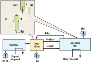
HHC removal and NGL recovery. Removal of HHCs (C6+ and aromatics) from the gas to be liquefied is necessary to avoid waxing and plugging in the main cryogenic heat exchanger (MCHE). The usual solution is to use a scrub column ahead of the liquefaction unit operating at liquefaction pressure and thermally integrated with the MCHE (Fig. 2).
 |
|
Fig. 2. Integrated LNG unit, scrub column.6 |
Although this method has been widely used, it has limitations in terms of inlet feed gas operating pressure and composition. In fact, a significant reduction in the scrub column pressure (to below the critical point) may be necessary, resulting in reduced liquefaction efficiency and increased power consumption.
In addition, when the gas becomes lean in C2 or C3+, it is difficult for the column to operate stably and efficiently due to insufficient liquid reflux in the column. An alternative to using a scrub column is to use an NGL extraction unit to recover the C2+ or C3+ hydrocarbons from the treated/dried gas. Conventional turboexpander technology can be used to produce a lean gas for liquefaction to comply with LNG product specifications.
Although propane and butane pose no freezing problem, they are removed together with the heavy hydrocarbons and can be separated and sold as liquid products. In addition, the extracted ethane is returned to the natural gas stream and used as refrigerant makeup or to supplement the fuel gas.
Although a front-end NGL extraction unit utilizing conventional turboexpander technology can handle a wide variety of feed gas compositions and effectively remove HHCs, it contains rotating equipment that impacts the capital investment and reliability of the FLNG facility. Today’s proprietary NGL recovery processes may reduce capital costs through the use of high-efficiency expanders/compressors and compact heat exchangers, but they may prove difficult and complex to operate. This complexity makes these processes less desirable for most FLNG facilities that prefer operational simplicity and minimum maintenance designs.
Note: In case the need exists for the removal of small quantities of HHCs from pipeline-quality gas to meet the more stringent specification for LNG, applying a silica-gel-based adsorption process to adsorb heavy hydrocarbons at high pressure (without removing lighter ones) is an economical option over other existing processes. In this case, the desorbed heavier components from the adsorption unit may be preferentially fed to the fuel gas system, which avoids the need for LPG removal and storage.
Nitrogen removal. The presence of more than approximately 1 mol% of nitrogen (N2) in LNG may lead to auto-stratification and rollover in storage tanks, presenting a significant safety concern. A higher percentage of N2 content in the feed gas also impacts the liquefaction process itself by reducing liquefaction
efficiency (additional refrigeration requirements per unit of LNG produced, due to the need to condense N2 in the feed gas).
In addition, high-N2-content feed gas may require treatment of (or the spiking of higher-Btu gas into) the BOG so that it may be used as the fuel gas for the gas turbine(s) on the FLNG facility. Therefore, the need exists for an efficient technique for the removal of N2 from LNG, even for relatively low N2 levels.
For feed gas containing N2 levels of approximately 1 mol% to 2 mol%, N2 can be removed in the end-flash section within an FLNG production facility. When N2 is present in high concentrations (greater than 5 mol%), it should be removed in the front section of the liquefaction unit to minimize liquefaction energy requirements. Several N2 rejection methods exist, including cryogenic separation, membranes and molecular sieve technology.
However, the only existing, viable, large-scale rejection technology is the use of cryogenic separation. In fact, the applications of membranes and molecular sieve technologies are generally limited to small scales. Membrane systems typically produce a waste N2 stream with fairly high hydrocarbon content (revenue loss), and the stream cannot be vented directly to the atmosphere. Therefore, waste N2 must be reinjected for sequestration or disposed of by other means. Molecular sieve technology is uneconomical when used to remove high levels of N2.5
Although economic justification exists to remove N2 from the feed gas before liquefaction, it is possible to remove N2 within the liquefaction process. When N2 removal is performed in the liquefaction section, it avoids the N2 rejection unit (NRU) product compression system, with refrigeration provided by a liquefaction unit refrigeration system. It also avoids losses associated with reheating and cooling feed gas for N2 rejection. However, in this scheme, a high level of heat integration with the liquefaction system adds to process complexity and operational risk, as neither the NRU nor the liquefaction system is conventional.7
When an NRU is to be installed in conjunction with the AGRU and NGL recovery units, the opportunity exists to integrate both facilities by eliminating repeat heat exchange equipment and recompression. For example, the selection of the NGL recovery unit outlet pressure can be set to match the best efficiency point of the NRU columns, and the rejected N2 from the NRU can be used to strip the AGRU solvent.
Such a simple integration concept can be incorporated into the design to achieve higher energy efficiency and reduce equipment counts while maintaining the operability of the overall process design.
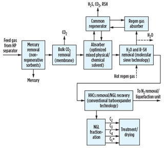
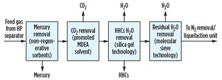
Integrated pretreatment scheme. Commercial process technologies, like those discussed above, can be integrated and configured into various FLNG pretreatment schemes, each offering unique benefits. Figs. 3 and 4 show typical pretreatment schemes for nearshore FLNG facilities based on two different types of supplied feed gas.
 |
|
Fig. 3. Typical integrated pretreatment scheme for nearshore |
 |
|
Fig. 4. Typical integrated pretreatment scheme for nearshore |
In the case of supplying pipeline-quality gas to the facility, a quick-cycle silica gel adsorption unit allows the single-step removal of both heavy hydrocarbons and water from natural gas; however, it does not generally achieve the water dewpoint of 0.1 ppm typically required in LNG production facilities.
Although trim layers of molecular sieves could be added to the bottom of this unit to obtain the required water specification, the large number of repeated cycles would impose a challenge for the molecular sieve by reducing its performance and lifetime. A more practical approach is to add a small molecular sieve dehydration unit downstream of the quick-cycle unit to remove the residual ppm levels of water from the gas.
In these integrated treating schemes, the main objective is to have an optimized, compact solution that can provide great process flexibility, safety and systems reliability while providing significant energy and capital cost savings. Note: The optimum solution will vary from project to project, as each feed gas is different.
Takeaway. A key step in the development of an attractive nearshore FLNG solution is the selection of an appropriate gas pretreatment system that best meets the project objectives. Several technology options can be integrated into the design of the gas pretreatment section in nearshore FLNG projects. When determining the optimal integrated pretreatment scheme, safety, weight, costs (CAPEX and OPEX), reliability and operational flexibility must be considered.
Next issue. Part 2 of this article will appear in the September/October issue of Gas Processing. GP
Acknowledgment
Thanks are due to Scott Northrop for reviewing this manuscript and providing useful comments.
Literature cited
1Festen, L., J. Leo and R. Vis, “CB&I Lummus and partners to turn LNG FPSO concept into a reality,” LNG Journal, September 2009.
2Purcell, T., “Maintaining FLNG operations in rough seas,” presented at the FLNG Forum, Perth, Australia, December 3–4, 2013.
3Mokhatab, S. and P. Hawes, “Optimal mercaptans removal solution in gas processing plants,” presented at the GPA Europe Spring Conference, Hamburg, Germany, April 22–24, 2015.
4Terrigeol, A., “Gas pretreatment on molecular sieves: Floating LNG specificities,” presented at the GPA Europe Spring Conference, Paris, France, March 13–15, 2013.
5Mokhatab, S., W. A. Poe and J. Y. Mak, Handbook of Natural Gas Transmission and Processing, 3rd Ed., Gulf Professional Publishing, Burlington, Massachusetts, 2015.
6Hagyard, P., H. Paradowski, D. Gadelle, P. Morin and J. C. Garcel, “Simultaneous production of LNG and NGL,” presented at the 14th International Conference & Exhibition on Liquefied Natural Gas (LNG 14), Doha, Qatar, March 21–24, 2004.
7Mokhatab, S., J. Y. Mak, J. Y. Valappil and D. A. Wood, Handbook of Liquefied Natural Gas, Gulf Professional Publishing, Burlington, Massachusetts, 2014.
 |
Saeid Mokhatab is an internationally recognized gas processing consultant who has been actively involved in several large-scale gas field development projects, concentrating on design, precommissioning and startup of processing plants. He has presented many invited talks on gas processing technologies worldwide and has authored or co-authored nearly 250 technical publications, including two Elsevier handbooks referenced by practitioners in the field. He has held technical advisory positions for leading professional journals, societies and conferences in the field of gas processing, and has received a number of international awards and medals in recognition of his outstanding work in the natural gas industry.


Comments