
Design for ultra-high-pressure H2S removal from natural gas
P. Roberts, formerly with Advisian, WorleyParsons, Twickenham, UK
What are the pressure design limits for natural gas H2S removal and associated dehydration facilities? This question was asked in the search for facility designs to remove H2S from sour gas at a pressure of 160 bara. The inlet gas to the facility is at 160 bara, and it requires export with minimum pressure loss for reinjection.
The existing facilities consist of mixed metal oxide beds to remove low levels of H2S and non-regenerable molecular sieve beds to remove the water formed in the reaction to remove H2S. The level of H2S increased over time, and was close to exceeding the capacity of the beds.
The decision was made to install an acid gas removal unit (AGRU) and an associated dehydration system to address the increased levels of H2S in the feed. Two main design options were presented:
- High-pressure (HP) design: Pressure letdown to 80 bara AGRU and 80 bara triethylene glycol (TEG)/molecular sieve dehydration plus compression (standard technology)
- Ultra-high-pressure (UHP) design: 160 bara AGRU and 160 bara TEG/molecular sieve dehydration.
A substantial financial incentive was identified to avoid the requirement of recompression and operate at UHP design. Here, the work carried out to validate the design of the UHP facilities is examined. It also discusses the work undertaken to verify the design and operation of an AGRU and an associated dehydration unit at UHP, as well as the challenges—both expected and unexpected—that were encountered.
At the start of the design, it was anticipated that the main difficulty in designing the UHP system would be the AGRU, due to the large increase in pressure from any previous design for natural gas. Therefore, it came as a surprise that the project could not move forward—not from a lack of confidence for an AGRU to operate at UHP, but due to difficulties in finding a suitable means of dehydration at this pressure.
Amine unit background. Amine units have been used for years to treat natural gas as the primary method of acid gas removal, although very few plants operate at pressures above
80 bara. Two examples exist, both in the North Sea:
- 100 bara: Statoil’s Sleipner platform
- 112 bara: Gaz de France’s K-12B platform.
Many refining applications exist up to 200 bara, but these process hydrogen-rich gas rather than natural gas.
Potential challenges of designing and operating an amine unit in hydrocarbon service at UHP were identified, as shown in Table 1.
The challenges that require more mitigation are Points 3, 4 and 5. Points 3 and 4 concern hydrocarbon absorption into amine at HP, and Point 5 concerns mechanical considerations. Therefore, it was decided to obtain further data from the following sources:
- A UHP amine literature survey
- Additional laboratory testing to meet areas not covered by published data
- Refinery data that may to be used to assess mechanical and operational issues.
UHP amine literature survey. Literature is available for the absorption of UHP natural gas and CO2 in amine; however, there is little information for H2S. Two main sources of data exist:
- The University of Alberta Gas Liquids Engineering Ltd. has published data in conjunction with the university at pressures up to 140 bara1
- Statoil, in conjunction with the University of Trondheim, has published data for pressures up to 200 bara.2,3
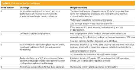
University of Alberta. One article1 tabulates the solubilities of methane, ethane and propane in 35 wt% MDEA for pressures up to 130 bara. Fig. 1 was developed from the data in the article.
 |
|
Fig. 1. Solubility of C1–C3 in aqueous solutions of MDEA.1 |
The required partial pressure of methane (for the facility at 160 bara) is 148 bara, which is only slightly in excess of the experimental data. Several conclusions can be drawn:
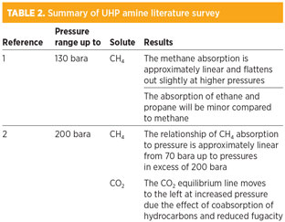
- Methane absorption is approximately linear and, in fact, flattens out slightly at higher pressures
- The absorption of ethane and propane is minor compared to methane at typical natural gas concentrations.
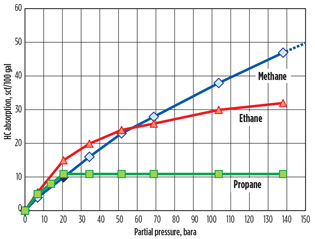
Statoil research center’s laboratory in Trondheim. The chart in Fig. 22 shows that the relationship of methane absorption to pressure is approximately linear from 70 bara, with some flattening out as the pressure approaches 200 bara. This confirms the data in the previous paper from the University of Alberta (Fig. 1).
 |
|
Fig. 2. Solubility of methane in MDEA.2 |
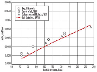
The chart in Fig. 33 shows how the equilibrium of CO2 in amine is affected by high partial pressure and consequent high absorption of methane. The CO2 equilibrium is shifted to the left (i.e., reducing the CO2 loading in MDEA) for high pressures of methane at the same partial pressure of CO2. The methane effectively displaces the CO2 in solution. This research was used to stabilize operation on the Sleipner CO2 removal unit. The reduced loading capability at HP was overcome by increasing the amine circulation and the reboiler duty.4
 |
|
Fig. 3. Effect of hydrocarbon absorption on CO2 equilibrium |
The results are relevant to the facility, as H2S loading may also be affected by the high partial pressure of hydrocarbons. The literature survey described above is summarized in Table 2.
Experimental results. In addition to the published data, one companya has provided its own experimental data, summarized in Table 3.
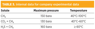
For the facility design case, the following addition data was commissioned from new experimental measurements:
- Confirmation and extension of data of CH4 + CO2 + MDEA (pressure 120 bara–200 bara)
- Extension of solubility data for CH4 + H2S + MDEA for lower temperatures and extension of pressure range (30°C, pressure 120 bara–200 bara).
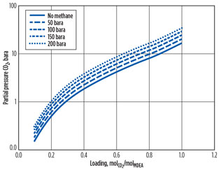
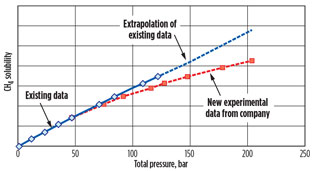
The new experimental results are shown in Fig. 4.
 |
|
Fig. 4. CH4 absorption data against pressure for |
The existing experimental data, up to 120 bara, shows the absorbed methane increasing in an approximately linear manner with increasing pressure. The new experimental data showed that the rate of increase declines with increasing pressure at UHP. This result reflects the trend shown in Figs. 1 and 2 for methane absorption at UHP.
A similar equilibrium shift was observed with H2S as CO2, as seen in Fig. 3.3 Two main conclusions from the literature survey and the experimental results were drawn:
- Acid gas loading in the amine will be lower than expected due to the high absorption of methane. The equilibrium shift reduces the acid gas loading in MDEA. This reduction will be offset by the higher partial pressure of acid gases at UHP. A simple mitigation option exists in increasing the circulation rate by approximately 10%.
- Increased hydrocarbon adsorption will result in a higher flash gas flowrate, which can be accommodated in design.
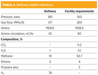
Reference plants. As previously stated, the highest known operating pressure of an AGRU treating natural gas is 112 bara; however, it is common for AGRUs to operate at higher pressures in refineries.
The example refinery absorber, situated in the residue hydrotreating unit (RHU), cannot be used for assessing hydrocarbon absorption since the hydrocarbon content is low. However, it is a good reference for safety/operational issues in a UHP absorber.
The biggest safety question for any HP amine unit is the HP/low pressure (LP) interface, which becomes a larger problem at UHP. The blow-by case can usually be designed with adequate low-level protection in the absorber and flash drum relief for gas breakthrough. Table 4 summarizes the UHP refinery reference and the facility requirements.
A site visit was made to the refinery to gather more information about the design and operation of the amine unit.
- The RHU was commissioned in the 1980s. Apart from refinery shutdowns, it has operated without interruption since that time.
- The RHU contains an amine unit in a reactor recycle loop.
- The amine unit was originally designed with MEA but switched to MDEA (40 wt%) and MEA (5 wt%).
- The amine unit has had high availability and operates without the problems commonly associated with amine plants, such as foaming and column flooding.
- The main findings from discussions with personnel at the site were mechanical and operational.
Mechanical. Notes on the mechanical condition of the amine unit included:
- The mechanical integrity of the amine absorber column after 30 years of operation is very good. The inspection report illustrates no major repair work to the vessel shell or head, only minor corrosion and pitting. The bottom of the vessel is lined with stainless steel and in good condition.
- The high head amine booster centrifugal barrel pumps (nine stages) are original to the facility and require a major overhaul only once every 10 years. They have proven extremely reliable.
- The existing high-differential-pressure-rich amine letdown valves are a Masoneilan-Lincoln-Log type (designed for HP liquid letdown/cavitation service). These valves operate for 12–18 months between overhauls.
Operation. Notes on the operational condition of the amine unit included:
- Historic measurements gave an H2S concentration of around 10 ppmv in the treated gas.
- The absorber has a chimney tray with a large disengagement space, but no mesh pad to prevent carryover of amine. However, little in the way of amine carryover is observed downstream.
- No foaming is observed.
Amine conclusions. A firm basis exists in both the experimental and operational data to proceed with the UHP amine unit design. The published data, supplemented by further experimental work by one company,a covered the range of operation required. With this data, the UHP AGRU can be designed with allowances for increased circulation rate and flash gas flow.
The observations at the refinery showed that the same basic design principles apply to UHP as at HP. At UHP, those problems outside of the normal operating envelope—for instance, in pump design—can be overcome.
Dehydration. Since amines are in aqueous solution, the sweetened gas leaving the amine column is water saturated and, therefore, must be dehydrated. The process technology options considered were molecular sieve and TEG dehydration. Molecular sieves have been used for adsorption at UHP; however, no references combine online regeneration. Reference plants exist for TEG up to 160 bara.
Molecular sieve. A choice of designs exists for molecular sieves:
- Combine gas dehydration with natural gas sweetening, provided that the H2S loading is not too high.
- Locate the sieve downstream of the amine AGRU for dehydration.
The required inlet H2S concentration (0.1 mol%) is well within the limit for gas sweetening; therefore, molecular sieves could be used for combined dehydration and acid gas removal. This would eliminate the need for the upstream AGR; however, acid gas removal would be required from the molecular sieve regeneration gas, which may be at UHP or HP.
COS formation during the adsorption cycle effectively blocked the use of molecular sieve H2S removal technology, which directly impacted the total sulfur specification of the product gas. COS formation is not an issue particularly related to UHP, but the quantity is a concern for meeting the tight total sulfur product gas specification.
For the design case with 1,000-ppmv H2S in feedgas up to 80 ppmv, COS would be formed even for low-COS molecular sieves, which would exceed the treated gas total sulfur specification. Although removing this COS from treated gas is technically possible with mixed metal oxide beds, it is in practice not feasible as it would require a high bed changeover frequency. Therefore, it was decided to investigate the use of molecular sieves for dehydration only. Table 5 summarizes the references for HP molecular sieve units with regeneration.
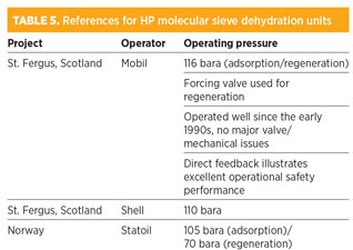
Gas dehydration by molecular sieve is well established for pressures up to 70 bara, and some units are operating in the dense phase (> 100 bara). However, no experience exists of operating these units at 160 bara with regeneration. The main concerns of operating at UHP are:
- Increased coadsorption of hydrocarbons, leading to a longer mass-transfer zone and the increased possibility of coke formation on the bed (faster degradation and reduced bed life)
- HP regeneration is inefficient
- LP regeneration increases the regeneration time and requires compression
- Increased vessel wall thickness means a longer heating/cooling cycle.
The following mitigations have been recommended by vendors for adsorption:
- Longer bed depth (to counter longer mass-transfer zone)
- More bed volume (to counter increased degradation and reduced bed life)
- High-strength material and multiple vessels of smaller capacity (to reduce wall thickness).
Regeneration at a pressure lower than 100 bara has two advantages:
- Application of a well-established process for subsequent treatment of regeneration gas
- Approximately 30% reduction in regeneration gas flowrate.
However, the disadvantages are:
- Increased cycle time (maximum depression rate 2 bar/min–3 bar/min)
- Requirement of a recompression facility.
During the course of the investigation, it was identified that molecular sieves with trace amounts of H2S in the feed can cause spikes of H2S on regeneration. To minimize the adsorption of H2S, a 3A molecular sieve instead of a 4A sieve should be selected. The pores of the 3A molecular sieve are too small for the H2S molecule to enter; however, a small amount of H2S is still likely to be adsorbed on the surface of the molecular sieve (the total weight adsorbed on the bed will be on the order of 100 g). This small quantity of H2S is sufficient to increase the concentration of H2S to approximately 100 ppmv in a “spike.” This spike will blend with the feed gas to put off the specification of the treated gas.
To mitigate this problem, it will be necessary to install beds of mixed metal oxides to remove the H2S spike from the regeneration gas. The mixed metal oxide beds should be sized to be changed out every three years in conjunction with the molecular sieve. Only one supplier was able to estimate H2S levels on which to base the design; therefore, it was not possible to confirm this value from experience or from other suppliers. This means that the beds could be undersized, which would result in additional changeouts.
TEG dehydration. Dehydration of TEG is a proven method of dehydration at UHP conditions. As the process requires only a single UHP vessel, it is consequently less expensive than the molecular sieve process. In addition, the gas specification (33 ppmv water) is achievable by TEG dehydration with gas stripping. Table 6 summarizes the TEG UHP references.
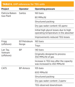
As high TEG losses were observed on the Patricia Baleen, Lay Tay and CATS projects referenced in Table 6, it was decided to investigate the solubility of TEG in natural gas at UHP by finding experimental data and validating a proprietary simulation program using Peng-Robinson thermodynamic package against the experimental results.
Little published data for TEG solubility in hydrocarbons exists.5 This data goes up to only 90 bara, although it shows the “bowl shape,” with solubility increasing at higher pressures. The referenced article5 explains how this is due to a retrograde phenomenon that occurs when the gas approaches the cricondenbar.
Depending on the extrapolation of the experimental data, a threefold to fivefold increase in TEG solubility will be seen from 50 bara to 160 bara. TEG losses (due to solubility in gas only) at 160 bara and 25°C, at a gas rate of 260 MMscfd, will be in the range of 40 kg/d–50 kg/d. This TEG loss will increase the operating expense of the unit and operator intervention.
Retrograde condensation of liquid TEG in the export pipeline would also result from the reduction in solubility of TEG with pressure. Literature warns: “TEG will accumulate as a liquid slug, causing significant plugging of the flow cross-sectional area.”5
Dehydration conclusions. Molecular sieve dehydration is unproven at UHP in regeneration service. The H2S spike uncovered during the analysis, although not connected with UHP operation, sparks concern over the ability to design an appropriate molecular sieve system for this application.
TEG dehydration technology, with experience at operating at UHP, should be better suited to this application. However, concern exists at the high level of TEG loss at UHP. This poses an operational problem in providing makeup to a small inventory system. It also raises the concern that this would lead to TEG condensation in the export gas pipeline as the pressure is reduced (i.e., retrograde condensation). GP
Note
aBASF’s OASE Gas Treating Excellence amine treating technology was used in the generation of the experimental results.
Acknowledgment
This paper was prepared with support from Dr. Ralf Notz, senior technology manager of OASE Gas Treating Excellence at BASF SE, whom the author also wishes to thank.
Literature cited
1Carroll, J. J., F. Y. Jou, A. E. Mather and F. D. Otto, “Solubility of methane and ethane in aqueous solutions of MDEA,” Journal of Chemical and Engineering Data, University of Alberta, Canada, July 1998.
2Jan Addicks, J. and G. A. Owren, “Solubility of carbon dioxide and methane in aqueous MDEA solutions,” Journal of Chemical and Engineering Data, Norwegian University of Science and Technology, Trondheim, Norway, May 2002.
3De Koeijer, G. and E. Solbraa, “High pressure gas sweetening with amines for reducing CO2 emissions,” Proceedings (Elsevier) from IEA GHGT-7 Vancouver 2004, Statoil ASA, Research and Technology, Trondheim, Norway.
4Buller, A. T., O. Kårstad and G. de Koeijer, “Carbon dioxide—capture, storage and utilization, Statoil research and technology memoir No. 5,” Stavanger, Norway, 2004.
5Jerinić, D. et al., “The measurement of the triethylene glycol solubility in supercritical methane at pressures up to 9MPa,” Elsevier B.V., March 2008.
6Aspen Technology, Aspen HYSYS v7.3 online manual.
 |
Paul Roberts was formerly principal process consultant within Advisian, the independent consulting business line of WorleyParsons. He is now an independent consultant. Mr. Roberts graduated with a BSc degree in chemical engineering from Birmingham University and is a chartered engineer.


Comments